

 EU
EU
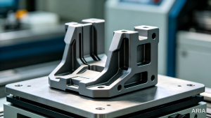
Machining flat surfaces is simple. The tool moves along one plane, the cutter engages the material at ninety degrees, and the result is a straight surface. Most parts need more than that. A bracket needs a chamfer so it does not cut a hand on assembly. A pressure vessel needs a bevel so a weld can penetrate properly. A slide needs a dovetail so two parts can move against each other without play. None of these features sit at ninety degrees to the machine axis, and none of them come from a standard milling pass.
Each one needs a set of angle cuts that cnc machining handles far more consistently than a manual tool ever could. Angle milling is the process that produces them. It covers a wide range of precision machining work, from a small edge chamfer cut on a basic three-axis mill to a compound bevel machined on a five-axis centre. The tooling, the setup, and the level of accuracy needed all change depending on the feature, but the underlying goal stays the same: removing material at an angle other than ninety degrees to create a functional or cosmetic surface.
It is a milling operation that shows up on nearly every machined part sooner or later. This guide walks through how angle milling works, the tools and machines involved, the materials it suits, and where it fits against other cnc machining operations. It also covers the practical side: what typically goes wrong, what it costs, and how to judge whether a supplier can actually deliver it to the tolerance a drawing calls for.
What Is Angle Milling?
Angle milling is a CNC machining operation that removes material at an angle other than ninety degrees to the primary plane, producing a sloped or angled face, edge, or pocket wall instead of a flat one. It comes from tilting the cutter, tilting the workpiece, using a cutter with the angle built into its geometry, or coordinating several axes at once. The result is angle cuts, not flat surfaces, made on purpose.
Angle milling and angular milling are usually treated as interchangeable on the shop floor. Where a line is drawn, angle milling means a single fixed angle from a dedicated tool, while angular milling covers broader, multi-surface angled work. Either term points to the same angle milling process, so a drawing using one should be read the same as the other.
Right angles do not cover every design need. A chamfer removes a sharp edge, a bevel opens a joint for weld penetration, and a dovetail slot locks two parts together without play. Aerospace structures use angled faces to shed weight without losing strength. That is why angle milling, done with the right angle cutters, sits alongside facing, slotting, and profiling as a core cnc machining operation.
How Is Angle Milling Achieved? (Key Methods)
There is more than one way to produce an angled surface, and the right choice depends on the feature size, the required accuracy, and what the machine and specialized fixtures allow when setting the milling angles a drawing calls for.
Tilting the Workpiece with Angle Blocks
The part can be clamped at an angle rather than flat on the table. Angle blocks, a sine plate, or a rotary fixture hold the workpiece so the angled face becomes horizontal relative to the spindle. A standard end mill then cuts what looks like a flat face from the tool’s point of view, but on the finished part it sits at the programmed workpiece angle. This method works well for larger angled faces where a purpose-made angular cutter would be expensive or hard to source, and it does not require a machine with a tilting head. It does, however, need the specialized fixtures to be rigid enough to resist the lateral forces an angled cut generates.
Tilting the Cutter Using Angle Heads
Some machines, or attachments fitted to them, allow the spindle itself to tilt. Angle heads, sometimes described as a mill head attachment, mount onto the machine and swivel the cutting tool to the required tool angle without moving the workpiece. This is useful when a part has several angled features at different orientations, because the workpiece stays clamped in one position while the mill head does the adjusting. Alignment matters here: even a small error in how the head is set produces an angular error on every feature it cuts.
Using Purpose-Made Angle Cutters
Where the machine cannot tilt and the workpiece cannot easily be angled, a specialist angle cutter does the job on its own. Single angle cutters and double angle cutters, the two most common angle milling cutters, carry the required angle in their own geometry, so a standard three-axis setup produces the angled feature without any special fixturing. Most of these tools are ground to standard angles such as 30°, 45°, or 60°, which is the fastest and most accessible route for common chamfers and bevels, and it is the method most CNC shops default to for edge preparation.
Multi-Axis CNC Coordination
On multi-axis cnc machines, the spindle and the table can move together, tilting and rotating in coordination as the cut proceeds. This produces compound angles and other angled surfaces that slope in two directions at once, which neither a tilted workpiece nor a fixed-angle cutter can achieve alone. It is the method behind swept bevels and angled pockets on aerospace and automotive parts, and these angle milling operations depend heavily on accurate rotary axis calibration to hold the programmed angle.
How Does Angle Milling Differ From Conventional CNC Machining?
Cutting Angle and Tool Engagement
Conventional milling, sometimes called plain milling, moves the cutter perpendicular or parallel to the workpiece surface, producing flat surfaces, straight slots, and square profiles. Angle milling changes the relationship between the cutting tool and the workpiece surface, so the cutting edge engages the material at a non-standard angle throughout these angle cuts. That changes the chip load along the edge and usually calls for a lower feed rate than an equivalent flat cut would use.
Surface Geometry Produced
A conventional pass leaves a surface aligned to the machine’s own axes. Angle milling deliberately breaks that alignment to leave sloped, chamfered, or bevelled angled surfaces at the desired angle. The geometry produced is the entire point of the operation, not a byproduct of tool wear or setup error, which is why the tolerance on the angle itself is usually specified separately from the linear dimensions.
When Each Method Applies
Conventional milling remains the right choice for facing, slotting, and general profiling, anywhere a flat or square feature meets the design intent. Angle milling takes over the moment a drawing calls for a chamfer, a weld-prep bevel, a dovetail, or any surface that is not at the correct angle relative to the reference plane. Most parts use both operations in the same milling operation, one for the bulk shape and the other for the angled details.
The Angle Milling Process
Every angle milling job follows the same underlying machining process, even though the details change with the feature being cut.
Workpiece Setup and Fixturing
Accuracy starts before the spindle turns. The workpiece setup needs a clear, verified relationship between the drawing datum, the fixture, and the machine coordinate system. If the angled feature is referenced from a primary reference surface, that surface has to sit against the fixture datum and be checked before cutting starts, since the lateral forces generated during an angled cut will expose any looseness in the clamp. Confirming the workpiece angle before the first cut catches most errors before they turn into scrap. A small setup error at this stage produces a much larger angular deviation across a long bevel than it would on a short one, because the error compounds with distance, and it is exactly the kind of error that puts tight tolerances out of reach.
Tool and Parameter Selection
The cutting tool is chosen to match the feature: a single-angle cutter for a simple chamfer, a double-angle cutter for a symmetrical groove, or a tilted end mill where the angle changes along the surface. Spindle speed and feed rate follow the same material rules as any milling operation, but angled cutters complicate the cutting parameters because the effective cutting diameter changes with depth of cut. Running the tool at a speed set for its widest point overworks it near the tip, where the diameter and the surface speed are both smaller.
Cutting the Angle
For a simple chamfer cut with a chamfer mill, the toolpath is straightforward: position at the edge, set the depth of cut that produces the required chamfer width, and feed along the edge. For a larger bevel, multiple passes usually cover the full face width, and the stepover between them sets the surface finish quality. For multi-axis work, the CAM system holds the tool at a constant angle relative to the surface normal as it moves, which keeps this part of the angle milling process steady even as the surface orientation changes.
Inspection and Verification
Angled features are harder to check than flat ones because the acceptance criteria usually cover both the angle and its location. A simple chamfer might only need a visual check or a chamfer gauge. A structural bevel calls for angle gauges or optical comparators. A compound angle held to tight tolerances usually needs coordinate measuring machines, because these measuring machines are the only practical way to confirm both the surface location and its normal direction against the nominal geometry and hold precise angles across a batch.
Types of Angle Milling Cutters
The cutter chosen sets the milling angles achievable without repositioning the workpiece, and matching cutter to feature keeps angular surfaces consistent across a batch of angular milling work. Selecting from the right angle milling cutters up front avoids unnecessary tool changes.
Single-Angle Milling Cutters
A single angle cutter has cutting teeth around a conical face set at one fixed angle, commonly 30°, 45°, or 60°. Many single angle cutters used purely for edge preparation are simply marketed as a chamfer mill ground to one angle. It produces one angled surface per pass and suits chamfering, edge beveling, and simple angled slotting at a specific angle. Because it only cuts on one side, it gives good control over which direction the slope runs, which is why single angle cutters remain the default choice for a straightforward chamfer.
Double-Angle Milling Cutters
Double angle cutters, sometimes called double angle milling cutters, carry teeth on both sides of the circumference, cutting two angled surfaces at once without a tool change. This suits V-grooves, dovetail slots, angled slots, and undercuts, and it comes in both symmetrical and asymmetrical forms depending on whether the two angular slots need to match.
Specialised Angled Tools: Chamfer Mills, Dovetail and Countersink Cutters
Chamfer mills are the most common angled tool on a CNC floor, usually built with a 60°, 90°, or 120° included angle to cover the standard range of edge chamfers. Dovetail cutters produce the fixed-angle slots used in sliding mechanical joints, while t slot cutters cut the perpendicular slots used to anchor fixtures and workholding. Countersink tools bevel the edges of a drilled hole, most often to seat a fastener flush with the surface. Each of these is a fixed-geometry cutting tool, and coated cutters are worth the extra cost on harder materials, trading flexibility for speed and repeatability on high-volume work.
Machine Requirements for Angle Milling
Spindle and Head Configuration
The single biggest factor is whether the spindle itself can tilt. A milling machine with a universal or adjustable mill head can set most standard chamfer and bevel angles without extra fixturing. Selecting the right mill head configuration up front avoids costly rework later in the job. Without that feature, the milling machine still handles angle milling perfectly well using fixed-angle cutters or a tilted workpiece, but the range of angles achievable in one setup is more limited.
Fixturing and Rotary Table Capability
A rotary table, a sine plate, angle plates, or a set of angle blocks lets a standard three-axis machine reach angles its spindle cannot, correcting the workpiece angle without a tilting head. Machine rigidity matters more here than on flat work, because angled cuts generate lateral forces that a loose fixture will not absorb. On four and five-axis equipment, the calibration of the rotary axis becomes part of the accuracy chain, and thermal drift over a long run can shift even tight tolerances more than the toolpath itself does.
What to Check Before Quoting a Supplier
An engineer sourcing angle milling work is really asking a narrower question: can this shop hold the angle on this specific feature. Three things are worth confirming before sending a drawing out.
Angular Tolerance. Ask what angular tolerance the milling machine routinely holds on a standard three-axis setup versus a calibrated five-axis one, since the difference is often ±0.3° against ±0.05°.
Inspection Method. Ask how they inspect angled features, because a shop with no coordinate measuring machines on the floor will struggle to verify a compound angle regardless of how well it machined it.
Cutter or Tilted Axis. Ask whether the quoted setup uses a fixed-angle cutter or a tilted axis, since that decision affects both lead time and repeatability across a batch.
Aria’s machining team works through these questions on every angle milling enquiry before quoting, as part of standard precision machining practice, because the answer changes the tooling and the price.
Materials Suitable for Angle Milling
Aluminium and Lightweight Alloys
Aluminium is the most forgiving material for angle milling. It cuts cleanly at high speed, allows fast material removal, produces minimal burring at chamfered edges, and tolerates the uneven chip thickness that angled cutting geometry produces. 6061 is a common choice for structural angle milling work, and with sharp carbide tooling and a spindle speed matched to the cutter diameter, cutting speeds in the 300 to 500 metres per minute range are typical, depending on machine rigidity and coolant strategy.
Steel and Stainless Steel
Stainless steel needs more care than aluminium because its material hardness increases quickly under the cutting zone. The uneven chip thickness in angled cutting creates spots where the tool partly rubs rather than cuts cleanly, which accelerates that hardening. A sharp, coated carbide tool run at a steady 80 to 120 metres per minute with flood coolant gives consistent results. Titanium alloys behave similarly but generate more heat at the cutting edge, so a lower speed with stronger coolant flow protects the tool and holds the angle across a run. Letting the tool dwell at the entry point before it starts feeding is worth avoiding on either material, since that rubbing action raises material hardness at the surface before the cut has even begun.
Plastics and Composites
Engineering plastics such as POM and nylon machine cleanly at low speed with sharp tooling and usually need no coolant at all. Acrylic chips well but cracks if the tool is dull or the feed too slow, because the heat generated melts the material instead of cutting it. Carbon fibre composite is a separate case, and one that suits complex geometries well: the fibre is abrasive enough to wear standard carbide quickly during material removal, so diamond-coated or PCD tooling extends tool life, and a compression-cutting geometry reduces the fibre delamination that a standard chamfer mill can leave at the exit edge.
Angle Milling vs Other CNC Machining Operations
Angle milling sits alongside plain milling, face milling, profile milling, and slot milling as one of the standard CNC operations, though only angle milling is built specifically around producing a controlled non-perpendicular surface.
Angle Milling vs Face Milling
Face milling produces a flat, horizontal surface with a face mill moving at a fixed height, and material removal rates with a face mill are usually far higher than any angled operation could match. It is fast and has no angular component at all. Angle milling exists specifically to produce the surfaces a face mill cannot, and the two are almost always used together on the same part, one for the bulk flat surfaces and the other for the angled details around them.
Angle Milling vs Profile Milling
Profile milling follows a contoured edge or shape using an end mill, typically to produce the outer boundary of a part or other complex geometries. It can include some angular work if the profile itself is sloped, but it is not built around angular accuracy the way angle milling is. Where a profile needs a tight angular tolerance rather than just a contoured shape, angle milling is the more direct route.
Choosing by Cost and Setup Time
The table below compares the four operations across the factors that usually drive a sourcing decision.
| Factor | Angle Milling | Face Milling | Profile Milling | Slot Milling |
| Typical setup time | Low for standard angles, higher for compound angles | Low | Moderate | Low |
| Typical angular tolerance | ±0.1° to ±0.5° | Not applicable | ±0.05 to ±0.1 mm | Not applicable |
| Relative cost driver | Tooling choice and inspection method | Cycle time | Toolpath length | Cycle time |
| Best fit | Chamfers, bevels, angled pockets | Large flat surfaces | Contoured boundaries | Slots, keyways |
At Aria, a straightforward chamfer using a fixed-angle cutter adds only seconds to a cycle and rarely changes the quote. A compound bevel that needs a calibrated five-axis setup and coordinate measuring machines for verification is a different cost picture, mainly because of the inspection time rather than the cutting time itself. Engineers who need a quick estimate at the design stage should treat angular tolerance and the surface finish called for, not the angle itself, as the main drivers behind the cutting parameters and the price.
Applications and Industries of Angle Milling
Chamfers, Bevels and Other Angled Features
The most common use of angle milling is preparing an edge: removing sharp edges, opening a joint for a weld with beveled edges, or creating a lead-in that guides a mating part into position during assembly. The result is angled surfaces that assemble cleanly without secondary fitting. These features are so routine on machined parts that they often go unmentioned on a drawing beyond a simple chamfer callout, but they still rely on the same angle milling principles as a more complex feature.
Slots, Grooves and Dovetails
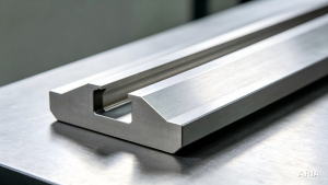
Dovetail slots and T-slots use angled walls to create a mechanical lock between two parts, most often in machine tool ways, slides, and fixtures that need to move accurately without play. Mould and die work uses the same angled principles for draft angles, which let a moulded part release cleanly from its cavity. These features are almost always cut with a dedicated form tool matched to the required angle, since machining them with a standard end mill would take far longer and produce a less consistent result.
Aerospace and Automotive Components
Aerospace components use angled faces to reduce weight and manage stress distribution, often on structural brackets and turbine blades where every gram matters. Automotive components use similar principles on smaller features, tapered slots, angled mounting faces, and edge chamfers on body and engine parts, where cosmetic finish matters as much as function.
Advantages and Limitations of Angle Milling
Advantages of Angle Milling
Dedicated angular tooling produces consistent results across a production run, since the geometry comes from the cutting tool rather than from a programmed toolpath that could drift. A chamfer cut with a sharp tool at a set depth holds the same surface finish and the same precision on part one and part five hundred. This consistency matters most on aerospace components and any part where beveled edges must repeat exactly from batch to batch. The process also reduces the need for secondary operations: a bevel or chamfer machined in the same setup avoids a separate grinding or deburring step, which saves both time and handling risk.
Limitations of Angle Milling
Setup complexity rises with angular accuracy. A rough chamfer for deburring needs almost no verification, but a feature held to tight tolerances needs first-part inspection and periodic rechecking through a production run. Tool wear is also faster than on flat work, because the tip of an angled cutter runs at the smallest effective diameter and the lowest surface speed, which means it wears first and changes the finished angle slightly as it does.
Best Practices for Angle Milling
Selecting and Setting Up Angle Cutters
Match the cutter to the feature rather than defaulting to whatever is already in the tool crib. Single angle cutters suit a simple chamfer; double angle cutters suit a symmetrical groove in one pass. Coated cutters are worth the extra cost on stainless steel or titanium alloys, where material hardness wears a standard high-speed steel cutter too quickly to hold a consistent angle across a batch.
Coolant and Cutting Parameters
Flood coolant suits steel and titanium, where heat dissipation matters more than chip clearing. Mist coolant, or none at all, usually suits aluminium and plastics, where the priority is preventing chip welding rather than managing heat. Balancing spindle speed against feed rate protects the cutting edge as much as the coolant strategy does. Cutting parameters are worth testing on a scrap piece before committing to a full run, since the varied chip thickness in angled cutting behaves differently to a straight peripheral cut even at the same nominal feed rate.
Quality Verification
Build the inspection method into the process plan rather than deciding it after the part is cut. A drawing that specifies tight tolerances but does not say how it will be measured leads to disagreement between machining and quality teams even when the part is genuinely within spec. First-part approval, followed by periodic in-process checks, catches drift from tool wear or thermal change before it affects a whole batch.
Common Challenges in Angle Milling
These angle milling operations are the ones most CNC shops run into repeatedly, and most trace back to one of the causes below.
Angular Error on Angular Surfaces. Usually traces back to setup misalignment or an uncalibrated rotary axis, leaving the feature short of the correct angle. The fix is verifying the setup with angle gauges and inspecting the first part before running the rest of the batch.
Chamfer Width Variation. Comes from inconsistent depth of cut or a tool wearing at the tip. Checking depth in-process and replacing tools at a defined interval keeps width consistent across a run.
Chatter on Angled Faces. Caused by long tool overhang, poor machine rigidity, or insufficient workholding against the lateral forces of an angled cut. Reducing overhang, splitting the cut into multiple passes, and adjusting feed, rather than simply slowing down, often resolves the marks left on angled surfaces.
Burr at Chamfer Exit. Usually a dull tool or the wrong feed direction at the exit point. Climb milling on the exit side and replacing dull tooling both reduce this reliably.
Cost of Angle Milling
Material and Complexity. Higher material hardness increases tool wear and cycle time, and complex geometries or compound angles at a specific angle add setup and programming time on top of the cutting itself.
Precision Requirements. A loose chamfer tolerance costs little beyond the cutting time. Tight tolerances add first-part inspection, coordinate measuring machine time, and sometimes a slower feed rate, all of which show up in the quote.
Tooling Choice. Standard chamfer mills are inexpensive and widely stocked. A custom angle, a large bevel cutter, or a dovetail cutter matched to a specific slot width costs more, and a job needing multiple cutters or specialized fixtures may extend lead time if any of them need to be sourced specially.
Safety Considerations for Angle Milling
PPE and Chip Ejection. Angled cutting throws chips less predictably than a flat pass, so a full face shield alongside safety glasses is worth the extra step, and gloves should stay well clear of the sharp edges on an unmounted cutter and the angled edges it produces.
Fixture and Guard Checks. Loose angle blocks or an unsecured rotary table under the lateral forces of a cutting load are a real hazard, not a theoretical one. Checking that every clamp on the specialized fixtures is tight before starting, and that machine guards are positioned to catch the wider chip scatter angled cuts produce, takes a minute and prevents most incidents.
Tool Maintenance and Tool Life
Wear Inspection for Angle Cutters. The tip of an angled cutter wears first because it runs at the smallest effective diameter. Checking it after every major run, or sooner if surface finish starts to degrade, catches wear before it affects a batch.
Sharpening and Replacement Cycle. Carbide chamfer mills, single angle cutters, and double angle milling cutters all need diamond grinding to resharpen, which costs more than resharpening a standard end mill but extends useful tool life significantly. Scheduling replacement by cutting hours or part count, rather than waiting for visible failure, keeps chamfer width and angle consistent across a production run.
Alternatives to Angle Milling
Angle Grinding. A manual, freehand process suited to rough shaping or finishing rather than precision work. It is faster for a one-off, loose-tolerance bevel but introduces more variation than milling.
Precision Grinding. Often used after angle milling to refine a critical surface to tight tolerances and a better surface finish than milling alone achieves, particularly on hardened parts.
Multi-Axis CNC Machining. Where a compound angle, complex geometries, or a large batch justifies the investment, a multi-axis cnc centre can cut the angled feature and the surrounding geometry in one setup, trading a higher machine cost for fewer fixture changes.
FAQs About Angle Milling
Q: What is the difference between angle milling and angular milling?
A: In practice, the two terms are used interchangeably across the machining industry as names for the same angle milling process. Where a distinction is drawn, angle milling usually refers to a single angle produced with a dedicated cutter, while angular milling covers multiple angles or broader multi-surface work. A drawing using either term should be read the same way unless it specifies otherwise.
Q: What tools are used for angle milling?
A: Single angle cutters and double angle milling cutters, the two most common angle milling cutters, handle most chamfers, bevels, and grooves. Chamfer mills, typically with a 60°, 90°, or 120° included angle, cover standard edge preparation for common angle cuts. Dovetail cutters, t slot cutters, and countersinks handle their specific fixed-angle features, and a standard end mill tilted on a multi-axis machine covers compound or variable angles that a fixed-geometry cutter cannot reach.
Q: How can you achieve accurate angle milling results?
A: Accuracy comes from controlling three things together: workpiece setup and datum alignment, tool condition, and the inspection method used to verify the result. A three-axis setup with careful fixturing and a sharp cutter typically holds ±0.3° to ±0.5°. A calibrated five-axis milling machine with coordinate measuring machines for verification can hold precise angles down to ±0.05° or better, which is where tight tolerances become realistic. The limiting factor is usually calibration and thermal stability rather than the machine’s stated positioning accuracy. These same principles apply across the full range of milling angles a shop might be asked to hold.
Q: Can angle milling be used on stainless steel or titanium?
A: Yes, though both materials need more careful parameter control than aluminium. Stainless steel raises material hardness quickly under the cut, so coated cutters run at a steady speed with flood coolant avoid the rubbing that accelerates hardening. Titanium alloys generate more heat at the cutting edge, so a lower speed with strong coolant flow protects tool life and holds the angle consistently across a run.
Q: Is angle milling better than angle grinding?
A: For precision work, yes. Angle milling on a CNC machine, often with a chamfer mill or a dedicated angle cutter, produces a repeatable angle and consistent surface finish across a batch, because the geometry is controlled by the tool and the program rather than by hand, holding the same precision from the first part to the last. Angle grinding remains useful for a quick, one-off bevel where tight tolerances are not the priority, but it introduces more variation than a milling operation would on the same feature.
