

 EU
EUCAD for CNC is the design stage where a part is built as a precise 2D or 3D model. Exact dimensions and tolerances get set inside CAD software, creating the blueprint that CNC machines follow. That first file matters because it sets the baseline for machining accuracy, material use, turnaround time, and overall production efficiency. This holds true whether the job is prototyping or mass production.
Getting from that file to a finished part runs through four types of software: CAD, CAM, control, and simulation. Each one hands off to the next. CAD comes first in that chain, and the CAD file shapes most of what follows. How cleanly a design translates into G-code decides a lot downstream. Rework, scrap, and delay all trace back to that translation step, long before a CNC machine reaches the spindle.
Understanding that first file is essential. This guide starts with the CAD file itself. From there it covers CNC workflow stages, common file formats, CAD software compatibility, and the major CAD/CAM options. It ends with how to choose the right setup for accurate, efficient machining.
What Are CAD Files?
CNC CAD, short for computer-aided design, is the design phase where a part exists only as data. Using CAD software, an engineer builds a precise 2D or 3D CAD model with defined dimensions and tolerances. That model takes shape inside a CAD program. The CAD design becomes the exact blueprint for producing the part on a CNC machine.
A CAD file is not a rough sketch of what a part might look like. It carries exact geometry instead. Every stage downstream, the CAM program, the tool paths, the CNC machine itself, treats that geometry as ground truth. An incorrect fillet radius or hole position inside a CAD model travels straight through to the finished part. That is one reason clean CAD design reduces material waste later on the shop floor.
How CNC CAD Fits into the Workflow
Machining begins long before any cutting tool touches stock. The path from idea to metal runs through three distinct stages. Each stage depends on the accuracy of the one before it.
Design (CAD)
A digital object is built with exact measurements, dimensions, and tolerances, using CAD software such as Fusion 360 or SolidWorks. Every wall thickness, hole diameter, and fillet radius gets locked into the CAD file here. That happens long before a cutting tool touches stock. Mistakes caught inside CAD software are cheap. Mistakes caught later, on an industrial machine running real material, are not.
Programming (CAM)
The CAD file moves into CAM software next, short for computer-aided manufacturing. This step sits inside the broader CNC software workflow. The CAM program translates the drawing into tool paths and G-code. Feed rate, spindle speed, cutting tool selection, and cut sequence all get decided inside the CAM software at this point.
Generating G-code and toolpath generation sit at the centre of this step. CAM software acts as the translation layer between a static CAD model and a CNC machine that only understands movement. Many CAM programs also include simulation features. Teams use those simulation features to run virtual checks on the machining process before cutting physical material.
Execution (CNC)
The CNC machine is built around computer numerical control. It relies on CNC control software to read the programmed instructions. Motors move the spindle or the table with precise control. G-code files guide those movements during machining operations, cutting, milling, or drilling the physical part from raw stock. Whatever happened during CAD design or CAM programming, mistakes finally show up here. On the CNC machine, that usually means scrap material or a wasted machine cycle.
Popular CNC CAD File Formats
Not every CAD file format suits every CNC machine or every job. CNC applications differ widely, from routers cutting sheet stock to five-axis mills holding tight tolerances. The right file type depends on which application is in use.
STEP (.step / .stp)
The standard exchange file format for solid 3D models, used across most CAD software and CAM programs alike. It preserves exact geometry rather than approximating it. That makes it the safest default file format when sending a design to a machine shop. Most CAD programs export STEP files without trouble, and most CAM software reads them cleanly. Machining centres tend to prefer STEP for both turning operations and precision machining on CNC milling machines.
IGES (.iges / .igs)
An older file format, still used for sharing surface geometry data. It predates STEP and can struggle with complex shapes and complex toolpaths built from solid features. Enough legacy CAD software still relies on IGES that most CAM programs keep support for it.
STL
A mesh based file format, built from triangulated surfaces rather than true geometry. STL files suit 3D printing and rapid prototyping well, where an approximation of the surface is good enough. For CNC machining, STL is a weaker choice. Tight tolerances and exact curves do not survive translation through a mesh very well.
DXF / DWG
2D drawing file formats, frequently used for flat bed CNC routers, laser cutters, and plasma cutters. DXF files tend to travel better between different CAD programs. DWG is AutoCAD’s native file type, and not every CAM program reads it directly. For simple 2D artwork destined for a laser cutter, some designers still export from vector tools such as Adobe Illustrator. Those tools suit artistic projects better than dimension-critical CNC work. CAD software remains the standard for anything that needs real dimensional control.
Parasolid based file formats such as X_T show up occasionally too. That happens mostly when both sides of a project already work inside SolidWorks or another Parasolid kernel CAD program. They carry precise geometry in a smaller file, though they see far less general use across CNC machines than STEP.
CAD Software and CNC Machine Compatibility
A quick look at how the popular CAD programs commonly used in CNC workflows line up against CNC machines, with common CAD export formats including STEP, IGES, and DXF and the table below highlighting their key features:
| CAD Software | CAM Integration | Typical Export Format | Learning Curve |
|---|---|---|---|
| Fusion 360 | Built-in CAM | STEP, G-code | Easy |
| SolidWorks | Via SolidCAM | STEP, IGES | Moderate to advanced |
| AutoCAD | Plug-ins required | DXF, DWG | Moderate |
| FreeCAD | Basic CAM included | STEP, IGES | Beginner friendly |
| Siemens NX | Full CAM suite | STEP, Parasolid | Advanced |
Machine compatibility also depends on the tolerance target. For high precision work, CNC machining in some applications can reach as tight as ±0.005mm.
The pattern holds across most CAD software. The tighter the CAD/CAM integration, the less time gets spent moving CAD files between systems. Less time also goes into fixing CAD models that did not translate cleanly into tool paths.
Popular CAD/CAM Software Programs for CNC Machining
Fusion 360 combines CAD and CAM functionalities in one package. Many other CAM programs cover most CNC work today, alongside other CAD programs built for narrower use cases. Each one tends to suit a different type of shop. That ranges from a small business running one mill to an enterprise floor with dozens of industrial machines.
Autodesk Fusion 360
Fusion 360 combines CAD and CAM software in a single, cloud connected environment. That reduces handoffs to other tools and keeps the user interface approachable for smaller teams. Design changes inside the CAD file carry through to the CAM software automatically. The software’s user friendly interface also helps beginners follow the CAD-to-toolpath process. That cuts down on the file juggling that separate CAD and CAM programs tend to create.
Fusion 360 handles milling and turning well by default. It also includes generative design tools for lightweighting parts. More advanced multi-axis toolpath strategies are available through Autodesk’s Manufacturing Extension. Small businesses, startups, and product teams tend to favour Fusion 360. The learning curve is manageable, and the entry price is accessible.
SolidWorks Paired with SolidCAM
A common combination among mechanical engineers. SolidWorks has no CAM software built in on its own. Most teams pair the CAD program with SolidCAM instead. SolidCAM is a CAM program that runs inside the SolidWorks window rather than as a separate application. Tool paths stay linked to the native CAD model. A design change updates the CAM setup without starting the programming over. This CAD/CAM pairing suits teams whose whole design process already lives inside one CAD software package.
Mastercam
A fixture on machine shop floors for decades. Its coverage spans milling, turning, five-axis work, and wire EDM, hard to match across comparable software. It suits demanding machining operations and complex projects that need advanced toolpath control. Mastercam is not the easiest CAM program to pick up, and its learning curve reflects that. Shops usually invest real time in training and post-processor setup before the software pays off. Many also value how it can optimise tool life once programming is dialled in. For a mixed floor running several machine types, that investment tends to be worthwhile. It pays off especially once volumes move towards mass production.
Siemens NX CAM
Targets larger manufacturing operations that need tight integration between CAD software, CAM software, simulation, and inspection. Its five-axis capability and automated collision avoidance are strong. The platform also supports hybrid manufacturing workflows that combine additive and subtractive processes. Newer cloud based CAM software packages have made Siemens NX more accessible. Shops that do not need the full NX modelling suite can now use it too. The software fits enterprise environments better than a small job shop running a handful of CNC machines.
FreeCAD
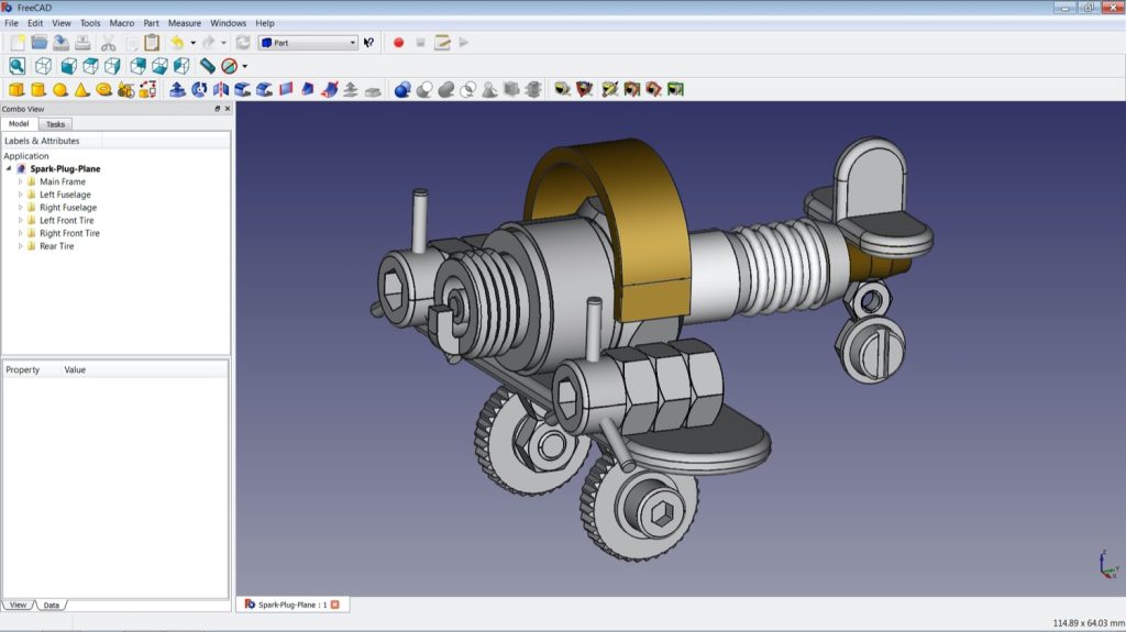
FreeCAD is a completely free, open source CAD program with a basic CAM module attached. It is one of the few free CAD/CAM options that holds up for real machine parts. FreeCAD carries no licensing restrictions, and the free version covers the basic features most simple projects need. It handles 2.5D milling reasonably well and gives beginners a way into CAD design for CNC without a software fee. It falls short of the professional CAD/CAM software once geometry gets complex. For simple parts and smaller CNC projects, though, it does the job.
Hobbyist setups sometimes lean on lighter software such as Carbide Create for routers. That class of tool stays limited outside artistic or one-off work. Easel is another lighter option, combining design and toolpath creation in one place. VCarve Pro suits router work focused on detailed carvings and engraving.
How to Choose the Best CAD/CAM Software
The best CAD/CAM software combination is rarely about which brand tops a review list. A few practical questions narrow the software choice down faster than any comparison chart. No single piece of software fits every shop.
Match Software to Your Machines
Start with the CNC machines on the floor. Three-axis milling and simple turning do not need five-axis, mould-specific CAM software. Paying for capability that nobody uses is money wasted.
Match Software to Your Team
Team size and existing skills matter just as much. A small business rarely benefits from an enterprise CAD/CAM platform that needs a dedicated programmer to run it. A production floor with several CNC machines often outgrows a single-seat software licence within a year.
Match Software to Part Complexity
Simple brackets and plates barely stress the CAM software side of any package. Complex shapes, tight tolerances, or five-axis tool paths reward a CAM program built specifically for that kind of work.
Look Beyond the Licence Fee
Training time, post-processor development, and ongoing support add up. A cheaper CAD program that eats weeks of onboarding is not always cheaper in the end.
Clean geometry inside the CAD files matters more than any brand of software. Teams working with a contract manufacturer such as Aria Manufacturing can usually send a STEP file. That alone skips the CAD/CAM debate entirely. What decides the outcome on the CNC machine is the quality of that geometry. Not the logo on the splash screen.
