

 EU
EUHoles are one of the most common features on a machined part, yet drilling them to a tight tolerance is not simple. Manual drilling creates bottlenecks, uneven hole diameters, and inconsistent positions from part to part. CNC drilling solves this through automated, programmed control of the entire cutting process. This article is written for mechanical engineers, product designers, and procurement managers who specify or source CNC drilling machines as part of their SCM process, and need the practical detail behind how the method works.
What is CNC Drilling?
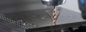
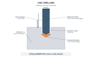
CNC drilling is a computer controlled subtractive production process, distinct from turning, which rotates the workpiece rather than the tool. It uses programmed digital instructions, known as G-code, to drive rotating drill bits into a stationary workpiece. This motion creates holes with a precise, cylindrical profile. The machine follows coordinates established in CAD and CAM software, and the CNC controller regulates spindle speed, feed rate, and plunge depth throughout the cut.
These controls are set in advance and held constant from the first part to the last. This is what keeps hole positioning, depth, and diameter consistent across metals, plastics, and composite materials, run after run.
Most CNC controllers offer a choice of drilling cycles for different hole types. G81 handles a standard, single-pass hole. G82 adds a brief dwell at the bottom of the hole, which improves finish on spot faces and shallow counterbores. G83 breaks a deep hole into a series of pecks, clearing chips between each one so the drill does not clog on long, narrow holes. The programmer selects the cycle based on hole depth and the material being cut. In industrial manufacturing, the process is used primarily on metals and engineering plastics. The same fundamental principle also applies in woodworking and furniture production, where a similar point angle and feed geometry cut into wood rather than metal, though spindle speeds for wood run considerably higher than for metal, since a fast moving edge leaves a cleaner cut and reduces tearing or splintering in the fibres, while feed rate is adjusted to suit the softer material.
How CNC Drilling Machines Work
Digital Modelling and CAM Conversion
Digital modelling forms the foundation of the process. Engineers create 3D part geometry in CAD software, then process the file through CAM software to generate G-code. This code specifies tool paths, coordinate points, spindle speeds, and feed rates.
Common CAD packages used for this stage include SolidWorks, Fusion 360, and Mastercam. The accuracy of this digital model determines how closely the finished part matches the original drawing, since any error introduced here carries through to the physical cut.
Setup and Tooling Installation
Technicians then set up the machine. They select the appropriate drill bits, install them in the spindle tool holders, and clamp the workpiece firmly to the machine bed to prevent shifting during operation.
The choice of clamp depends on part geometry. Flat plates often sit on vacuum fixtures, while irregular castings need dedicated jigs or toe clamps. A poorly secured workpiece is one of the most common causes of hole misalignment on a production floor.
Execution and Plunge Operation
Once running, the machine executes the G-code commands. The spindle positions itself accurately over the specified X and Y coordinates, plunges the rotating bit into the material along the Z-axis to the required depth, then retracts.
On parts with multiple holes, this sequence repeats automatically at each programmed coordinate, without the machine needing to pause for operator input between cuts. Cycle time depends on hole count, depth, and the material’s resistance to cutting. Drilling also rarely stands alone in the process chain. A centre or spotting drill often creates a shallow starting point first, to stop the main drill from wandering off centre, and reaming or tapping follows on holes that need a tight, smooth fit or an internal thread.
Coolant and Chip Management
Coolant jets run throughout the cut. The fluid regulates temperature at the cutting site, extends tool life, and flushes chips out of the hole as it forms.
For deep or narrow holes, chip evacuation becomes more difficult, since debris has further to travel before clearing the hole. Machines built for this task often use through-tool coolant delivery, where fluid is pumped directly through the centre of the drill bit.
Common CNC Drilling Operations
Through Drilling
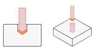
This is the most basic operation. The drill passes completely through the material, leaving an open hole on both faces. It covers most fastener holes, clearance holes, and locating holes on a drawing.
Blind Hole Drilling
Here the hole stops short of the far side of the part. Depth control matters more than with a through hole, since the machine has to plunge to an exact Z-axis value and retract rather than break through. Blind holes are common for tapped holes and dowel locations.
Counterboring and Countersinking
Counterboring cuts a flat-bottomed recess around the top of a hole, usually to seat a socket head cap screw below the surface. Countersinking cuts a conical recess for a flat head screw. Both operations run after the main hole, using a larger tool matched to the fastener head.
Spot Facing
Spot facing machines a small, flat pad around a hole, often on a rough or curved surface such as a casting. This gives a fastener or washer a clean, square surface to seat against, even when the surrounding material is not flat.
Peck Drilling
On deep or narrow holes, the drill plunges in short steps rather than one continuous pass, retracting slightly between each step to clear chips. This is the G83 cycle mentioned earlier, and it prevents the drill from clogging or overheating in holes that run deep relative to their diameter.
Reaming
Reaming follows a drilled hole to bring it to a tighter tolerance and a smoother finish. It removes only a small amount of material, so the original drilled hole needs to be close to size beforehand. This operation matters most on holes that take a dowel pin or a precision shaft.
Tapping
Tapping cuts internal threads into a drilled hole, so it can accept a bolt or screw. On a drilling and tapping centre, this runs as a direct follow-on step after drilling, without moving the part to a separate machine.
What Are the Key Components of a CNC Drilling Machine?
CNC Controller
The CNC controller acts as the central processing unit of the machine. It decodes the G-code instructions and translates them into precise directional movements of the spindle and table.
Most industrial controllers run on established platforms such as Fanuc, Siemens, or Mitsubishi. The controller also stores multiple programs, so a shop can switch between part numbers without reprogramming the machine from scratch.
Spindle
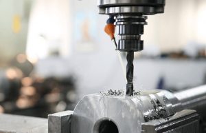
The spindle holds the cutting tool and delivers the rotational torque needed to drive the drill bit through the material. It runs at variable, program controlled speeds while keeping the bit running true.
Spindle speed is usually set in revolutions per minute and adjusted according to the drill diameter and the material being cut. Harder materials generally call for lower speeds, while softer metals and plastics can run faster without overheating the tool.
Machine Frame and Bed
The frame provides structural rigidity and absorbs vibration during cutting. Attached to it is the machine bed, which uses T-slots, vacuum fixtures, or mechanical clamps to lock the workpiece in place.
Frame material affects how the machine performs under load. Cast iron remains a common choice for its damping properties, since it absorbs vibration better than welded steel structures during high speed cycles.
Servo or Stepper Motors and Linear Guides
Servo or stepper motors power the linear movements. Paired with linear guides, they position the spindle along the X, Y, and Z axes with high positional accuracy on every cycle.
Servo motors generally offer finer control and faster response than stepper motors, which is why they are more common on machines handling tight tolerance work. Most servo systems use an encoder mounted on the motor shaft, which senses how far the motor itself has turned rather than where the drill head actually ends up. This works well while the mechanical path stays accurate, but wear or backlash in the linear guides can open a gap between the two, which is why machines that need to catch this directly add a separate linear scale for full closed loop feedback.
Tool Holder
Tool holders clamp the drill bit inside the spindle. Proper tool holding minimises runout and prevents vibration, protecting both the hole quality and the cutting tool itself.
Common holder types include collet chucks, end mill holders, and hydraulic chucks, each suited to a different balance of grip strength and quick change convenience. Selecting the wrong holder for a given drill diameter can introduce runout even when the spindle itself is in good condition. Getting this choice right is essential on tight tolerance work, since even minor runout can push a hole out of tolerance quickly.
Automatic Tool Changer
An automatic tool changer stores a series of drill bits and switches them during a machining cycle. This removes the need for manual intervention when a part requires several hole sizes.
Tool changers vary in capacity, from a handful of stations on a compact machine to several dozen on a production centre handling complex parts. Faster changeover times translate directly into shorter cycle times on jobs with frequent tool swaps.
Coolant and Chip Removal System
This system pumps cutting fluid into the target zone. It cools the tool, lubricates the cut, and flushes chips out of the work area, keeping the process running without interruption.
Chip conveyors carry swarf away from the cutting zone and into a collection bin, which keeps the work area clear and reduces the risk of chips re-entering the cut. On machines running continuously, this system needs regular emptying to avoid blockages.
Types of CNC Drilling Machines
Many holes in modern shops are drilled on general purpose equipment such as a vertical machining centre or a dedicated drilling and tapping centre, which now cover a large share of everyday work. The dedicated machine types below remain common for high volume or specialised jobs, where a purpose built layout still outperforms a general purpose machine.
Upright CNC Drill Press
This machine uses a vertical column layout built for general purpose drilling. It handles medium to large workpieces and remains one of the most common configurations on a shop floor.
This type suits shops running a mix of part numbers, since setup and tool changes are straightforward. It is often the first CNC drilling machine a smaller fabrication shop adds when moving on from manual equipment.
Gang CNC Drilling Machine
Multiple independent drill heads are arranged along a single worktable, each set up for a different step. The workpiece moves from head to head, or the heads index in sequence, so drilling, chamfering, and tapping can happen in one pass without a manual tool change between steps.
This configuration suits parts that need a defined sequence of operations, such as centre drilling followed by through drilling and countersinking, where each head stays dedicated to a single step rather than repeating the same cut.
Gantry or Bridge Type CNC Drilling Machine
An overhead gantry structure traverses the work area, making this type suited to large steel plates and structural beams. The workpiece stays fixed while the gantry carries the drilling head across it.
Because the workpiece does not need to move, this type suits parts too heavy or awkward to reposition repeatedly, such as long structural sections used in bridges and heavy equipment frames.
CNC Beam Drilling Line
This line moves a structural beam through a series of fixed drilling heads, drilling both flanges and the web without the operator repositioning the beam by hand. It suits long structural sections such as I-beams and channels used in steel fabrication.
Sensors check the beam against the part specifications before drilling starts, so hole positions stay consistent even when beam length or camber varies slightly from one piece to the next.
Deep Hole CNC Drilling Machine
This type uses high pressure coolant channels and specialised chip evacuation to cut holes with a high depth to diameter ratio, a process sometimes called gun drilling.
This method is common in hydraulic cylinder and shaft production, where the hole runs most of the length of the part. Depth to diameter ratios in these applications can reach 100:1 or more, well beyond the 8:1 to 10:1 limit of a standard drill cycle. Without adequate coolant flow, chip packing inside the flutes can quickly stall the cut or snap the tool, which is why deep hole drilling relies on high pressure coolant delivered through the drill itself.
Turret CNC Drilling Machine
A rotating turret holds a set of drill bits directly on its face and indexes between them in a fraction of a second, without any tool leaving the turret. This differs from a magazine-style tool changer, which stores more tools but takes longer to swap each one.
Turret capacity is usually smaller than a full tool changer magazine, typically capable of holding a dozen positions or fewer. The trade-off is speed: turret indexing keeps every hole accurate across a complex pattern, even with frequent small tool changes, without the longer swap time a full magazine needs.
Drilling and Tapping Centre
These machines combine drilling and thread cutting in a single machine, producing threaded holes without moving the part to a second station.
This combination is common in automotive and general assembly work, where bolted joints are the norm and threaded holes need to match a consistent depth and thread class across every part.
Multi-spindle Drilling Machine
Several drill spindles are mounted on one head, driving multiple bits into the workpiece at the same time. This suits parts with a repeating hole pattern, such as flanges or panels.
Spindle spacing on these machines is usually fixed or adjustable within a limited range, so the layout needs to match the part’s hole pattern closely before production begins.
Advantages of CNC Drilling Machines
High Precision and Tight Tolerances
Programmed coordinates remove human error from the equation, giving the process a reputation for high accuracy. Each hole lands within a tight tolerance band for position, depth, and diameter, however demanding the drawing’s callouts are. Standard CNC drilling typically holds positional tolerances in the region of ±0.02 to ±0.05 mm, tightening further once a hole is finished with reaming.
This level of control matters most on parts that mate with other components, such as bushings or bearing housings, where even a small deviation can affect the fit of the final assembly.
High Production Efficiency
Automated cycles, together with rapid tool changes and controlled plunge rates, achieve high efficiency compared with manual layout and drilling. This shortens lead times, particularly on parts with a high hole count.
Shorter lead times also give procurement teams more flexibility when scheduling production around other jobs, since a batch that once took days on a manual machine can often run in a fraction of the time. Manual drilling remains slower for these same batches, since each hole depends on an operator repositioning and re-checking the part by hand.
Exceptional Repeatability
Where precision governs a single hole, repeatability governs consistency across the whole batch. Once a program is set, the machine produces thousands of identical holes with minimal dimensional variance from the first part to the last, which lowers scrap rates and cuts down on rework.
Repeatability also simplifies quality control. Once the first few parts off a run pass inspection, sampling checks are usually enough to confirm the rest of the batch, rather than measuring every single part.
Versatility Across Materials
The same process handles steel alloys, aluminium, brass, copper, and engineering polymers, often within the same production run.
This flexibility is useful for assemblies that combine different materials, such as a steel bracket paired with an aluminium housing, since both parts can often be drilled on the same type of machine with a change of tooling.
Complex Hole Geometry
Drilling itself is a straight plunge along the tool’s own axis, but on a multi-axis machine the spindle can be angled or repositioned before that plunge starts. This lets CNC drilling reach angled holes or complex features on more than one face, without repositioning the part by hand.
This distinction matters on parts such as manifolds or brackets, where several holes sit at different angles across the same component. Multi-axis positioning does the aiming, while the drilling cycle itself still runs as a simple, straight-line cut.
Enhanced Workplace Safety
Cutting operations run inside enclosed work areas with safety interlocks. This isolates operators from flying chips, coolant spray, rotating tooling, and excessive noise.
Reduced operator involvement in the cutting process also lowers the chance of repetitive strain injuries associated with manually feeding a drill press through a long production run.
What Are the Applications of CNC Drilling Machines?
Aerospace Industry
Aerospace manufacturers rely on CNC drilling for fastener holes and internal fluid passages in wing spars, turbine components, and structural airframes.
Weight reduction is a constant concern in this sector, so many drilled features double as both a fastening point and a way to remove unnecessary material from a structural part. For example, wing spar assemblies often need hundreds of precisely placed holes across a single panel.
Automotive Manufacturing
Automotive plants use these systems to produce engine blocks, cylinder heads, crankshafts, and brake rotors, components that demand strict geometric alignment.
High production volumes in this sector mean even small efficiency gains per part translate into significant savings across a full model run, which is part of why CNC drilling replaced manual methods early in this industry.
Electronics and PCB Production
Electronics facilities use mechanical CNC drilling for through-holes and mounting locations on printed circuit boards, typically down to around 0.1 to 0.15 mm in diameter. Below that size, laser drilling takes over for micro-vias, since a mechanical bit cannot hold tolerance at that scale.
Board thickness and hole wall quality both affect how well a plated through-hole performs electrically, which is why drilling parameters on PCB work are set and monitored closely.
Construction and Infrastructure
Construction firms depend on heavy duty CNC drilling units to prepare structural steel beams, connection plates, and architectural framing, keeping bolt patterns consistent across a project.
Consistent bolt patterns matter when structural sections are fabricated off-site and need to align accurately during on-site assembly, since a misaligned hole can delay an entire installation schedule.
Medical Device Manufacturing
Medical device makers use precision drilling to manufacture surgical instruments, orthopaedic implants, and diagnostic equipment housings, where smooth surface finishes and tight tolerances are both required.
Traceability is also important in this sector. Many medical device manufacturers log machine, program, and batch data for each drilled component, to support the traceability records required under quality systems such as ISO 13485.
Best Practices for CNC Drilling
Match Speed and Feed to the Material
Spindle speed and feed rate should be set for the specific material and drill diameter, not left at a default. Running too fast on hard alloys shortens tool life quickly, while running too slow on soft materials leaves a rough finish and wastes cycle time.
Centre or Spot Drill Before the Main Cut
Starting a hole with a centre or spot drill gives the main drill a clean, centred starting point. This is especially important on curved or angled surfaces, where a drill bit can wander off position if it starts directly on an uneven face.
Choose the Right Tool Holder for the Job
A collet chuck, end mill holder, or hydraulic chuck each suits a different balance of grip and runout control. Matching the holder to the drill diameter and the tolerance required avoids introducing vibration that the spindle and program cannot otherwise correct.
Manage Coolant Delivery Early in the Program
Coolant needs to reach the cutting edge before heat and chip build-up become a problem, particularly on deep holes. Through-tool coolant delivery is worth specifying at the programming stage rather than adding as an afterthought once tool wear shows up.
Plan Tool Changes and Batch Sequencing
Grouping operations that use the same tool, and sequencing hole patterns to minimise unnecessary spindle travel, cuts cycle time across a production run. This matters more as batch size grows, since small savings per part add up quickly.
Build in Quality Checks at the Right Points
Checking the first few parts off a run against the drawing catches a program or setup error before it spreads across the whole batch. For high tolerance work, spot checks at set intervals through a long run help catch drift from tool wear before it pushes a hole out of tolerance.
Choosing the right machine type, tolerance, and follow-on operations depends on the part in front of you. Aria Manufacturing works with engineering and procurement teams on exactly this kind of decision, from a single prototype to a full production run. Send over a drawing for a concrete answer on machine type, tolerance, and lead time.
