

 EU
EUPicking the wrong lathe tool for a job costs more than the price of the insert. A poor match between tool type, material, and holder costs accuracy fast, showing up as chatter on a long bore, a chipped edge partway through a run, or a part that scraps because a dimension drifted out of tolerance.
This guide is written for machinists, product designers, and procurement managers who choose, compare, or troubleshoot CNC lathe tooling. Whether you are specifying tools for a new part or diagnosing tool wear on the shop floor, the sections below walk through the tool types, materials, and selection criteria you need.
What Are CNC Lathe Tools?

A CNC lathe tool, such as a turning, facing, boring, threading, grooving, or drilling tool, mounts in a turret or tool holder and cuts material from a spinning workpiece. On a CNC lathe, the workpiece sits in a chuck and spins while the tool advances along a programmed path. This differs from a manual lathe, where an operator guides the cut by hand. The automation lets the machine hold tighter tolerances and repeat the same cut thousands of times without drift.
Modern CNC lathes accommodate several different types of cutting tools at once, including turning tools, facing tools, boring bars, threading tools, grooving tools, parting tools, chamfering tools, and drills. These tools mount into an automated indexing turret, a gang style tool block for rapid cross-slide switching, or live tooling holders that add milling, drilling, and tapping to the same setup.
Core Types of Lathe Cutting Tools
CNC lathe tools break into groups by the operation they perform, and a second, simpler way to keep them straight is by where they cut. External, or OD, tools such as turning, facing, and chamfering tools work the outside of the part. Internal, or ID, tools such as boring bars and drilling tools work inside a hole. Specialty tools such as threading, grooving, parting, and knurling tools handle profiles that don’t fit neatly into either category. The sections below cover each type in depth, organized under these three groups.
External (OD) Tools
Facing Tools
Turning tools remove material from a workpiece’s outer diameter and come in two types: roughing tools and finishing tools. Roughing tools use a strong side cutting edge and a heavy feed rate to remove stock fast, since surface finish isn’t the priority at this stage. Finishing tools instead take a light cut at a slow feed with a small nose radius, trading removal rate for a smooth, high-precision surface.
Turning tools also come as left hand or right hand tools. A right hand tool cuts while moving toward the headstock, while a left hand tool cuts in the opposite direction, so shops pick whichever version matches the tool path and the side of the workpiece being cut.
Most turning tools use one cutting edge at a time, though some specialty tools cut two surfaces in a single pass to save cycle time on simple, repeat parts.
Facing Tools
Facing tools feed perpendicular to the lathe’s axis to cut a flat surface on the workpiece’s end. This face often becomes the reference datum that other facing operations and later measurements rely on. A facing tool with the wrong lead angle leaves a slightly convex or concave surface instead of the flat surface it is meant to create, which can throw off every part located against it afterward.
Chamfering Tools
Chamfering tools cut a small angled edge where two machined surfaces meet, removing sharp burrs left after turning, facing, or drilling. A clean chamfer also helps turned parts assemble easily and resists chipping during handling.

Internal (ID) Tools
Boring Bars
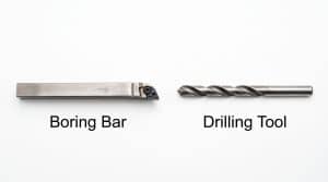
Boring bars reach into an existing hole to enlarge it and improve its roundness. Because a boring bar is long and thin relative to its diameter, rigidity is the main concern. The farther it sticks out past its holder, the more it deflects, and more deflection means more chatter and a worse machined surface.
Carbide shank boring bars address much of this problem, since carbide stays stiffer than steel at the same size and holds its shape under cutting force better than a steel bar does.
Drilling Tools
Drilling tools mount in the tailstock or turret, on center, to pre-drill a hole along the workpiece’s rotational axis. This step usually sets up a later boring or tapping operation, since a straight, centered starting hole lets the boring bar remove stock evenly afterward.
Specialty Tools
Threading Tools
A threading tool’s cutting edge matches a specific thread profile, and most threads use a 60 degree included angle. Because the tool shape defines the thread form, there’s no substitute for the right threading insert. Full profile inserts cut a complete thread form in fewer passes, while partial profile inserts need more passes but cover a wider range of pitches.
Grooving and Parting Tools
Grooving and parting tools use a narrow blade to cut relief grooves into a workpiece surface or part a finished component off the raw bar stock. Because the blade is thin and plunges deep relative to its width, grooving and parting rank among the more failure prone operations on a lathe. Rigid tool holding, a steady feed rate, and plenty of coolant keep the tool from binding or snapping.
Knurling Tools
Knurling tools press a textured pattern into a cylindrical workpiece instead of cutting it. Straight and diamond are the two common patterns, and a diamond knurl crosses two angled lines to produce a raised diamond grid that enhances both grip and aesthetics on handles, knobs, and fasteners. Knurling tools use hardened steel or carbide rollers, and the process work hardens the surface instead of removing material like other lathe cutting tools.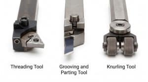
Different Types of CNC Lathe Tool Materials and Coatings
Every tool material trades off toughness, hardness, and heat resistance, and the right choice depends on the workpiece material and the cutting speed.
High-Speed Steel (HSS)
HSS offers strong toughness and impact resistance, and it’s easy to sharpen by hand, which makes it a suitable choice for low speed cutting and simpler jobs. HSS can’t hold an edge at the speeds carbide handles, so on high throughput CNC work, shops save it for specific niches: form tools that would cost too much to reproduce in carbide, or small batches where hand resharpening still makes sense.
Cemented Carbide
Cemented carbide combines extreme hardness with strong heat resistance and is the dominant tool material in modern CNC metal cutting. Carbide typically runs cutting speeds 3 to 5 times higher than HSS, and sometimes more than 10 times higher in optimized high-speed setups, which is a big reason CNC turning cycle times have dropped and shop productivity has climbed so much over the past few decades.
The trade-off is brittleness: carbide chips more easily than HSS under shock loads or interrupted cuts, so machine rigidity and a steady feed matter more when running carbide near its limits. For instance, a general purpose carbide grade running at high speed cuts mild steel efficiently, while stainless needs a tougher, more heat-resistant grade to avoid the same edge failing early.
PVD and CVD Coatings
PVD and CVD coatings add a thin layer onto a carbide insert’s surface. Common coating materials include titanium nitride, titanium aluminum nitride, titanium carbonitride, and aluminum oxide.
These coatings lower friction at the cutting edge, give the insert exceptional wear resistance, and can extend insert life by roughly 2 to 4 times over an uncoated carbide edge, though they don’t change the toughness of the carbide underneath. Titanium aluminum nitride coatings hold up especially well at high temperatures, which makes them a strong choice for dry, high-speed cutting.
Coating choice should match the workpiece material and the main wear mechanism at play, since abrasive wear, adhesive wear, and thermal cracking each respond differently to different coating chemistries.
Advanced Ceramics and CBN
Ceramic and cubic boron nitride (CBN) tools sit at the top for hardness and heat resistance, and shops reserve them for hard turning of hardened steels and high-speed finishing of nickel based alloys and other superalloys.
These tools have the ability to machine parts at hardness levels that would destroy a carbide edge fast, which often removes the need for a separate grinding operation on parts where hard turning works. They’re brittle even by carbide standards, though, so they need a stable setup and struggle with interrupted or unpredictable cuts.
Understanding ISO Standard Insert Shapes and Designation
Indexable turning inserts use standardized ISO codes to define their shape, nose angle, and ideal cutting application. Choosing the right insert shape balances edge strength, cutting resistance, and tool clearance for different turning operations. Below are the most common ISO insert shapes used in CNC turning.
C-Type (80° Rhombic)
The 80 degree included angle gives the C-type insert two strong corners with excellent chip control, which makes it the standard choice for general roughing and heavy turning on steel, stainless, and cast iron. Because the edge sits close to a right angle, it resists chipping under high feed rates and interrupted cuts better than sharper geometries.
Most turning centers default to a C-type insert for straightforward OD work where clearance is not a major concern. The main limitation is access, since the wide included angle struggles on parts with shoulders or contours that need the tool to approach at a steeper angle.
W-Type (80° Trigon)
The W-type insert keeps the same 80 degree strength as the C-type but adds a third cutting edge, so each insert gives three chances to cut before it needs replacing. This lowers the cost per edge on high-volume, general-purpose turning where the insert sees steady wear rather than shock loads. The trigon shape trades a small amount of clearance for that extra edge, so it suits straightforward OD turning more than deep contour work. Shops often reach for a W-type when tooling cost matters as much as raw edge strength.
D-Type (55° Rhombic)
Dropping the included angle to 55 degrees gives the D-type insert noticeably more clearance than the 80 degree shapes, which lets it follow contours and shoulders without the insert body rubbing the part. This makes it a common choice for profiling operations and parts with moderate steps or radii.
The trade-off is edge strength, since the sharper corner chips more easily under a heavy roughing cut, so shops typically save the D-type for finishing passes or lighter roughing. It also handles copy turning and semi-finishing well on parts that mix straight and curved sections.
V-Type (35° Rhombic)
At 35 degrees, the V-type insert, with its narrow, V-shaped point, has the sharpest nose angle of the common ISO shapes, which gives it the most clearance of any rhombic insert and lets it reach into tight corners and narrow profiles that other shapes cannot access. This makes it the go-to choice for precision finishing passes and parts with fine detail near shoulders or grooves.
The sharp nose is also the insert’s weak point, since it chips and wears faster than a C-type or D-type under the same load. V-type inserts run best at lighter depths of cut and finishing feed rates rather than roughing.
T-Type (Triangular)
The T-type insert uses a true triangular shape with a 60 degree angle at each corner, giving it three usable cutting edges and a lower cost per edge than two-edge rhombic inserts. It handles light turning and facing well, especially on smaller parts or shorter production runs where tool life per edge matters more than maximum cutting force.
Because the triangular shape does not offer the same edge strength as an 80 degree insert, shops generally avoid it for heavy roughing or interrupted cuts. It remains a popular, economical choice for general shop work where moderate strength is enough.
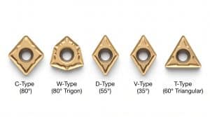
As a starting point: use C-type or W-type inserts for roughing steel and stainless where edge strength matters most, switch to a D-type when the part has contoured or shouldered features that need extra clearance, move to a V-type for precision finishing on tight profiles where clearance matters more than durability, and pick a T-type for light-duty turning and facing where cost per edge outweighs raw strength.
How CNC Lathe Tools Work
On a CNC lathe, the tool removes material from a rotating workpiece through precise, automated motion. The workpiece sits in a spindle chuck and spins rapidly around its axis, which provides the primary cutting motion.
One or more cutting tools, such as turning, facing, boring, or threading tools, mount securely in an automated indexing turret or tool holder.
The machine’s computer numerical control program drives the tool along programmed axial or radial paths at specific feed rates and depths of cut. As the insert’s sharp cutting edge contacts the rotating part, high cutting forces shear away excess stock in the form of controlled chips.
External tools move along or perpendicular to the outer diameter to shape surfaces and flat end faces. Internal tools reach inside pre-drilled holes to enlarge and finish inner dimensions. Special operations like threading and grooving follow precise helical or plunging paths to produce targeted profiles.
By controlling cutting speeds, feed rates, coolant flow, and tool paths automatically, the process delivers consistent dimensions, high surface precision, and efficient production runs.

Common CNC Lathe Tool Problems and Fixes
Most CNC lathe tooling problems fall into four categories: chatter, chipping or abnormal wear, built-up edge, and poor surface finish. Each one traces back to feed rate, cutting speed, rigidity, or insert selection, and each has a specific fix.
Tool Chatter
Chatter, an unwanted vibration in the cut, usually comes from too much tool overhang, not enough rigidity somewhere in the setup, or a mismatch between feed rate and spindle speed. Shorten the tool’s overhang, increase workholding clamping force, and adjust cutting speed up or down depending on where the resonance sits. Dropping spindle speed by ten percent, for example, often breaks up a chatter pattern that a feed change alone won’t fix.
Chipping and Abnormal Wear
Fast chipping or unusual wear traces back to excessive cutting speed, too aggressive a feed rate, or the wrong insert grade for the material. Reducing cutting speed, optimizing feed, or switching to a tougher, more wear-resistant coated insert restores normal tool life almost every time.
Built-Up Edge (BUE)
Gummy materials like aluminum and low-carbon steel can weld onto the cutting edge at moderate-to-low cutting speeds instead of shearing away cleanly. Raising the cutting speed, switching to a smoother-coated or positive-rake insert, and adding plenty of coolant all help stop BUE from forming.
Poor Surface Finish
A rough or inconsistent finish usually comes from a mismatched nose radius, a tool tip that’s off center, or a dull edge. Correcting the tool’s center height, or switching to a finish turning tool built specifically for light, precision passes, typically brings the surface finish back within spec.
Choosing the right CNC lathe tools, and knowing how to troubleshoot them, is the foundation for reliable, high-precision manufacturing. Matching insert geometries and material grades to your specific application pays off directly in faster cycle times, longer tool life, and superior surface finish and part quality.
If you have an upcoming turning project or technical questions, contact our team with your drawings or part specs for expert advice and an instant quote.
-100x100.jpg)