

 EU
EU
Peripheral milling and face milling are both essential cutting operations in precision machining and metal fabrication. Peripheral milling cuts with flutes along the tool’s outer circumference and suits slots and vertical walls, while face milling cuts with teeth on the tool’s end face and suits broad flat areas with high material removal rates.
This guide compares how each method works, where each is used, their advantages and disadvantages, the key differences between them, and how to choose the right milling strategy for a given part and production goal.
Quick Summary Comparison: Peripheral Milling vs Face Milling
| Technical Parameter | Peripheral Milling | Face Milling |
| Active Cutting Edges | Outer cylindrical flutes | Bottom end face inserts |
| Spindle Axis Orientation | Parallel to workpiece surface | Perpendicular to workpiece surface |
| Primary Cutting Force | Radial sideways force | Axial downward thrust |
| Material Removal Focus | Tall vertical walls, slots, profiles | Wide open top surfaces, datums |
| Surface Finish Pattern | Parallel scallop lines | Overlapping circular arc swirls |
| Tool Deflection Risk | High on long tool overhangs | Low due to direct spindle thrust |
| Best Edge Profile | Solid end mills, side-and-face cutters | Indexable shell mills, fly cutters |
What Is Peripheral Milling?
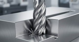
Peripheral milling cuts material using teeth located on the outer cylindrical surface of a rotating cutter. The tool axis runs parallel to the surface being machined.
As part of CNC machining, this milling process is commonly used on metals and plastics, and peripheral milling works along the sides of the workpiece. Side engagement affects chip formation, while chip thickness changes with feed and cutter engagement as radial forces slice away comma-shaped chips along vertical or contoured part faces.
Common Peripheral Milling Operations
- Plain (Slab) Milling: Cuts wide, flat surfaces using the periphery of arbor-mounted cutters on horizontal machines.
- Slot Milling: Forms narrow grooves, keyways, or channels between parallel walls using an end mill or slotting cutters; in peripheral cutting, these tools commonly have 4 to 6 flutes for rigidity and chip control.
- Side Milling: Engages the side cutting edges of a tool to finish vertical walls, steps, or accurate side faces.
- Straddle Milling: Machines parallel vertical faces simultaneously using two spaced-out cutters on a single arbor.
- Profile / Contour Milling: Guides peripheral cutters along complex or irregular digital paths to create detailed edge profiles and complex shapes.
Pros
- High Profile Accuracy: Provides exceptional dimensional control for complex contours, vertical side-walls, and fine profiles in circumferentially tight spaces.
- Deep Wall Efficiency: Machines deep vertical shoulders and complex perimeters efficiently in single axial depth passes.
- Versatile Feature Cutting: Excels at creating specific features like narrow slots, keyways, grooves, and intricate pockets using standard fluted end mills, and suitable milling techniques can also machine contoured surfaces.
- Thermal Management: Concentrates heat inside discarded chips during climb milling, improving tool life and surface quality while preserving part dimensions and holding tight tolerances on outer shoulders.
Cons
- Tool Deflection Risk: Radial sideways forces cause bending on long overhangs, which requires solid machine setup and careful tool geometry to avoid dimensional wall taper, and peripheral milling depends on choosing the right cutting tool, speeds, and depths of cut.
- Inefficient on Broad Flats: Clearing wide flat horizontal surfaces with side flutes takes significantly longer than using dedicated face cutters.
- Vibration Sensitivity: Severe chatter marks occur when cutting deep features without adequate workholding setup rigidity, and conventional milling can worsen chip control and wear in less stable setups.
What Is Face Milling?
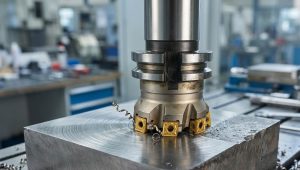
Face milling is a machining process that uses a rotating cutting tool with inserts on the cutter face, with the spindle rotation axis perpendicular to the workpiece surface.
The face milling process is primarily used for creating flat surfaces and often establishes a reference plane before further machining. The swept path of multiple bottom inserts levels the surface as it passes.
Results depend on tool geometry, machine setup, feed, speed, depth of cut, and available machine power, while cutter orientation and how the cutter rotates across the top surface also influence machining performance. For certain side features, cost constraints may favour peripheral milling over switching to a larger face-milling setup.
Common Face Milling Operations
- General Face Milling: Levels wide raw stock and broad flat faces, often with indexable shell cutters or indexable face mills; large diameter cutters are commonly used to cover wide flat areas efficiently in high-volume work.
- Heavy-Duty Face Milling: Hogs off heavy scale from rough castings for heavy stock removal using thick carbide inserts, where insert geometry helps maintain stability during heavy cuts.
- High-Feed Milling: Uses a shallow axial depth with high table feed rates to maximize stock removal.
- Finishing with Wiper Inserts: Burnishes away surface ridges between passes to achieve low surface roughness down to 0.8 µm on moulds and dies or other fine-finish work.
- Side-and-Face Milling: Machines a bottom flat floor and an adjacent vertical shoulder simultaneously.
Pros
- High Material Removal Rate (MRR): Removes heavy material volume across broad flat faces quickly using multi-insert shell mills, typically ranging from 3 to 8 inches or larger; unlike plain milling, face milling is usually preferred in modern setups for broad flat faces.
- Superior Surface Finish: Multiple cutting edges and wiper inserts spread the cut to achieve smooth, flat surfaces consistently, and face milling typically produces smoother surfaces than peripheral milling because the cutter’s outer edges also help refine the texture across wide areas.
- Minimal Vibration: Directing cutting loads straight down into the machine table maximizes spindle column rigidity and reduces workpiece flex.
- Cost-Effective Tooling: Indexable carbide inserts lower operational tool costs because individual worn cutting tips swap out rapidly.
Cons
- Limited Tool Access: Internal pockets, narrow slots, and enclosed contoured walls cannot be accessed by large face cutters.
- No Complex 3D Contouring: The large cutter diameter limits the tool to planar surfaces and shallow steps rather than intricate perimeter shapes.
- Pass Overlap Lines: Overlapping multiple tool passes across wide components can leave subtle visible ridge lines.
- Distortion on Thin Parts: Heavy downward axial thrust causes thin, unsupported sheet metal structures to sag or distort during cutting.
Differences Between Face Milling and Peripheral Milling
How it Works
Peripheral Milling: The cutter axis runs parallel to the surface. Outer flutes engage the workpiece progressively, peeling away metal sideways along the tool path, with chip formation happening along the cutter periphery as the tool advances along walls and profiles.
Face Milling: The cutter axis runs perpendicular to the surface. The flat bottom face rotates across top stock, taking continuous shallow bites to flatten the upper plane, with the cut spread across the cutter face to create flat surfaces ahead of later operations.
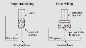
Tool Orientation Comparison
Peripheral Milling: The tool spindle mounts parallel to the finished workpiece plane. The side profile of the cutter directly determines the feature profile.
Face Milling: The tool spindle mounts at a 90 degree angle to the finished plane. The bottom plane of the face milling cutter establishes the part height.
Active Cutting Edge
Peripheral Milling: Cutting action relies almost entirely on peripheral flutes ground along the outer diameter of solid end mills or side cutters, with slab mills also used for broad side or plain peripheral cuts.
Face Milling: Cutting action relies primarily on teeth or indexable carbide inserts mounted flat on the bottom face of shell mills or fly cutters.
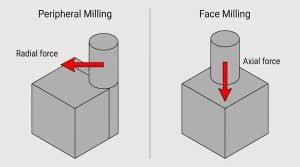
Cutting Force Direction Comparison
Peripheral Milling: Generates strong radial forces pushing sideways, and whether the cutter rotates with or against the feed direction affects chip thickness and cutting force distribution. Lateral loading induces tool bending moments that increase with longer tool stick-out lengths.
Face Milling: Generates dominant axial forces pushing straight down into the machine bed, taking full advantage of machine spindle rigidity.
Cutting Speed and Feed Rate Comparison
Peripheral Milling: Requires controlled feed rate adjustments during deep side cuts to prevent flute overload and bending deflection on slender end mills, and chip thickness should be managed through those feed changes.
Face Milling: Supports fast cutting speed and table feed rate settings across wide areas because multiple inserts share total mechanical stress, and high speed milling can be used on stable machines when better finish and productivity are needed.
Material Removal Rate (MRR) Comparison
Peripheral Milling: Achieves optimal volumetric stock removal when cutting tall vertical walls or deep shoulders in full axial depth passes.
Face Milling: Achieves superior overall volumetric stock removal when roughing broad, open flat surfaces across large cast or forged plates.
Surface Roughness Comparison
Peripheral Milling: Leaves straight, parallel scallop line patterns aligned with the table feed path, which turn into wave lines if chatter occurs.
Face Milling: Leaves overlapping circular arc swirl patterns, which burnish into a smooth finish with low surface roughness when fitting wiper inserts.

Primary Application
Peripheral Milling: Preps keyways, splines, deep pocket vertical walls, turbine blade roots, structural ribs, and complex contoured outer profiles.
Face Milling: Preps engine block deck faces, reference surface datums, mounting pads, hydraulic split lines, and broad flat structural plates, including moulds and dies.
How To Choose Between Face and Peripheral Milling?
When to Use Peripheral Milling
- Choose peripheral milling when the drawing requires machining deep vertical shoulder walls, narrow internal channels, keyways, or enclosed slot features.
- Choose peripheral milling when shaping 2D or 3D contoured outer profiles that require continuous side-flute engagement along a complex path.
- Choose peripheral milling when processing tall side faces where full axial depth passes reduce multi-layer step marks.
When to Use Face Milling
- Choose face milling when establishing true horizontal reference datums, sealing surfaces, or flat locating pads on raw castings.
- Choose face milling when roughing wide flat top faces to achieve high volumetric material removal rate levels rapidly.
- Choose face milling on delicate or thin-bottomed components where lateral radial forces would distort vertical walls.
