

 EU
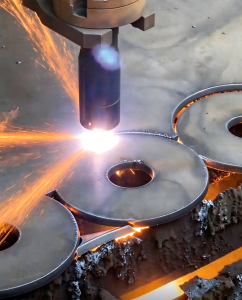
Cutting metal plate into parts means balancing speed, precision and cost. On medium and thick plate, plasma cutting is often the best value. It cuts electrically conductive metal quickly and at low cost.
In industry, most plasma cutting is done on CNC plasma cutters, which follow a programmed path instead of a hand-held torch.
This guide looks at plasma cutting from an industrial point of view and covers how the plasma cutting process works, types, cut materials and thickness limits, pros and cons, and applications.
It also compares plasma with laser, waterjet and oxy-fuel, and ends with design tips and cost factors.
What Is Plasma Cutting?
Plasma cutting is a thermal cutting process that uses a jet of high energy ionized gas. Plasma is often called the fourth state of matter. When a gas absorbs enough energy, it becomes ionized and conducts electricity.
A plasma cutter forces gas through a narrow nozzle and passes an electric arc through it. The result is a focused, high temperature jet, hotter than 20,000°C, that cuts metal plate.
Plasma cutting is also called plasma arc cutting. It is mainly used for through cuts, producing flat 2D profiles that often go on to bending, welding or CNC machining.
How the Plasma Cutting Process Works
The cutting process has two stages: the arc forms, then the plasma jet melts and clears the metal.
Gas Ionization and Arc Formation
Compressed air or another gas, such as nitrogen, oxygen or argon, flows into the plasma torch.
Next, the power supply strikes a pilot arc, a high voltage electrical arc between the electrode and the nozzle inside the plasma torch. The pilot arc ionizes the gas but does not cut.
Older systems lit the pilot arc with high-frequency starting, which can interfere with nearby electronics and CNC controllers. Most modern systems use a blowback pilot arc method instead. The electrode briefly touches the nozzle, then springs back to draw the arc.
When the torch comes close to the plate, the pilot arc jumps to the workpiece and becomes the cutting arc. This is the transferred arc.
This is why plasma cutting only works on electrically conductive materials. The workpiece has to complete the electrical circuit.
Melting and Ejection
The nozzle squeezes the plasma arc into a narrow column, which raises its energy density. The high temperature plasma melts the metal on contact.
A high pressure stream of gas then blows the molten metal out of the bottom of the cut. The gap the plasma stream leaves behind is called the kerf.
Molten material that solidifies again on the bottom edge is called dross.
On CNC plasma cutters, each part starts as a CAD drawing, usually a DXF file. CAM software turns it into G-code with the cutting path, speed and pierce points.
The CNC controller then moves the cutting head along that path. It sets the cutting speed, slows down in corners and switches the arc on and off at each point.
Components of CNC Plasma Cutters
Plasma Torch and Consumables
The torch head holds the consumables: the electrode, nozzle, swirl ring, shield and retaining cap.
The electrode carries a hafnium insert that emits the plasma arc. The nozzle shapes it, and the swirl ring spins the gas to keep the plasma arc centered.
Power Supply and Air Compressor
The power supply converts AC line power into constant DC current and supplies the high voltage needed to start the arc. Its amperage sets how thick the plasma cutting system can cut.
Air plasma cutters also need an air compressor. It must deliver enough flow at a steady pressure.
Compressed Air and Gas Regulation
Compressed air must be clean and dry. Water or oil in the line shortens consumable life. Most shops fit filters and a dryer between the compressor and the plasma cutting machine.
Dual gas systems also use bottled compressed gas. A gas console regulates pressure and flow for both the plasma gas and the shield gas.
Torch Height Control and Cut Quality
Torch height control (THC) keeps the plasma torch at the right distance from the plate. It reads arc voltage and raises or lowers the torch to hold the gap.
Height has a direct effect on cut quality. A torch set too high increases bevel. A torch set too low causes dross and nozzle damage.
Cutting Table and Work Clamp
The cutting table supports the plate on replaceable steel slats. A water table or downdraft table controls fumes and sparks. The work clamp connects the plate to the power supply and closes the electrical circuit.
Types of Plasma Cutting
Plasma cutters are grouped by how the torch moves, which gases it uses and what cut quality it reaches. These groups overlap. High definition plasma, for example, is a form of mechanized plasma cutting that uses two gases.
Other variants include water injection plasma cutting, which uses water to constrict the arc. Mechanized systems can also carry a bevel head for weld preps, and torches can be set up for plasma gouging.
Handheld vs CNC Plasma Cutting
Handheld plasma cutters are portable and quick to set up. They suit repair and site work.
CNC plasma cutting, also called mechanized plasma, mounts the plasma cutting head on a gantry or robot. Parts are cut from a program, so the last piece matches the first.
Parts for mass production are almost always cut this way.
Air Plasma Cutting vs Dual Gas Plasma Cutting
Air plasma cutting uses compressed air for both cutting and cooling.
Dual gas plasma cutting supplies a separate plasma gas and shield gas. The shield gas surrounds the plasma arc, protects the cut edge and cools the nozzle. It gives better edge quality, especially on aluminum or stainless steel.
| Plasma Gas | Shield Gas | Best For |
| Air | Air | Carbon steel, stainless steel and aluminum |
| Oxygen (O2) | Air | Mild steel, with a smooth, weldable edge and little dross |
| Nitrogen (N2) | Air or N2 | Stainless steel and aluminum, thin to medium thickness |
| F5 (95% N2, 5% H2) | N2 | Thin stainless steel, with a bright, low-oxide edge |
| H35 (65% Ar, 35% H2) | N2 | Thick stainless steel and aluminum |
These are typical combinations. Gas options vary by machine, so check the manufacturer’s cut charts.
Conventional Plasma Cutting vs Precision vs High-Definition
Conventional plasma cutting uses a wider plasma arc and a simple gas setup. It is fast and low cost but leaves the most bevel. Precision plasma narrows the plasma arc and often runs oxygen on mild steel.
High definition plasma cutting constricts the plasma arc further with special nozzles and dual gas. It delivers precision cuts combined with high speed, with edges close to laser cutting quality on medium plate.
| Type | Edge Quality | Typical Use |
| Conventional | Wider kerf, most bevel | Blanks, structural parts, handheld work |
| Precision | Narrower kerf, less bevel | Brackets and frames with moderate tolerances |
| High-definition | Narrowest kerf, near-square edge | Parts that go straight to welding or assembly |
As a rough guide, conventional plasma holds around ±0.5 to 1 mm and high-definition plasma around ±0.25 to 0.4 mm. Edge quality on thermal cuts is often graded to ISO 9013, which rates squareness and surface roughness.
Plasma Cut Materials and Thickness
Any electrically conductive metal can be plasma cut.
Compatible Metals
Mild Steel and Carbon Steel: These are the most common plasma cut materials, with the cleanest edges on oxygen.
Stainless Steel: It cuts well with nitrogen or argon-hydrogen, which limit edge oxidation.
Aluminum: It cuts fast but needs higher gas flow, since it draws heat away from the cut.
Copper and Brass: Plasma cutters handle these highly reflective materials better than CO2 laser cutters.
Cast Iron: It cuts readily but leaves a hard, brittle edge.
Galvanized Steel: It cuts like mild steel, but the zinc fumes must be extracted.
Abrasion-Resistant Plate: Wear plates such as AR400 cut faster and cooler than with oxy-fuel.
Titanium: It can be cut, but the edge usually needs machining before welding.
Thickness Limits by Amperage
Maximum material thickness rises with the amperage of the plasma cutting system. Ratings give a recommended cut for production speed and good quality, and a severance cut for the most it can cut through.
| Amperage | Recommended Cut | Severance Cut |
| 30 to 45 A | Up to about 16 mm | Up to about 30 mm |
| 65 to 85 A | About 20 to 25 mm | About 32 to 38 mm |
| 105 to 125 A | About 32 to 38 mm | About 50 to 57 mm |
| 200 A and above | 50 mm and up | Up to about 150 mm |
These are typical ranges for air plasma on mild steel. Actual capacity depends on the machine, material and consumables.
Piercing to start a cut also takes more power than cutting from an edge, so CNC parts are often limited to thinner plate.
Materials Plasma Cannot Cut
Plasma cutting can only cut conductive materials. This rules out wood, plastic, glass, stone, ceramics and most composites. Laser cutting or waterjet cutting suits these materials instead.
Plasma Cutting Pros and Cons
Advantages
Versatility: Plasma cutting handles any conductive metal, including aluminum and stainless steel that the oxy-fuel process cannot cut.
Speed: It cuts medium plate much faster than oxy-fuel cutting, with no preheating.
Repeatable CNC Accuracy: Every part on a CNC plasma cutting machine follows the same path, so complex shapes stay consistent across a batch.
Lower Operating Cost: Plasma cutters cost less to buy and run than laser cutters or waterjets on thicker plate.
Smaller HAZ Than Oxy-Fuel: At the same thickness, the faster cut usually leaves a smaller heat-affected zone.
Thick Plate Capability: It handles thick metals, and mid-range systems cut 25 to 38 mm at production speed.
Cuts Rusty or Painted Metal: Rust, mill scale and paint do not stop the cut.
Portable Handheld Units: Handheld plasma cutters run on site from a power outlet and a compressor.
Limitations
Edge Bevel: Cut edges usually have a slight angle, often around 3 to 8 degrees per side on conventional systems and 1 to 3 degrees on high-definition systems.
Dross Formation: The wrong cutting speed or torch height leaves molten metal on the bottom edge that needs grinding.
Lower Precision and Wider Kerf Than Laser: Laser cutting often holds around ±0.1 mm, while the plasma kerf is typically about 1.5 to 4 mm wide.
Poor Small-Hole Quality: On conventional systems, holes smaller than the plate thickness come out tapered, though high-definition systems with hole-cutting routines do much better on carbon steel.
Thin Sheet Distortion: The high temperature can warp sheet metal thinner than about 3 mm.
Hardened Cut Edge: Cutting steel with air or nitrogen can leave a nitrided edge, which may cause weld porosity if the edge is not cleaned.
Fast Consumable Wear: Electrodes and nozzles in the torch head wear with every pierce.
Conductive Metals Only: Non-conductive materials cannot be cut.
Fumes, Noise and UV Radiation: The process needs fume extraction, hearing and eye protection, and care with high voltage and hot sparks that can cause shocks or fires.
Plasma Cutting Applications
Plasma cutting sees widespread use wherever steel plate is turned into flat parts in volume.
Heavy Equipment: Frames, brackets and wear plates for excavators, cranes and loaders.
Construction Steel: Base plates, gussets and connection plates for steel structures.
Shipbuilding: Hull plates, bulkheads and deck sections cut from thick metals.
Agricultural Machinery: Chassis parts, hitch plates and blades for tractors and implements.
HVAC and Ductwork: Duct sections, flanges and fittings cut from galvanized sheet metal.
Automotive and Truck Frames: Crossmembers, frame rails and mounting brackets for trucks and trailers.
Mining Equipment: Buckets, liners and chutes cut from abrasion-resistant plate.
Oil and Gas Equipment: Flanges, skid frames and beveled pipe ends.
Metal Signage and Art: Custom signs, lettering and decorative panels with detailed profiles.
Repair and Demolition: Handheld cutting of damaged parts, scrap and old structures on site.
Plasma Cutting vs Laser vs Waterjet vs Oxy-Fuel
Plasma cutting, laser cutting, waterjet and oxy-fuel cutting are the four common ways of cutting metal profiles.
| Plasma | Laser | Waterjet | Oxy-Fuel | |
| Materials | Conductive metals | Metals and some non-metals | Almost any material | Carbon and low-alloy steel |
| Best Thickness | Medium to thick plate | Thin to medium sheet | Thin to very thick | Thick plate |
| Accuracy | Moderate | Highest | High | Lowest |
| Cut Quality | Good, slight bevel | Excellent, straight edge | Smooth, no heat marks | Rough, wide kerf |
| Heat-Affected Zone | Moderate | Small | None | Large |
| Cutting Speed | Fast on medium plate | Fastest on thin sheet | Slowest | Slow, needs preheat |
| Relative Cost | Low | High | High | Lowest |
Design Tips for Plasma Cut Parts
A few design choices help plasma cutters produce cheaper, more accurate parts. Treat these as starting points that vary with plate thickness, machine and tolerance.
Minimum Hole Size: Keep hole diameters at least equal to plate thickness, and machine smaller holes after cutting.
Feature Size and Hole Spacing: Keep slots, tabs and gaps between holes at least one plate thickness wide.
Kerf Compensation: Draw parts at final size and let the CAM software offset the path by half the kerf.
Lead-In and Lead-Out Placement: Place lead-ins in scrap areas or on non-critical edges, because they leave a small mark.
Thin Sheet Distortion: For sheet under about 3 mm, use wider webs and small tabs, or consider laser cutting.
Plasma Cutting Cost Factors
Plasma cutting is priced mainly on machine time, consumables and material.
Material Type and Thickness: Thicker plate cuts slower and wears consumables faster.
Cut Length and Pierce Count: Cutting distance sets machine time, and every pierce adds wear.
Amperage and Cutting Speed: Higher-amperage plasma cutters cut thick plate faster but use more power and consumables.
Consumables and Gas: Oxygen and H35 cost more to run than compressed air.
Nesting Efficiency: Tight nesting fits more parts on metal sheets and cuts waste.
Order Quantity and Setup: Programming and setup costs are spread across the batch.
Tolerance and Cut Quality Requirements: Tighter tolerances may call for high-definition plasma or laser cutting.
Secondary Operations: Dross removal, grinding and machining add labor after cutting.
Conclusion
Plasma cutting is a fast, low-cost way to cut conductive metal. It works best on medium to thick steel, where speed and cost matter more than laser-level precision.
Edge bevel, kerf width and small holes are its main limits, and good design avoids most of them.
For parts that need cutting plus bending, welding or CNC machining, Aria’s sheet metal fabrication team can review your drawings and recommend the right cutting process.
