

 EU
Plunge milling is an alternative to side milling for deep slots, grooves, cavities, and tall walls. The cutter feeds straight down along the Z-axis instead of making lateral passes. This sends the cutting force up into the spindle, which is usually the stiffest direction on a machine. The tool bends less, and vibration and chatter drop. Deep roughing becomes more stable as a result. This guide covers how the process works, the cutters it uses, and how it compares with conventional milling. It also looks at the advantages, the limitations, and when to choose it.
What Is Plunge Milling?
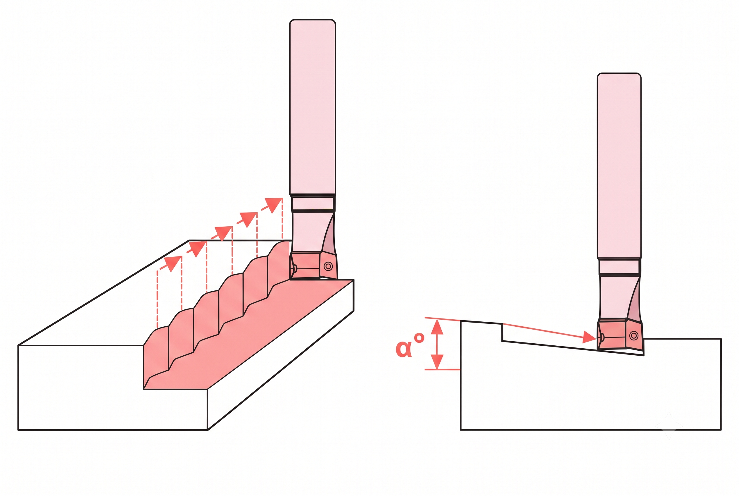
Plunge milling is a roughing method where the cutter feeds straight into the workpiece, parallel to the spindle axis. It is also called plunge roughing. The tool moves down, cuts, and retracts along the Z-axis. It then steps over in X or Y and plunges again. Repeated overlapping plunges clear out a slot, pocket, or cavity.
Conventional milling removes material through lateral engagement, where the side of the cutter does the work. In plunge milling, the end cutting edges do most of the cutting. This puts the load along the tool axis, and on most machines the Z-axis is the stiffest direction. The motion looks like drilling, but the cutter is not making one hole. It is clearing an area.
The programmer sets the individual points where each plunge lands. The step-over must be small enough that no uncut material is left standing between them. The method suits deep pockets, tall walls, and long tool reach. It leaves a scalloped surface, so finishing operations follow to bring the part to size.
https://youtu.be/tlckRNfeXYI?si=j6QyJYPcbah3tLYK
How Plunge Milling Works
Plunge milling works differently from side or face milling. The tool engages the workpiece along a vertical path instead of cutting across it. Three behaviors define the process.
Axial Force Shift
In side milling, the cutting force pushes against the side of the tool. This radial load bends the tool and holder, which leads to chatter and limits depth of cut. Plunge milling directs most of the force along the tool axis instead. On most machines, the Z-axis is the stiffest direction, so the force travels up into the spindle rather than bending the tool. Deflection drops, and long reach becomes less of a problem.
Step-and-Repeat Motion
The cutter plunges to the full depth of the cut, retracts, steps over sideways in X or Y, and plunges again. Repeating this builds a row of overlapping cuts, and rows repeat until the slot or pocket is open. The plunge tool path is a simple pattern of points, much like a drilling cycle. CAM support varies. Some plunge cycles only handle flat-floored features, so confirm the cycle is suitable for the shape of the part.
Step-over is the sideways distance between plunges. It is usually set as a share of tool diameter, then adjusted for reach and insert size. Different cutters need different spacing. Feed per tooth and other parameters should follow the tool maker’s data. On the retract, many programs move the cutter slightly away from the wall first, so it does not rub or re-cut. The overlapping plunges create a scalloped surface, so a finishing pass cleans up the walls afterward.
Interrupted Boring Effect
Each plunge works much like an interrupted boring cut. Plunge cutting happens at the end of the tool, and every plunge is a separate cut. The cutter enters the material, cuts, and leaves before the next one starts. This repeated entry and exit puts shock on the cutting edges. A rigid toolholder and a strong insert grade help the tool handle it.
Common Plunge Milling Cutters
Four cutter types cover most plunge milling work. The right choice depends on feature size, depth, insert geometry, and how much stock must come out. Whatever the cutter, a short, rigid holder keeps the setup stable.
Indexable Square-Shoulder Plunge Mills
These are the standard roughing cutters for plunge milling. They carry replaceable inserts on a steel body, with an entering angle close to 90 degrees. The cutter takes strong axial loads and cuts a near-square shoulder, which suits deep slots, stepped cavities, and 90-degree internal walls. A worn edge is fixed by indexing the insert instead of replacing the cutter. Internal coolant helps in deep cavities because it pushes chips out of the cut. Wall cleanup follows the roughing pass.
Indexable Round-Insert Button Cutters
Button cutters use round inserts. The round edge has no weak corner, and the cutting load spreads along the curved edge. One shop reported that round inserts chattered less than flat-bottom inserts in plunge roughing. Insert diameter limits how far the cutter can step over, so it must be part of the tool path plan. The round shape also leaves a different scallop pattern on the floor.
Solid Carbide Plunge End Mills
Solid carbide end mills made for plunging suit smaller cavities, narrow slots, and deep corners that a large indexable cutter cannot reach. The cutter must be center-cutting, because many end mills cannot cut at their center and cannot take a plunge. Some solid tools can run with long overhangs. Check the tool maker’s guidance on end geometry before plunging with a general-purpose end mill.
High-Feed / Center-Cutting Indexable Drills
Center-cutting indexable drills can plunge straight into solid stock. They are often used to open a starting hole, so that a non-center-cutting cutter can enter the pocket without cutting at its center. Conventional twist drills can also rough out material by chain drilling. The conical point tends to wander when holes overlap too much, and it leaves a scalloped floor. Flat-bottom drills avoid the floor problem.
Plunge Milling vs Conventional Milling
Plunge milling and conventional milling remove material in different ways. The table compares them on the points that matter when choosing a roughing strategy.
| Plunge Milling | Conventional Milling | |
|---|---|---|
| Primary Motion and Feed Speed | Z-axis plunges, then a sideways step-over. Feed per tooth is often lower. | Continuous cutting across the X/Y plane. Feed can run higher in stable conditions. |
| Primary Force Vector | Mostly axial, into the spindle. | Mostly radial, against the side of the tool. |
| Vibration / Chatter | Lower risk with long reach or deep cuts. | Higher risk with long overhang or deep cuts. |
| Chip Thickness Pattern | Set by feed per tooth. Short, interrupted cuts. | Varies along each cut, from thin to thick. Steadier chip flow. |
| Best Suited For | Deep pockets, slots, and unstable roughing. | Open surfaces, shallow cuts, contours, complex shapes, and finishing. |
The two methods work together more often than they compete. Plunge milling removes bulk stock from deep areas and leaves a consistent allowance on the walls. Conventional milling then brings the walls and floor to final size.
Advantages of Plunge Milling
Plunge milling helps most when side milling runs into limits of tool reach, machine rigidity, or power.
- Reduced Tool Deflection: Side load bends a long tool away from the cut. Plunge milling sends the force along the tool axis, which a tool resists far better. The cutter holds its position at long reach.
- Elimination of Chatter and Vibration: Less side load means less bending to feed chatter. Plunge milling can calm tall thin walls and deep slots where side milling struggles. It does not remove chatter completely, since a weak holder or long tool stick-out can still cause it.
- Lower Horsepower and Power Demands: Plunge milling can run on machines with limited spindle power. Short, controlled cuts keep the tool from fighting side forces. It also helps when spindle speed is the limit.
- Extended Spindle and Tool Life: The tool sees less uneven side loading, and the spindle takes the load along its axis. Tool life still depends on chip evacuation and insert grade.
- Effective on Difficult Materials: Titanium, nickel alloys, stainless steel, and hardened steel produce high cutting forces and heat generation. Radial force climbs fast with engagement in these materials, and plunge milling keeps it low. Insert grade and coolant still matter.
- Improved Stability on Lightweight Equipment: Light milling machines, older mills, and mill-turn live tooling often lack rigidity in X and Y. Most are strongest along Z, and plunge milling uses that. It lets them rough features that would otherwise chatter.
Limitations of Plunge Milling
Plunge milling solves a specific problem. Outside that problem, it has costs.
- Rough Surface Finish: Overlapping plunges leave scallops on the walls and floor. Finishing operations are always needed, and a semi-finishing pass may come first if the scallops are deep.
- Poor Chip Evacuation: In a deep or blind cut, chips collect at the bottom of the pocket. Coolant, air blast, and flute space all matter. Internal coolant helps most. On a horizontal machine, chips fall away from the cut. A vertical machine may need stronger coolant or an air blast.
- Re-Cutting Risk: Chips left in the cut get cut again. This adds heat, chips inserts, and hurts surface finish. A straight retract along the wall can also rub or re-cut, so the tool path should move the cutter off the wall first.
- Inefficient on Rigid Setups: With short reach and a rigid setup, side milling works fine. High-feed milling and adaptive roughing are also often faster than plunging, and they usually leave a better surface. The constant retracts and repositioning add non-cutting time.
- Dead Center Cutting Issue: Many end mills and indexable cutters cannot cut at the tool center. They need a starter hole or a ramped or helical entry. A non-center-cutting tool also cannot cut on a downward slope. Planning the step-over so no center cutting is required avoids the problem.
- Axis Vibration: A worn Z-axis, weak toolholder, or loose clamping can still cause vibration under axial load. Repeated entry and exit also put shock on the cutting edges. The setup must stay rigid.
When to Use It
Plunge milling fits when side milling hits a limit. Material alone does not decide it. Aluminum and steel parts with deep features benefit as well.
Deep Pockets and Cavities
Long tool reach makes side milling bend the cutter. Plunge milling removes the bulk of the stock with less deflection. Leave a finishing allowance for a later pass.
High-Chatter Conditions
Tall thin walls and deep slots often chatter under side load. Plunge milling can allow roughing without it. It is not a total cure, since a finishing pass must still remove the scallops.
Limited Spindle Power
On lighter machines or machines with a low top speed, plunge milling can rough effectively. Short, controlled cuts keep power demand down. Plunge feeds and speeds may run a little slower than high-speed machining. If spindle speed limits the machine, plunge milling can still give the best removal rate.
Restricted Areas
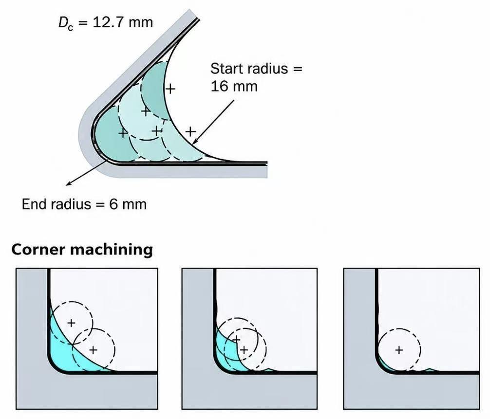
Deep internal corners and closed slots are hard to reach with a short, rigid tool. Plunge milling can clear this rest material before a finishing tool cleans up the wall.
Difficult-to-Machine Materials
Titanium, nickel alloys, and stainless steel build up radial force quickly. Plunge milling keeps it lower during roughing. Insert grade and coolant still need to match the material.
Other Common Types of Milling
Plunge milling is one of several milling methods. These four are common in CNC shops.
- Face Milling: The cutter axis is perpendicular to the workpiece, and the cutter cuts mainly with its face. A large face mill can cover the full width of a part in one pass. It is used to flatten surfaces and produce a smooth, flat finish.
- Side Milling: The cutter cuts with its periphery along the side of a wall or slot. It is the main alternative to plunge milling, and the method most affected by deflection at long tool reach.
- End Milling: An end mill cuts with both its end and its sides. It handles slots, pockets, profiles, and contours, and it is often used for finishing after roughing.
- Thread Milling: A rotating tool follows a helical path to cut threads in a hole or on an outside diameter. It suits threads that are hard to tap, such as large diameters or tough materials.
Most parts need more than one of these methods. A typical sequence roughs with plunge or side milling, then finishes with end milling.
Plunge milling is a roughing method for deep pockets, tall walls, and long tool reach. It reduces deflection and chatter by sending the cutting force along the tool axis. It leaves a rough surface, so a finishing pass always follows. If your part has deep cavities or hard-to-reach features, send your drawings to Aria Manufacturing at madearia.com for a quote.
