

 EU
EUPocket milling is a CNC machining operation that removes material from within a defined boundary to create a recessed cavity in a part. It is one of the most common operations in custom metal and plastic machining, yet it is also one of the easiest to get wrong.
A cavity that looks straightforward in a CAD file can turn into a source of chatter, tool breakage, or dimensional drift once it reaches the machine. Engineers, product designers, and procurement managers benefit from understanding how pocket milling actually behaves, not just what it produces.
What Is Pocket Milling?

Pocket milling refers to the process of removing material from inside a boundary to create a recessed cavity, slot, or similar feature in a workpiece. Unlike facing or contour milling, which shape the outside of a part, pocket milling works from the inside out, leaving walls and a floor behind.
In CNC milling, pocket milling typically sits between rough stock removal and final finishing, following an initial facing or profiling pass.
A pocket rarely comes out right in one pass. Roughing clears the bulk of the material, and a lighter finishing pass cleans up the surfaces that need to meet tolerance.
Aluminium alloys such as 6061 and 7075 are the most common materials for pocket milling, since they tolerate higher feeds and spindle speed while clearing chips easily. Stainless steel, brass, and engineering plastics also see regular pocket work, though each brings its own constraints around heat, tool life, and chip control.
Deep pocket milling, where the cavity depth runs several times the tool diameter, is where these material differences start to matter most.
Process and Strategy
Balancing Cycle Time Across the Rough Cut to Final Pass Sequenc
Cutting a pocket in one continuous pass at final size is rarely a good idea. Most programmers split the job into a roughing stage and a finishing stage, and the balance between the two determines not only total cycle time but also overall machining time.
Roughing removes material quickly rather than accurately. A common approach leaves 0.2 to 0.5 millimetres of remaining stock on the walls and floor, just enough to guarantee the finishing pass has something clean to cut rather than air.
Pushing the roughing tool too aggressively saves time on paper but often costs more later. Heavy engagement increases tool wear and can leave enough deflection that the finishing pass has to remove more material than planned.
Finishing then takes over with a lighter cut, usually at a slower feed and sometimes a slightly higher spindle speed, to bring the pocket to its final dimensions and surface finish. Skipping this step, or treating the roughing pass as good enough, is one of the more common reasons a pocket comes off the machine with visible tool marks or inconsistent wall thickness.
Cycle time is not purely a function of how fast the roughing pass runs. Design and process choices that avoid extra passes also help control overall machining time and cost.
A rushed roughing stage that forces rework or an extra finishing pass often ends up slower overall than a slightly more conservative one done right the first time, extending lead time rather than shortening it.
Controlling Stepdown in Deep Pockets
Stepdown, the axial depth removed in each pass, has a direct relationship with tool rigidity. As pocket depth increases, the tool has to extend further into the cavity, and that extra length reduces how much force the cutter can handle before it starts to deflect or chatter.
For pockets within roughly three times the tool diameter in depth, a standard stepdown of 0.5 to 1 times the tool diameter usually works without much drama. Beyond that, particularly in deep pocket milling where depth stretches past four or five times the diameter, taking more passes becomes necessary even though it adds cycle time.
The alternative, pushing a large stepdown through a long, thin tool, tends to produce a tapered wall or a rough floor rather than any real time saving.
A useful rule of thumb is to treat the depth-to-diameter ratio as the main warning sign. Once it climbs past four, most shops start reducing stepdown, slowing the feed, or switching to extended reach tools designed for greater stiffness rather than continuing with standard cutting parameters.
Safe Entry Approaches Before the First Cut
How and where a tool enters the material matters more than it might seem. Straight plunge milling puts enormous axial load on the tool tip, since the centre of most cutters does not cut efficiently, if at all. This approach works only with specific centre-cutting tools and shallow depths, and even then it can break tools or leave a rough mark at the bottom of the entry point.
Ramp entry solves this by moving the tool down at a shallow angle, typically two to five degrees, while it advances forward. This spreads the cutting load between the axial and radial directions rather than concentrating it straight down the tool axis, and it remains one of the most widely used entry methods for pocket milling.
Helical entry takes a gentler path still. The tool spirals downward using helical interpolation, gradually working its way to depth rather than plunging or ramping in a straight line. This method suits harder materials and deep pockets particularly well, since gradually increasing tool engagement reduces shock loading on the cutter.
It does require enough room inside the pocket for the helix diameter, generally around 50 to 75 percent of the pocket width. Very narrow cavities may need a different approach or a smaller diameter tool for the entry move alone.
Types of Pockets
Fully Enclosed Cavities
A closed pocket sits entirely inside the part, with material surrounding it on every side. There is no natural opening for the tool to approach from the edge, so the cutter has to create its own entry point, usually through a ramp or helical move rather than a straight plunge.
Chip evacuation tends to be harder here than in other pocket types, simply because the chips have fewer places to go.
Enclosed housings, mounting recesses, and mould cavities are typical examples. All of them generally need both a roughing pass and a dedicated finishing pass to achieve the required dimensional accuracy.
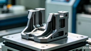
Cavities Open to One Edge of the Part
An open pocket breaks through at least one side of the part rather than sitting fully enclosed. This changes the machining behaviour in a few practical ways.
The tool can often enter from the side instead of ramping vertically. Chips clear more easily since there is an open path out of the cavity, and the CAM software typically starts the toolpath from outside the part and works inward.
Weight reduction cutouts, access channels, and stepped features fall into this category. Because the geometry is less constrained than a closed pocket, open pockets are usually somewhat faster and more forgiving to machine, particularly at greater depth.
Cavities Containing Raised, Unmachined Features
Some pockets are not simply hollow. They contain an island, a block of remaining material that stays untouched inside the cavity while everything around it is cleared. Bosses for fastener holes, alignment posts, and structural ribs are common internal features a designer might specify within a pocket.
Machining around an island introduces complex geometries into the toolpath. The cutter has to clear the surrounding area without colliding with the raised feature or leaving excess material near its base.
Modern CAM software handles this automatically in most cases, treating the island as an exclusion zone. The added geometry still increases programming time and can limit which toolpath strategies are practical for that particular pocket.
Tool & Parameter Selection
Choosing End Mill Flute Count for the Cavity
Flat end mills handle the majority of pocket work, though the right flute count depends heavily on the material being cut. Aluminium generally favours two or three flute tools, since fewer flutes leave more room between cutting edges for chips to clear before they pack into the cavity and cause recutting.
Steel and other tougher alloys usually call for four flute tools instead. The extra flute adds rigidity, which results in less deflection along the tool. This helps hold tolerance and improves the finish on pocket walls, though it does reduce chip clearance slightly compared to a tool with fewer flutes.
Flute length needs to clear the full pocket depth as well, since a flute that stops short leaves the shank rubbing against the pocket wall.
Corner radii also constrain tool choice directly. If a pocket has a tight internal corner, the cutter has to be small enough to reach it, regardless of what flute choice would otherwise be ideal for the material.
Setting Stepover and Radial Engagement
Stepover, the radial distance the tool moves between passes, controls the cutting forces the cutter experiences at any given moment. During roughing, a stepover of 30 to 50 percent of the tool diameter is typical, balancing material removal rate against the risk of overloading the cutting tool.
Finishing passes drop this figure sharply, often down to 5 to 10 percent, since the goal at that stage is a clean, accurate wall rather than fast material removal.
Pushing stepover too high during roughing is one of the more common causes of chatter. It increases radial pressure on a tool that may already be working at a long stickout inside a deep pocket, making it harder to avoid deflection.
Matching Spindle Speed and Feed to Material Hardness
Feed rate and spindle speed need to move together with the material being cut, not just with the tool manufacturer’s default chart. The underlying goal is steady, consistent chip formation.
Too low a feed and the tool rubs rather than cuts, which generates heat and accelerates wear. Too high a feed and the milling cutter can overload the moment it hits a corner or a sudden increase in engagement.
Aluminium generally tolerates higher spindle speeds than steel, particularly with smaller diameter tools, since it clears chips easily and does not build up heat as quickly at the cutting edge. Steel typically needs the opposite adjustment, running at lower spindle speed but tolerating higher cutting force.
Coolant strategy shifts with depth too. In shallow pockets, spindle power tends to be the limiting factor, but in deep cavities, getting coolant and chips in and out of the pocket often becomes the bigger constraint on how fast the job can run.
Common Challenges & Troubleshooting
Vibration Marks from an Overextended Cutter
Long tools used to reach deep pockets, along with thin walls left after roughing, are naturally more prone to bending under cutting load. As a tool deflects, even slightly, it begins to vibrate against the material, and that vibration shows up as chatter marks along the pocket wall rather than a clean, consistent surface.
This problem usually traces back to one of three causes: the tool sticks out too far for the diameter being used, engagement set too aggressively for the tool’s rigidity, or feed and speed values that do not match the actual cutting conditions.
Shortening the tool where possible, reducing stepover, or moving to a larger diameter cutter tends to resolve the issue faster than adjusting feed rate alone.
Inconsistent Floor or Wall Dimensions
A pocket that comes out oversized or undersized after finishing almost always points back to how the finishing allowance was set during roughing, or to something shifting during the cut itself. If the pocket ends up undersized, the finishing pass likely did not remove enough of the stock that was intentionally left behind. If it comes out oversized, tool deflection during the cut is a more likely culprit.
Thermal expansion in the workpiece, gradual tool wear, and machine calibration drift can all contribute to this kind of inconsistency, particularly on longer production runs.
A spring pass, essentially a repeat of the final finishing pass at the same depth with no additional stock removed, is a common way to clean up any material left behind by minor deflection without having to reprogram the whole operation.
Managing Chip Evacuation with Air Blast in Deep Cavities
Chips have to go somewhere, and in a deep, narrow pocket, gravity alone often is not enough to clear them from the cutting zone. Trapped chips get recut by the tool, which raises cutting temperature, accelerates wear, and can leave scratches or an uneven finish on the pocket floor.
Flood coolant helps in many cases, but it does not always reach the bottom of a deep cavity effectively. Air blast, directed down the flute path or from an external nozzle, is a practical addition for clearing chips out of the way in situations where coolant flow alone cannot keep up.
High pressure through-tool coolant offers a more thorough solution for particularly deep or narrow pockets, since it forces chips out under pressure rather than relying on flow alone. This does require machine tooling capable of supplying coolant through the spindle and cutting tool.
Similar depth and chip evacuation challenges apply to blind holes, though the fix there usually leans on peck cycles rather than air blast alone.
Advanced Pocket Milling Techniques
Applying Adaptive Clearing to Reduce Cutter Load
Traditional roughing strategies, moving in straight passes back and forth, tend to load the cutter unevenly. Engagement stays light along most of the path but spikes sharply at corners, where the tool suddenly meets far more material.
This behaviour is closely related to trochoidal milling, which uses looping arcs to keep engagement low even in narrow slots.
Adaptive clearing, sometimes called dynamic milling, keeps cutter engagement roughly constant throughout the cut instead of letting it spike and drop. Stainless steel pockets benefit the most, since sudden load changes there are more likely to chip the cutting edge. The steadier engagement allows a larger stepover, often 35 to 40 percent of tool diameter, with a deeper axial cut and higher feed rates than a conventional path would tolerate.
The main limitation is that adaptive toolpaths depend on the CAM program calculating engagement changes in real time, which demands more from the machine controller. Older machines with slower servo response often lose some of that benefit.
Tilting the Spindle to Reach Angled or Deep Cavities
A three axis setup approaches every pocket from directly above, which works fine until the geometry does not cooperate. Deep rib pockets on aluminium aerospace structures, along with comparable features in automotive industries, are a common example of where this breaks down.
The tool needs enough length to reach the bottom of the cavity, but that length reduces rigidity. If the pocket wall includes a draft angle, a curved transition, or other complex shapes, a straight vertical tool often cannot maintain consistent contact with the surface at all.
Tilting the spindle changes the geometry of the problem. Rather than reaching straight down with a long, unsupported tool, a five axis machine can angle the cutter to approach the same feature with a shorter, stiffer tool held at an orientation that matches the wall angle.
This shows up in practice on mould cavities with contoured surfaces and precision medical device pockets as well, anywhere the internal geometry simply will not clear with a vertical approach regardless of how the toolpath is optimised.
Pushing Spindle Speed on Soft, Free-Cutting Materials
High speed machining strategies rely on faster spindle speed paired with lighter radial engagement and a smoother, more continuous toolpath, rather than the heavier cuts typical of conventional roughing. This combination works particularly well on aluminium alloys like 6061 and 7075, since they tolerate high RPM without excessive tool wear and clear chips readily even at aggressive feed rates.
Titanium and nickel based alloys behave quite differently under the same approach. Both materials conduct heat poorly, which means cutting heat stays concentrated right at the edge of the tool rather than dissipating into the chip and workpiece. Pushing spindle speed too far on these materials risks localised overheating rather than any real gain in material removal rate.
A more conservative version of the same high speed principle tends to produce better results on difficult to machine alloys than simply copying the parameters that work well on aluminium. That means lower engagement paired with a steady axial depth, rather than raw spindle speed.
Pocket Milling vs Slot Milling vs Profile Milling
These three operations get confused fairly often, largely because all three remove material from inside a part boundary rather than trimming an outer edge. The differences come down to the shape of the boundary and the direction the tool travels through it.
| Aspect | Pocket Milling | Slot Milling | Profile Milling |
| Machining goal | Clear material inside a closed boundary to form a cavity | Cut a continuous narrow channel | Finish the outer or inner contour of a feature |
| Material removal pattern | Layered or spiral clearing, working inward or outward | Single pass along one path, full width engaged | Single direction pass along the boundary |
| Typical tool | Flat end mill, ball nose for contoured floors | Slot drill, solid end mill | End mill, bull nose cutter |
| Typical part or material | Aluminium electronic housings, mould cavities | Keyway shafts, connector slots | Contoured profile parts, edge finishing |
| Common sequencing | Usually roughed first, then finished with profile milling on the walls | Standalone operation, rarely combined with pocketing | Often the finishing step after pocket roughing |
The last row matters more in practice than it might look. A pocket rarely finishes in a single operation. Roughing clears the bulk of the material, and profile milling then cleans up the sidewalls to their final dimension and surface finish.
Slot milling cuts tend to remain a separate operation in most jobs, since a slot’s width is generally defined directly by the tool diameter rather than a boundary that needs progressive clearing.
FAQ
Q: What depth-to-diameter ratio makes deep pocket milling risky?
A: Depth beyond roughly four times the tool diameter is where tool deflection, chatter, and chip evacuation start becoming serious concerns. Below that point, standard length end mills and conventional parameters usually handle the cut without much trouble.
Q: Does pocket geometry change which end mill you should use?
A: Yes. Rectangular pockets with sharp internal corners need a tool small enough to clear the tightest radius, while circular or contoured pockets often suit a ball nose or bull nose cutter better, particularly where the floor is not flat.
Q: Is a separate finishing pass always required?
A: For most pockets that need a specific tolerance or surface finish, yes. A roughing pass alone tends to leave visible tool marks and inconsistent wall thickness, since it is optimised for material removal rather than accuracy.
Q: What usually causes a rough or scarred pocket floor?
A: Worn tooling, an aggressive roughing pass used in place of a proper finishing pass, or recut chips trapped inside the cavity are the most common causes. Checking tool condition and confirming the finishing allowance was set correctly usually narrows down the actual source.
Q: Can a single setup machine both the roughing and finishing passes?
A: In most cases, yes, particularly on a three or five axis machining centre with a tool changer, since both stages work within the same pocket setup. Some very deep or geometrically complex pockets may need a tool change partway through, or a different fixture orientation if the wall angle cannot be reached from the original setup.
Q: Why do some pockets need a helical entry instead of a straight plunge?
A: A straight plunge puts significant axial load directly on the tool tip, which most cutters are not designed to handle repeatedly. Helical entry spreads that load gradually as the tool spirals down, reducing the risk of chipping the cutting edge or snapping the tool on the very first move into the material.
