

 EU
EU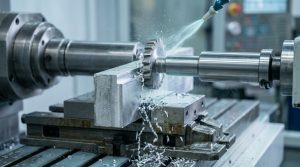
What Is Side Milling?
Side milling is a machining process that removes material using the peripheral edges of a rotating cutter rather than its end face. The cutter engages the side of the workpiece, producing vertical walls, slots, shoulders and grooves. The process gets its name from where the cutting happens. A face mill removes material with the bottom of the tool, while a side mill uses the teeth arranged around its circumference.
This difference in geometry changes how force is applied to the workpiece during the side milling process, and it shapes what the process is good at and where it falls short. Engineers reach for side milling when a part needs straight, vertical edges, or when a feature sits below the reach of a face mill. Keyways, mounting faces, structural brackets and mould bases are common candidates.
The cutter can be a dedicated side milling cutter mounted on an arbor, or an end mill held in a vertical spindle, depending on the machine and the geometry involved. Aria works with side milling regularly across aluminium, steel and stainless steel parts, and the process suits both prototype runs and higher volume production of high quality parts.
How Does the Side Milling Process Work?
Removing Material with the Cutter’s Side
The cutting action happens along the periphery of the tool. As the cutter rotates, each tooth takes a small bite of material and clears it as a chip. The workpiece moves against the cutter, or the cutter moves across the workpiece, depending on the layout of the side milling machines involved.
This radial engagement means the cutting force pushes sideways against the tool rather than downward. On a rigid setup this is not a problem. On a long, thin tool or a poorly clamped workpiece, the force can cause the tool to flex, and the wall then comes out tapered rather than straight.
Cutting Tool-to-Surface Orientation
The cutter sits parallel to the surface it is cutting, with its axis running along the length of the feature. This orientation is what separates side milling from face milling, where the tool axis points straight down into the surface.
Getting the orientation right matters for high accuracy. If the cutter axis is not properly aligned with the intended wall, the resulting surface will not be square, and any mating part will not fit as designed once that squareness is lost.
Step-by-Step Material Removal Process
Most side milling machining operations run through three stages:
- Roughing: removes the bulk of the material quickly, leaving a small allowance on the wall for later passes.
- Semi-finishing: corrects errors from the roughing stage, brings the surface closer to final size, and stabilises the cutting conditions.
- Finishing: takes a light cut at low radial engagement, delivering precise material removal for the final dimension, straightness and surface finish.
Skipping straight to a finishing pass on a rough surface usually causes chatter and inconsistent results, because the tool is trying to remove too much material with too little stability. Roughing, semi-finishing and finishing each handle a different part of the milling operation, and working through them in order keeps cutting forces manageable.
Types of Side Milling Cutters and Cutting Tools
Straight-Tooth Cutters for Flat, Even Surfaces
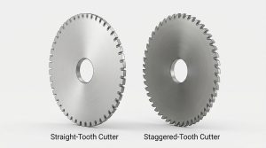
Each straight-tooth cutter, sometimes called a plain milling cutter, features cutting edges spaced evenly around the tool. They cut with a steady, uniform force, which suits flat vertical surfaces where a clean, consistent finish matters more than aggressive material removal.
These cutters work well in general-purpose milling. They perform particularly well on softer materials like aluminium, where cutting forces stay moderate throughout the pass.
Why Staggered Teeth Cut Down on Chatter
Staggered tooth cutters have teeth set at alternating angles along the tool body. This uneven spacing breaks up the rhythm of the cutting forces, and that broken rhythm is what causes chatter in the first place. Each tooth engages the material slightly differently from the one before it, so vibration does not build up into a repeating pattern.
This design suits deeper cuts, complex grooves and tougher materials, where a straight-tooth cutter would struggle with the heat buildup and vibration these jobs generate. Staggered cutters also tend to deliver longer tool life under heavy loads, since the cutting force is spread more evenly across the tool.
How to Choose the Right Cutting Tool by Cutter Width and Type
Choosing the right tool comes down to matching it to the feature and the material. Cutter width should match the slot or wall width closely when selecting milling cutters for the job, since the wrong choice on the same job means an oversized cutter wastes time in extra passes, and an undersized one leaves stock that needs a second operation to clear.
| Requirement | Recommended Cutter |
| Flat vertical wall, light cut | Straight-tooth cutter |
| Wide slot, heavy stock removal | Staggered-tooth cutter |
| Deep slot with tight tolerance | Narrow staggered cutter, multiple passes |
| Internal pocket or complex profile | End mill rather than side milling cutter |
An end mill and a side milling cutter are not always interchangeable. A side milling cutter, mounted on an arbor with support at both ends, holds up better under heavy radial load and long, deep cuts. An end mill offers more flexibility for pockets, contours and features that a side milling cutter cannot reach, but it is more prone to deflection under the same load because it is only supported at one end.
What Materials Can Be Side Milled?
Side milling works across a wide range of metals, plastics and composites, though the milling parameters change considerably from one material to the next. Aluminium machines easily at high speed and produces a good finish with minimal tool wear. Mild steel and other carbon steels need lower speeds and more attention to coolant, since heat builds up faster. Stainless steel work-hardens if the feed rate drops too low, so a consistent chip load matters more here than with softer metals.
Hard-to-Machine Materials
Titanium alloys and nickel-based superalloys present a harder challenge. These materials retain heat at the cutting edge rather than carrying it away in the chip, and this heat buildup shortens tool life quickly if speeds are not reduced. Carbide cutters with heat-resistant coatings, combined with high-pressure coolant, are usually needed for high precision work and to get acceptable cutter life on these materials.
Hardened steels above 45 HRC can also be side milled, though this usually means a lower feed, shallower depth of cut, and cutters designed specifically for hard milling.
Plastics and Composites
Plastics such as POM, nylon and PTFE respond well to side milling but need lower cutting speeds to avoid melting the material at the cutting edge. Sharp tools with good chip clearance matter more here than raw cutting speed.
Composites like carbon fibre laminates wear tools down quickly because of their abrasive fibres. Diamond-coated cutters are the usual choice for these materials, since standard carbide wears out far too fast to be economical.
Side Milling vs End Milling vs Face Milling vs Plain Milling
Each of these milling processes engages the workpiece differently, and each suits a different type of feature.
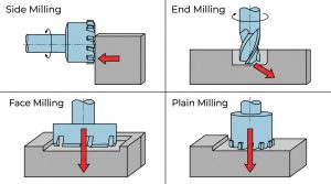
| Method | Cutting Area | Best For | Key Trait |
| Side Milling | Peripheral edge | Vertical walls, slots, shoulders | High rigidity on deep, narrow cuts |
| End Milling | Tip and periphery | Pockets, contours, 3D shapes | Flexible but more prone to deflection |
| Face Milling | Tool face | Flat surface finishing | Fast stock removal, planar accuracy |
| Plain Milling | Top face of cylindrical cutter | Wide, flat surfaces | Efficient for large flat areas |
Side milling and end milling both cut with the side of the tool, but the support behind the tool differs. A side milling cutter on an arbor is supported at both ends, so it resists deflection well even on deep cuts, while an end mill is held only at the spindle end, which limits how deep it can cut before deflection becomes a problem.
Face milling cutters and plain milling both work on the top face, producing flat plane surfaces rather than a side wall, which is why they cannot reach internal walls or vertical shoulders the way side milling can. Choosing between the four usually comes down to the geometry of the feature rather than personal preference.
Cutting Speed, Feed Rate, and Depth of Cut in Side Milling
Dialing In Cutting Speed Against Feed Rate
Cutting speed and feed rate, both part of the wider milling parameters, need to move together, not independently. Cutting speed controls how fast the tool edge moves through the material, set through the machine’s spindle speed, and it depends mainly on the material being cut. Aluminium tolerates high speeds, steel needs a moderate range, and titanium needs to run slow.
Feed rate determines how thick each chip is. A lower feed makes the tool rub rather than cut, generating heat and dulling the edge quickly. Too fast, and the load on each tooth becomes excessive, risking chipping or breakage. The right balance keeps the chip thick enough to carry heat away without overloading the cutter, which keeps cutting efficiency high.
How Depth of Cut Splits Between Radial and Axial
Depth of cut in side milling has two components. Radial depth controls how far the cutter reaches into the material sideways, and axial depth controls how much of the cutter length engages the workpiece vertically.
Radial depth has a much bigger effect on tool deflection than axial depth. A cutter engaging at 40 percent of its diameter radially will deflect far more than one engaging at 10 percent, even at the same axial depth. This is why roughing passes typically use heavier radial engagement, while finishing passes cut back to a light, shallow radial pass to correct any taper left behind.
Picking a Cutting Direction: Climb or Conventional
Climb milling feeds the cutter in the same direction the workpiece is moving. This pulls chips away from the cutting edge and generally gives a better finish, and it reduces rubbing at the start of each tooth’s engagement, which helps tool life too.
Conventional milling feeds the cutter against the direction of movement. It puts more resistance into the cut, which can help on machines with backlash in the table drive, since it keeps the cutter pressed against one side of the lead screw consistently.
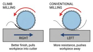
| Factor | Climb Milling | Conventional Milling |
| Surface finish | Generally better | Slightly rougher |
| Tool wear | Lower, less rubbing | Higher, more rubbing at entry |
| Machine suitability | Modern CNC with rigid drive | Older or less rigid setups |
| Common use | Finishing passes | Roughing, manual machines |
Coolant and Lubrication
Coolant does two jobs in this side milling operation. It carries away heat buildup from the cutting zone, and it helps flush chips clear of the slot or wall being cut. Flood coolant suits most steel and general machining work, while minimum quantity lubrication suits aluminium, where excess coolant can leave marks on the finished surface rather than improving the cut.
Deep slots need more coolant pressure than shallow ones, since chips have further to travel before they clear the cutting zone. Without enough pressure, metal chips get trapped and recut, which damages the surface finish and shortens tool life.
Applications of the Side Milling Operation on Flat Surfaces
Machining Square Shoulders and Straight Walls
This side milling operation produces square, accurate shoulders where two surfaces meet at a defined height. This comes up constantly in bracket and housing work, where a shoulder locates a mating part or defines a mounting face. The rigidity of the process, particularly with a properly supported cutter, keeps the wall straight along its full height rather than tapering near the bottom, a result that face milling cannot always deliver on a vertical wall.
Cutting Keyways, Slots, and Grooves
Keyways, T-slots and general grooves, often started with a plunge cutting move before the cutter feeds sideways, are one of the most common reasons to choose side milling over other processes. The cutter engages three surfaces at once inside a slot, the two side walls and the floor, so chip control and coolant delivery need more attention here than on an open wall. Slot width is controlled directly by cutter width, which makes cutter selection the first decision to get right before milling slots begins.
Contours and Steps
Side milling can also follow a contoured path rather than a straight line, producing stepped features or gentle curves along an edge. This suits mould cavities, gear blanks and parts with complex geometries where a single straight wall will not do the job.
Industry Use Cases
Aerospace manufacturers use side milling for structural brackets and turbine components, where high precision and clean edges matter for both fit and fatigue performance. Gear manufacturing relies on milling slots, keyways and tooth profiles accurately. Mould and die shops use it to form cavity walls and guide slots that need to hold tight tolerances over the life of the tool.
Advantages of Side Milling
Side milling earns its place in a machining plan for a handful of clear reasons. Most of them come down to how the cutter engages the material and how well that geometry resists the forces working against it.
Tight tolerances on vertical features: the cutter geometry resists deflection better than a single-point tool, particularly when the cutter is properly supported. Walls and slots stay straight along their full height rather than tapering.
Wide material range: the process handles soft aluminium through to hardened steels and titanium, given the right tool geometry and parameters. Few other milling processes cover that same range without swapping machines.
Good surface finish: the peripheral cutting action leaves a consistent texture along the wall. This often removes the need for a separate polishing step that face milling sometimes requires.
Scales from prototypes to volume production: a simple single-cutter setup keeps small batches economical. Straddle milling and gang milling scale the same process up once volumes justify the extra tooling.
Cutter variety adds flexibility: plain, staggered, angular and interlocking cutters each suit a different job. Switching cutter type adapts the process to a new feature without switching to a different machine.
Efficient on wide or deep features: a wide cutter clears more material per pass than a narrow end mill working the same wall. This shortens cycle time on long, straight features.
Disadvantage of Side Milling
Side milling also carries limitations that shape when it makes sense to use this machining process. Most of them trace back to the same radial cutting force that gives the process its strengths.
Poor fit for internal pockets: the cutter needs a clear path to reach the feature from the side. Deep cavities and enclosed pockets usually call for end milling instead.
Risk to thin workpieces: the lateral cutting force can bend or deform thin walls before the cut is complete. Extra support or a lighter pass is often needed to avoid this.
Longer setup and programming time: multiple cutters, arbor spacers and staged passes all add time compared with a simple face milling operation. This matters most on short production runs.
Higher tool wear: the peripheral edges take continuous load rather than sharing it across a broader face. Tool replacement tends to come round faster than on comparable face milling jobs.
Sensitive to rigidity: long tool overhang or a weak workholding setup shows up quickly as chatter or a tapered wall. The process rewards a stable setup more than some other milling processes do.
Limited to side-accessible features: any geometry that blocks a clear side approach rules side milling out. Complex 3D shapes and undercuts usually need a different process entirely.
Side Milling Problems and How to Fix Chip Evacuation Issues
Spotting and Fixing Chatter Marks
Chatter shows up as a repeating pattern of marks along the wall, usually caused by the tool and workpiece vibrating together at a natural frequency. Long tool overhang, high radial engagement, incorrect spindle speed and a loose workpiece clamp are the usual culprits.
Shortening the tool holder, reducing radial engagement, and checking that the workpiece is properly secured will resolve most chatter problems. Switching to a staggered-tooth cutter also helps, since it breaks up the regular pattern that drives chatter.
Cutting Tool Wear
Tool wear accelerates when cutting speed runs too high, when coolant flow is inadequate, or when tool geometry does not suit the workpiece. High-speed steel wears faster than carbide on most jobs, and uncoated carbide wears faster than coated carbide on abrasive or high-temperature materials.
Matching tool material and coating to the workpiece extends tool life and avoids poor surface finish. Keeping cutting speed within the recommended range and inspecting the tool regularly catches wear before it affects part quality.
When Thin Parts Bend Under the Cut
Thin walls and delicate features bend under the lateral force of side milling, which throws off the final dimension once the part is released from its fixture. The problem shows up most often on aluminium brackets and sheet metal components.
Adding support ribs or backing material during machining helps control this. Reducing radial engagement and using climb milling to pull the part into the fixture, rather than away from it, also reduces the effect. In some cases, switching to multiple light finishing passes instead of one heavier cut solves the problem entirely.
Clearing Chips Before They Get Recut
Poor chip evacuation lets metal chips stay trapped in a slot, where they get run over again by the cutter, generating extra heat and leaving marks on the surface. The problem is more common in deep, narrow slots than on open walls.
Higher coolant pressure and cutters with better chip-breaking geometry both support proper chip removal. Trochoidal toolpaths that keep the cut open for chips to escape also help, and on very deep slots, air blast alongside coolant clears chips that coolant alone cannot flush out.
FAQs
How Do You Pick the Right Cutter Diameter for a Slot?
Match the cutter diameter as closely as possible to the finished slot width. A cutter that is too narrow needs a second pass to open the slot to size, and a cutter that is too wide cannot produce the slot at all. Leave a small finishing allowance if tight tolerances are needed, and take the final pass at a lighter radial engagement.
What Tolerances Can You Realistically Hold with Side Milling?
Well set up side milling typically holds tolerances between plus or minus 0.02 and 0.05 millimetres on finishing passes, depending on machine rigidity, tool condition and material. Tighter tolerances are achievable with a rigid setup, a sharp tool and a light finishing pass, but they usually mean slower cycle times.
How Long Should a Side Milling Cutter Last Before Replacement?
Cutter life depends heavily on material and cutting parameters, so there is no single number that applies everywhere. Carbide cutters on steel typically last considerably longer than high-speed steel cutters under the same conditions. Watching for a decline in surface finish or an increase in cutting sound is usually a better guide than a fixed replacement schedule.
Can Side Milling Handle Angled or Curved Edges?
Yes. Angular cutters ground to a specific angle produce chamfers and tapered edges, and a cutter following a curved toolpath can machine contoured profiles. The tool still needs a clear side approach to the feature, so very tight internal curves may suit an end mill better than a dedicated side milling cutter.
Does Side Milling Work for Small Batches, or Only High-Volume Runs?
Side milling suits both. Setup time is the main cost driver on small batches, so a simple single-cutter setup keeps prototype work economical. Straddle milling and gang milling, which use multiple cutters on one arbor, become worthwhile once volumes rise high enough to justify the extra setup time.
What’s Driving Up the Cost of a Side Milling Job?
Deep features that need multiple passes, tight tolerances that demand slower feeds and extra inspection, and difficult materials that wear tools quickly all push cost up. Long tool overhang and thin walls also add cost indirectly, since they usually mean slower cutting parameters to control deflection and deformation.
What Causes Uneven or Tapered Walls During Side Milling?
Tool deflection under radial load is the most common cause. A long, thin tool bends slightly under cutting force, and this bend shows up as a taper along the wall height. Weak workholding and excessive radial engagement make the problem worse, and reducing radial engagement and shortening tool overhang usually correct it.
When Does End Milling Outperform Side Milling on Precision?
End milling tends to do better on complex 3D profiles and internal pockets, where a side milling cutter simply cannot reach. For a straightforward deep slot or a long straight wall, a properly supported side milling cutter usually holds better accuracy than an end mill of similar diameter, since it resists deflection more effectively.
Where Does Thread Milling Fit Compared to Side Milling?
Thread milling is a separate operation aimed specifically at cutting internal or external threads, using a helical toolpath. Side milling is not suited to thread forms at all, and the two are chosen for entirely different features rather than being alternatives to each other.
Can Side Milling Run Unattended on a CNC Setup?
Side milling runs well unattended in CNC machining once the programme and tooling are proven on a modern milling machine, particularly for repeat production parts. Deep slots and thin-walled parts still benefit from an operator checking the first few parts, since chip evacuation and deflection issues are easier to catch early than after a full unattended batch.
When Would You Choose Saw Milling Over Side Milling?
Saw milling suits narrow, deep cuts made with a thin slitting saw, particularly when parting a workpiece into sections or cutting very narrow slots where a standard side milling cutter would remove too much material. As a closing conclusion side milling remains the better choice for wider slots, shoulders and vertical walls where the extra width of a standard cutter is not a problem.
