

 EU
EUSlot milling is one of the most common operations in a machine shop. It shows up in keyways, T-slots, mounting channels, and hundreds of other features across metal and plastic parts.
It looks simple on the surface. A cutter moves along a line and removes a strip of material. In practice, the process involves real engineering choices around tool selection, depth control, and heat management.
Get those choices wrong and a slot job turns into broken tools, poor surface finish, or scrapped parts. This guide walks through what slot milling is, how it works step by step, the cutters used for it, and the problems that come up most often on the shop floor.
1. What is Slot Milling
Slot milling is a machining process that cuts a groove or channel into a workpiece using a rotating cutter, typically an end mill. The cutter engages the material from two or more sides at once, unlike face milling, which cuts a flat top surface, or an operation that only contours an edge. This is what separates slotting from simple profiling work.
Slots serve many purposes in mechanical design. A keyway slot locks a shaft to a hub. A T-slot on a machine table holds fixtures in place. A channel in a housing routes a cable or seats a gasket.
Whatever the function, the slot geometry stays the same at its core: two parallel walls and a floor, cut to a set slot width, slot depth, and length.
Creating slots this way covers a range of approaches. A slot might be cut in a single pass with an end mill sized to match the slot width, or it might be roughed out with a smaller tool and finished with a sizing pass. The right method depends on the slot dimensions, the material, and the tolerance the design calls for.
2. How Slot Milling Works
The slot milling process runs through a fairly consistent sequence, regardless of the machine or cutter involved. Each stage affects the next, so a mistake early on tends to show up as a defect later.
Fixturing and Setup
The workpiece needs to be held rigidly before any cutting starts. Slot milling puts more sideways load on a part than many other operations, because the cutter is engaged on two walls rather than one.
A part that shifts or vibrates in the vise will produce a slot that tapers, wanders, or comes out oversized. Clamping close to the cut area, using soft jaws on delicate parts, and checking for part flex under load all help maintain accuracy throughout the cut.
Tool Entry Method
The cutter has to get into the material somehow. For an open slot, the tool can enter from the side or the end, moving straight into position before the cutting pass begins.
For a closed or blind slot, the cutter often needs to plunge straight down into solid material first. Plunging puts heavy axial load on the tool tip, so machinists commonly control the ramp angle with a ramping or helical entry instead, where the tool spirals or angles down gradually rather than dropping straight in.
Bulk Material Removal
Once the tool is positioned, the main material removal pass begins. For narrow or shallow slots, this rough slotting stage might be a single full-width pass.
For wider or deeper slots, the programmer often breaks the cut into multiple passes for controlled chip removal, keeping cutting forces and heat within reasonable limits. Trochoidal milling, covered later in this guide, is a common way to manage this stage on tougher materials.
Final Sizing Pass
After roughing, a lighter finishing pass brings the slot to its final width, depth, and surface finish. This pass typically removes a small, consistent amount of stock on each wall.
It corrects for any residual tool deflection or inconsistency from the roughing stage and gives a cleaner wall surface.
Inspection and Cleanup
The last stage checks the slot against the drawing. Width, depth, straightness, and surface finish all get measured, often with calipers, height gauges, or a CMM for tighter tolerances.
Deburring follows, since slot edges are prone to burr formation that needs to be removed before the part moves on to assembly or the next machining operation.
3. Types of Slot Milling Cutters
Different slot shapes call for different milling cutters. Getting tool selection wrong is one of the more common reasons a slotting job goes wrong before it even starts.
End Mill
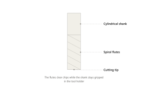
The end mill is the default choice for general slotting work. It cuts on its face and its sides, which lets it plunge into material and move sideways in the same pass.
The flute geometry, typically two flutes for slotting, clears chips well, though four-flute versions are used where finish quality matters more than chip clearance. Long edge cutters extend reach for deeper slots but need more careful feed control.
End mills work well for slot widths that match standard cutter diameters and tool diameters, and for slots that need moderate depth. Matching flute geometry and coating to the job also gives longer tool life.
Side Milling Cutter
A side milling cutter, sometimes called a side and face cutter, has teeth on its outer diameter and on one or both faces. It is mounted on an arbor rather than held in a standard tool holder, and arbor support keeps it rigid as it cuts a slot by feeding along the workpiece with the cutter’s circumference doing the work.
This style suits wider slots and heavier stock removal, particularly on manual mills and horizontal milling machines.
T-Slot Cutter
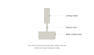
A T-slot cutter has a narrow neck below a wider cutting head, shaped to cut the undercut portion of a T-slot after a straight slot has already been machined. T-slots are used on machine tables and fixtures to accommodate fasteners such as T-bolts, which slide along screw tracks machined into the slot.
It is a two-step process: a standard end mill or side cutter forms the vertical slot first, and the T-slot cutter follows to open up the sides underneath.
Woodruff Key Cutter
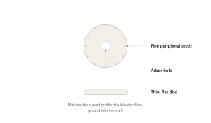
This cutter is shaped to produce the semicircular keyway used with Woodruff keys, common on shafts in smaller mechanical assemblies.
The cutter’s profile matches the curved key shape directly, so no separate finishing operation is needed for the keyway’s curved floor.
Gang Milling Cutter
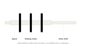
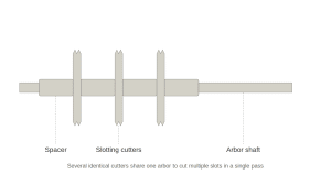
Gang milling uses several cutters mounted together on one arbor, spaced to cut multiple parallel slots or a complex profile in a single pass.
It is a production technique, useful when the same slot pattern needs to be repeated across many identical parts, since it cuts several features at once instead of one at a time.
Closed Slots and Matching Tools
Closed slots, meaning slots that do not run out to the edge of the part, generally need a cutter capable of plunging, such as a centre-cutting end mill. They are common in internal grooving applications where radial depth control matters, since a side milling cutter cannot start a closed slot on its own because it cuts from the side, not from the tip.
Matching the tool to the slot type, open or closed, at the design stage avoids reworking the toolpath later.
4. Slot Milling vs. Side Milling vs. End Milling
All three methods fall under general slot cutting work, distinguished mainly by how the cutter engages the material.
| Aspect | Slot Milling | Side Milling | End Milling |
| Cutting engagement | Both walls engaged at once | One wall engaged at a time | Face or side, depending on pass |
| Typical tool | End mill or side cutter | Side and face cutter | End mill |
| Common use | Keyways, channels, T-slots | Shoulder cuts, wide grooves | Profiling, pocketing, contouring |
| Tool load | Higher, two-sided contact | Moderate, one-sided contact | Varies by pass type |
| Best suited for | Fixed-width grooves | Wider or deeper single-wall cuts | General shaping and finishing |
The overlap between these methods is real. An end mill can perform slot milling, side milling, or general profiling depending on how it is programmed.
The distinction lies in the cutting engagement and the resulting geometry, not in the milling cutter itself.
5. Slot Milling Applications by Industry
The table below lists specific slot milling applications by industry.
| Industry | Typical Slot Application |
| Automotive | Keyways on shafts, mounting slots in brackets and housings, plus slots in brake rotors, gear blanks, and engine blocks |
| Aerospace | Weight-reduction channels, wiring raceways, structural slots |
| Medical devices | Precision slots in surgical instrument components |
| Industrial machinery | T-slots for fixture mounting, adjustment channels, gang milling for repeated slot patterns |
| Electronics enclosures | Cable routing slots, cooling vents, precision slots in semiconductor wafers and carrier trays |
| Consumer products | Slide mechanisms, assembly alignment grooves |
Across these industries, the underlying requirement stays consistent: a slot that holds its dimension and finish under the load or fit it was designed for.
6. Slot Milling Toolpaths
Different slot milling techniques control how the cutter engages the material during slot cutting, which affects heat, tool wear, and finish.
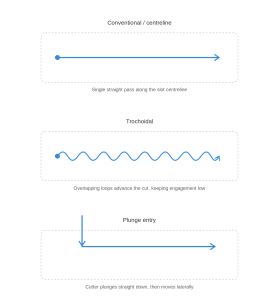
Conventional / Centerline Slotting
This is the straightforward approach: the cutter moves along the centreline of the slot at full width, following the slot axis in a single pass.
It works well for narrow and shallow slots in easy-to-machine materials, where tool load and heat stay manageable without special toolpath strategies.
Trochoidal Milling
Trochoidal milling moves the cutter in a series of overlapping loops rather than a straight line, maintaining controlled radial engagement at any given moment even while cutting a full-width slot. Advanced CAM software generates these loop paths automatically, adjusting the loop radius to the material and cutter.
This reduces heat buildup and tool wear while giving better chip evacuation through the loops, which makes it a common choice for harder materials or deeper slots where a straight pass would overload the tool.
Plunging
Plunging drives the cutter straight down into the material, used mainly to start a closed slot or to rough out material quickly in a controlled area.
It puts significant load on the tool tip, so plunge rates are usually kept conservative compared with lateral feed rates.
Entry and Setup Practices
Ramping and helical entry moves, mentioned earlier under tool entry, belong here as well. They reduce the shock load that a straight plunge creates.
They are standard practice on CNC programs for anything beyond a shallow slot.
7. Advantages of Slot Milling
Slot milling remains popular for a reason. It holds up well across materials, shapes, and production volumes.
High precision: Slot milling produces accurate, repeatable slots across a wide range of materials, from aluminium and mild steel to plastics and harder alloys.
Versatile slot shapes: Straight slots, T-slots, curved keyways, and stepped channels can all be produced with the right cutter and toolpath, without switching to an entirely different machining method.
Wide material compatibility: The process handles soft metals such as aluminium, along with mild steel, softer plastics, and harder alloys, with tool and speed choices adjusted for each.
Cost-effective vs. broaching/EDM: It is generally faster to set up and cheaper for low to medium production volumes, since it does not require a dedicated broach tool or wire EDM setup time.
Good surface finish: Surface finish on the slot walls is generally good straight off the finishing pass, particularly when corner radius and edge sharpness are matched to the material.
Scales to production: The process works as well for a single prototype as it does for a long production run, using gang milling to cut several features in one pass when volumes call for it.
8. Disadvantages of Slot Milling
The two-sided engagement that makes slot milling effective also makes it demanding on the tool and machine.
Vibration-prone: Long tool overhangs or poorly clamped parts often lead to chatter, which shows up as visible marks on the slot walls.
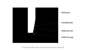
Tool deflection risk: As the cutter pushes into the material from two sides, cutting forces build up and can bend it slightly off its programmed path, leaving a slot that is not perfectly straight or consistent in width.
Poor chip evacuation: Chips have less room to escape inside a slot than in an open cut, leading to chip packing that generates extra heat and can scar the finished surface.
Heat buildup: Heat is a persistent concern in slotting, especially in deep slots where the cutter stays engaged in the cut for longer stretches.
Deep slots are harder to control: A high depth-to-diameter ratio increases the risk of tool overload, deflection, and breakage, so deep slots need more careful toolpath planning.
Higher tooling cost: Specialised cutters such as T-slot cutters or Woodruff key cutters are single-purpose tools, which pushes tooling costs above simpler operations.
9. How to Choose the Right Cutter and Approach
Getting tool selection right for a slot milling operation depends on matching cutter, material, and toolpath to the job.
Material Compatibility
The workpiece material sets the boundaries for slot cutting tool choice. Aluminium, soft metals, and softer plastics allow higher spindle speeds and more aggressive feeds, and they tolerate uncoated or lightly coated carbide tools well.
Steels and harder alloys need tougher tool coatings, lower feeds, and often trochoidal milling to manage heat. Matching the tool material, coating, and geometry to the workpiece reduces wear and gives longer tool life considerably.
Key Cutting Edge Parameters
Flute count, helix angle, and the geometry of the cutting edges all affect how a slot cuts. Fewer flutes clear chips more easily, which helps in deep and narrow slots where trapped chips are a risk.
A higher helix angle generally gives a smoother cut and better chip evacuation but can reduce rigidity slightly. Cutter diameter and tool diameter need to match the slot width closely when a single-pass approach is used, since an undersized cutter run at full width for a slightly wider slot leads to uneven wall finish.
Corner radius, edge length, and overall tool stability also matter. A larger corner radius adds strength at the cutting edge, a longer reach lets the tool cut deeper in one setup, and feed rate combined with flute count sets the chip thickness per tooth, which needs to stay within the tool manufacturer’s range to avoid rubbing or overloading the edge.
Depth-to-Diameter Ratio and Tooling Strategy
Machining deep slots, where slot depth runs well beyond the cutter diameter, needs a different strategy than a shallow one. As a rough guide, once slot depth exceeds around three to four times the cutter or tool diameter, tool overload, deflection, and chip evacuation problems increase sharply.
At that point, breaking the cut into multiple depth passes, switching to trochoidal milling, or choosing a shorter, stiffer tool with an extended reach only where needed all help keep the process under control and preserve tool stability. These slot milling techniques apply equally to deep slots in tough alloys and to narrow and shallow slots where rigidity is still limited by tool diameter.
10. Slot Milling Problems and Fixes
The slot milling process runs into a handful of recurring problems, most tied to chip control, heat, or tool rigidity.
Trapped Chip Damage
Chips that cannot escape the slot get re-cut by the tool or dragged along the wall, leaving scratches and accelerating tool wear. This is more common in deep and narrow slots and in materials prone to poor chip formation.
Increasing coolant flow, sometimes using high pressure coolant or compressed air directed into the slot, reducing radial engagement through trochoidal milling, and using a milling cutter geometry designed for better chip flow all help clear this problem.
Thermal Buildup
Heat concentrates quickly in a slot because the cutter stays in continuous contact with the material on two sides. Left unmanaged, this softens the tool edge, discolours the workpiece, and can cause dimensional drift as the part expands slightly during cutting.
Adequate coolant flow, lower cutting speeds in harder materials, and toolpaths that reduce continuous engagement time are the standard fixes.
Cutter Deflection
A long, thin cutter pushed hard from two sides will bend slightly under radial forces, and that bend shows up as a slot that is narrower at the bottom than at the top, or one that drifts off its intended line.
Shortening the tool’s stick-out length, choosing a larger diameter cutter where the design allows it, and slowing the feed rate in the final pass all reduce deflection.
A separate finishing pass at light depth, cut after roughing, corrects most of the residual tool deflection left over from roughing.
11. FAQ
Can I Use an End Mill to Do Slot Milling?
Yes. The end mill is the most common tool used for slot milling, since it can plunge and cut on its sides in the same setup, unlike face milling cutters, which are built mainly for flat surface work.
The main requirement is choosing a diameter and flute count suited to the slot width and material.
Can Slot Milling Be Done on Plastic Parts?
Yes, and it is a routine operation on plastics. The main adjustments compared with metal are higher spindle speeds, sharper cutting edges to avoid melting the material at the cut edge, and careful chip evacuation.
Plastic chips can gum up around the tool if heat builds up.
Is Slot Milling Suitable for Tight Tolerances?
Slot milling can hold tight tolerances when the process includes a separate finishing pass, rigid fixturing, and a cutter matched closely to the required width.
Single-pass slotting at full engagement tends to hold looser tolerances than a rough-then-finish approach.
Why Does Slot Milling Generate More Heat Than Other Milling Methods?
The cutter is engaged with the workpiece on two sides at once rather than one, which increases the contact area and the friction generated per pass.
Combined with restricted chip clearance inside a narrow slot, this raises the overall heat generated compared with an open profiling cut of similar depth.
