

 EU
EUA broken tap inside a finished part is one of the worst failures in a machine shop. Thread milling avoids that risk, using a smaller rotating cutter instead of a tool that matches the thread size exactly.
This guide covers what thread milling is, how it works, the types of tools available, and how it compares with tapping. It is written for mechanical engineers, product designers, and procurement managers deciding whether thread milling suits a part with hard materials, tight tolerances, or a blind hole.
What Is Thread Milling?
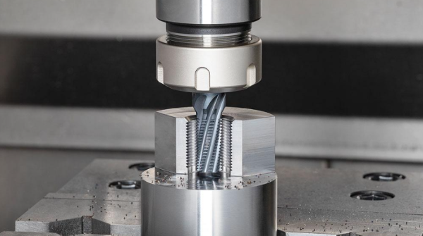
Thread milling is a CNC machining process used to produce internal or external threads of various sizes and pitches. A rotating cutting tool follows a three axis helical interpolation path, with the X, Y, and Z axes combining in simultaneous movement. Unlike tapping, where the tool diameter matches the thread size directly, a thread milling cutter is significantly smaller than the feature being threaded.
Every thread has three diameters that matter for setup. The major diameter sits at the outer crest, the pitch diameter runs through the middle of the flank, and the minor diameter sits at the root. Thread milling can hit all three within tolerance by adjusting the CNC wear offset, which is what makes fit adjustment possible without changing tools. The same thread mill can also cut custom threads and standard threads alike, whether the job calls for external threads on a stud or internal threads inside a hole, provided the pitch stays the same.
Thread milling covers most common thread standards. ISO metric threads use a 60 degree profile for general purpose work, and Unified National Coarse threads serve a similar role in North America. ACME and buttress profiles come up less often but are still millable. ACME threads suit lead screws and power screws, while buttress threads handle high axial thrust in one direction. The same helical interpolation principle applies to each; only the tool profile and the program change.
Advantages
- Tool flexibility: a single tool can machine internal and external threads, right hand and left hand threads, and a range of diameters, provided they share the same pitch. A shop can cover more thread sizes with fewer tools in the rack.
- Thread quality: tight pitch tolerances are achieved through CNC wear offset adjustments, so thread fit can be corrected without swapping tools. High spindle speeds also give a cleaner surface finish on the flanks.
- Low scrap risk: because the cutter is smaller than the hole, a broken tool does not lock into the part. It can be removed easily, without ruining a high value component the way a snapped tap often does.
- Chip evacuation: the process produces short, manageable chips that flush out easily with coolant or an air blast. This avoids the clogging that taps can cause in blind or deep holes.
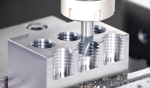
- Blind hole capability: thread milling cuts a full thread profile right to the bottom of a blind hole. Tapping needs extra depth clearance for the tap’s chamfered entry teeth, which this process does not require. This is a clear advantage in blind holes, where a broken tap creates the highest risk of scrapping the part.
- Hard material machining: cutting forces are much lower than tapping, so thread milling works reliably in hardened steels up to 62 HRC, titanium, Inconel, and thin walled parts that would distort under a tap. Lower cutting forces also mean improved tool life, since the cutter is not subjected to the high torque a tap needs to push through hardened material.
Disadvantages
- Slower in small holes: for standard small diameter holes in soft materials, high speed rigid tapping is usually faster. Thread milling adds cycle time that is hard to justify on easy jobs.
- Equipment demands: the process needs three axis simultaneous helical interpolation, using G02 or G03 with Z movement. Manual mills and basic CNC controls without this capability cannot perform the required interpolation.
- Higher tooling and software costs: solid carbide and indexable thread mills carry a higher upfront cost than standard taps, and CAM software for generating the toolpath adds to the investment.
- Deflection in deep holes: in holes deeper than roughly three times the diameter, long tool overhang can cause vibration or deflection. This often calls for multi pass strategies or a specialised toolpath.
How Does Thread Milling Work?
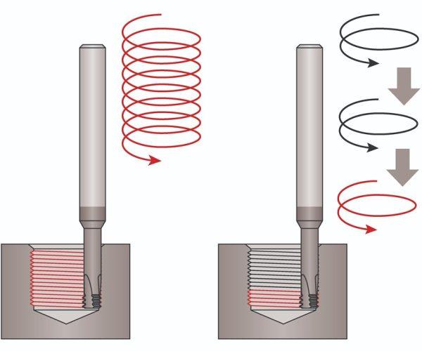
Thread milling runs on three axis helical interpolation, combining a circular path in the X-Y plane with a steady linear advance along Z.
The tool first enters the pre-drilled hole, or moves alongside the stud for external threads, and travels down to the required start depth. No cutting happens at this stage.
It then executes an arc entry, sometimes called an arc in move, sweeping into the workpiece along a smooth, tangential path rather than a straight line plunge. This keeps engagement force low and prevents chatter as the cut begins.
The spindle then rotates at high speed while the tool follows a full 360 degree circular path in X and Y, tracing a tool path that repeats once for every revolution. At the same time, it advances along Z by exactly one thread pitch per revolution, so crest cutting and thread form are completed together in the same pass.
Once the tool reaches the required depth, it arcs out smoothly along the same tangential path used on entry, without touching the finished profile, then retracts along Z. This keeps the last thread crest clean and avoids marking the surface on the way out.
What Are the Types of Thread Milling Tools?
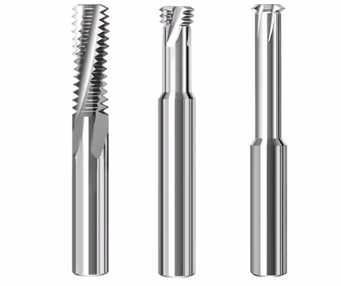
Thread mills vary by construction and by tooth profile. The right choice depends on hole size, thread depth, material hardness, and how many parts are running through the job.
By Profile Style
Single-Form Thread Mills
These carry one tooth profile and cut a single pitch of thread per revolution. Cutting forces stay minimal, so this type suits deep holes, tough alloys, and custom or non-standard threads where flexibility matters more than speed.
Multi-Form Thread Mills
These carry several rows of teeth along the cutting edge, so the tool completes the full thread depth in a single 360 degree revolution instead of stepping down over several passes. This cuts cycle time considerably, though the tool is restricted to one specific thread pitch rather than a range, since the profile height between rows is fixed to that pitch.
Full-Profile Thread Mills
These form the complete thread profile, crest included, in that same single pass. Because the crest comes out finished rather than left sharp or burred, there is no separate deburring step needed before the part moves on, which matters on parts that get handled by hand or mate against a seal.
Staggered Tooth Thread Mills
These stagger the teeth around the cutting edge instead of lining them up in the same plane, splitting the chip load between teeth. They cut both internal and external threads, and the staggered pattern breaks long chips into shorter sections, which helps in materials that would otherwise produce stringy, hard to clear chips.
By Tool Construction
Solid Carbide Thread Mills
These are machined from a single piece of carbide, which gives them high rigidity and precision. They are widely used for smaller holes, under roughly 15 mm (around 5/8 inch), and for work in hardened materials up to about 62 HRC , where accuracy matters most.
Indexable Thread Mills
These use a steel body fitted with replaceable carbide inserts. Only the insert wears out and needs replacing, not the whole tool, which makes this type cost effective for medium to large thread diameters, typically 3/4 inch and up . A single holder can also often take inserts ground to different pitches, which cuts down on the number of separate tool holders a shop needs to stock for a range of thread sizes.
HSS Thread Mills
Cut from high speed steel or powder metal rather than carbide, these suit softer materials, less rigid machine setups, and interrupted cuts where a carbide edge would be more likely to chip. They cost less than carbide tools, though they wear faster and run at lower speeds.
Lead and pitch are not always the same thing. On a single start thread, lead equals pitch. On a multi-start thread, lead equals pitch multiplied by the number of starts, so the CNC program needs the correct lead value or the finished thread will not mesh with its mating part.
Thread mills come in both metric and imperial sizes, so a shop can match the tool to the print without converting units. For external threads on a stud or cylinder, check that the tool has clearance from any shoulder next to the threaded section, since the cutter needs room to swing through its full arc.
Thread Milling Vs Tapping
Thread milling and tapping both produce internal threads, but the way they cut, and what that means for tool life, part safety, and cycle time, differs in almost every respect. The table below sets out the main points of comparison.
| Aspect | Thread Milling | Tapping |
| Motion | Three axis helical interpolation, tool rotates while tracing X-Y circle and advancing in Z | Direct axial feed, rotation rigidly synced to pitch |
| Tool size vs. feature | Cutter noticeably smaller than the hole | Tap diameter matches the thread exactly |
| Versatility | One tool covers multiple diameters, pitches, and left/right hand threads at the same pitch | Fixed to one diameter, one pitch, one direction |
| Cycle speed | Moderate to slower, especially in small holes | Very fast, ideal for high volume in soft materials |
| Tool breakage risk | Low, broken tool does not lock in, safe to remove | High, broken tap binds tight, may need EDM removal or scrap the part |
| Blind holes | Cuts full thread to the bottom of the hole | Needs extra clearance for the tap’s chamfer teeth |
| Fit and tolerance | Adjustable via CNC wear offsets | Fixed by the tap’s ground geometry |
Standard fit classes give both processes a common reference. Metric internal threads often specify a class such as 6H, while imperial threads use classes like 2B or 3B. A thread mill can hit any of these classes on the same tool, since the pitch diameter achieved on the part is checked against a thread gauge or reference chart and corrected through the wear offset if it drifts outside the class.
Best Practices for Thread Milling Setup
Pre-Drill Hole Preparation
Drill the hole to the standard minor diameter for internal threads, or machine the outer pin diameter for external features. Make sure the hole depth allows for the full thread engagement length needed, especially in blind holes.
Tool Selection
Select the thread mill based on workpiece material, hole diameter, thread depth, and pitch. Choose between solid carbide and indexable designs, and decide whether a single form or multi form cutter suits the job. Most tool manufacturers publish speed and feed charts for their thread mills, and some provide setup videos for specific materials, which is a faster starting point than calculating every parameter from scratch.
Milling Strategy Determination
Climb milling is generally recommended, since it gives a better surface finish and longer tool life. The alternative, conventional milling, feeds the tool in a direction opposed to its rotation, which tends to increase chatter and wear the cutting edge faster. For a standard right hand internal thread with the spindle turning clockwise, climb milling usually means starting at the bottom of the hole and interpolating upward. Reversing the spindle direction or the arc direction changes which travel direction gives climb milling, so the setup needs careful checking against the actual machine configuration rather than assumed by default.
Feed Rate and Speed Calculation
Feed rate needs calculating at the tool centre point, not the cutting edge. For internal threading, the tool centre traces a smaller arc than the outer cutting edge, since the edge that engages the hole wall sits at a larger radius. This compensation is essential. Without it, the actual feed at the cutting edge runs higher than the programmed value, which raises the risk of chipped edges or heavy vibration. Getting this compensation right keeps the feed accurate through the helical path.
G-Code Programming
Set up circular interpolation using G02 or G03, combined with Z axis movement. Program a smooth tangential arc for both entry and exit to avoid leaving tool marks on the thread flanks.
Execution and Inspection
Run a test pass first. Check the pitch diameter and thread profile with thread plug gauges or an optical comparator, then fine tune the wear offsets in the machine control before starting the full production run. A go and no-go plug gauge is usually enough to confirm the pitch diameter falls inside its class, while an optical comparator or thread profile projector suits checking flank angle and crest form on more critical applications.
Thread milling gives control that tapping cannot match, particularly on hardened materials, tight tolerances, and blind holes where a broken tap would mean scrapping the part. The benefits are clearest on high value components, where the fit achieved and the finish on the flanks are worth the extra cycle time. Getting there reliably still depends on the right tool selection and a toolpath dialled in for the material and geometry at hand.
If you are specifying threaded features on a part that needs this level of control, Aria’s engineering team can help work through tool choice, feed and speed calculations, and CNC programming for your specific application.
-100x100.jpg)