

 EU

Every machined assembly depends on accurate sizing at mating interfaces. The size limits of the shaft and hole decide how the joint behaves. The parts can rotate freely, locate with high accuracy, or lock together. In engineering, these three outcomes are known as clearance, transition, and interference fits.
This guide covers the types of fits and their subtypes. It explains how fits and tolerances relate, details ISO 286 and ANSI B4.1 designation codes, and shows how to choose the right fit.
What Is an Engineering Fit?
An engineering fit describes how two mating parts, such as a shaft and a hole, relate to each other. A single shaft or hole has a tolerance, but not a fit. A fit only exists when the two tolerance zones are compared.
With the hole size fixed, a smaller shaft leaves a gap. A larger shaft must be pressed in. If their size ranges overlap, either can happen. These are the three types of fits: clearance, interference, and transition.
Why Engineering Fits Matter
Engineering fits decide how an assembly moves, how fast it wears, and how long it lasts, and because each material expands, deforms, and wears differently, fit choice and material choice go hand in hand.
Key Reasons Engineering Fits Matter
Controlled Motion: The fit decides whether components rotate or slide freely, hold an exact position, or stay locked together under load.
Wear and Failure Prevention: A fit that is too loose causes vibration, noise, and early wear, while one that is too tight causes high stress and cracking.
Safety and Reliability: A loose bearing seat or a slipping gear hub caused by a poor fit can stop a machine or put operators at risk.
Cost Control: Every step toward tighter tolerance grades adds machining, finishing, and inspection cost, so the best fit is the loosest one that still meets the function.
Manufacturability: Standard fits such as H7/g6 or H7/p6 let shops use standard reamers and gauges, and they keep parts that pass inspection on their own working correctly once assembled.
Fits and Tolerances
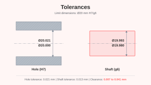
Tolerances and mechanical fits are related, but they describe different things. A tolerance sets how much a single feature, such as a hole or a shaft diameter, is allowed to vary from its nominal size. A fit describes the relationship created when the allowed sizes of two mating features are combined.
What Are Basic Size, Size Limits, and Tolerance Zones?
The basic size is the reference dimension used to set the limits and deviations of a part. The upper limit is the largest size the part may measure, and the lower limit is the smallest. The size tolerance is the difference between these two limits, and the band between them is the tolerance zone. For example, a Ø20 H7 hole has a lower limit of 20.000 mm and an upper limit of 20.021 mm, so its tolerance is 0.021 mm.
How Tolerance Affects Clearance
Clearance is the actual gap between mating features once they are assembled. Two parts that each stay within their own tolerance can still produce different clearances, depending on where their actual sizes fall within their tolerance zones.
For a Ø20 H7/g6 fit, the hole ranges from 20.000 to 20.021 mm and the shaft from 19.980 to 19.993 mm, so any acceptable pair can have a clearance from 0.007 to 0.041 mm.
Different Types of Engineering Fits
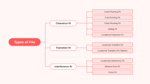
Clearance Fit
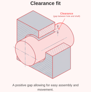
A clearance fit is a fit where the hole is always slightly larger than the shaft, leaving a gap between the two parts. Engineers choose a clearance fit when parts must move relative to each other, assemble easily, leave room for lubricant, allow for thermal expansion, or come apart repeatedly for service.
The whole shaft tolerance zone sits below the hole tolerance zone. The gap still varies from one assembly to the next, but even the tightest pair never ends up with interference.
Maximum and minimum clearance describe the loosest and tightest assembly possible within the specified tolerance range.
Maximum clearance = maximum hole size − minimum shaft size
Minimum clearance = minimum hole size − maximum shaft size
Clearance fits suit parts that need to slide, rotate, or assemble easily. Common applications include:
- Plain Bearings: The shaft turns inside a bushing on a thin oil film.
- Guide Shafts and Sliding Gears: The part moves along the shaft while keeping accurate alignment.
- Spindles and Sliding Rods: The clearance allows smooth, continuous motion with good accuracy.
- Linkages and Sliding Parts: The components can be inserted and removed with minimal force.
- Pivots and Latches: The joint swings freely even with dirt, heat, or slight misalignment.
Types of Clearance Fits
The five clearance fit subtypes below are listed from the loosest to the tightest.Loose running fits have the largest clearance among clearance fit subcategories.
| Fit Type | General Behavior | Typical Application | Hole Basis | Shaft Basis | ANSI Inch Class | Example (Ø20 mm) |
| Loose Running Fit | Largest clearance, allows for wide tolerances, dirt, and heat | Pivots, latches, and parts exposed to dust or corrosion | H11/c11 | C11/h11 | RC8–RC9 | 0.110 to 0.370 mm clearance |
| Free Running Fit | Generous clearance for high speeds, heavy journal loads, or large temperature changes | Shafts in plain bearings that rely on an oil film | H9/d9 | D9/h9 | RC7 | 0.065 to 0.169 mm clearance |
| Close Running Fit | Moderate clearance for accurate running at moderate speeds | Machine tools, sliding rods, and machine tool spindles | H8/f7 | F8/h7 | RC4 | 0.020 to 0.074 mm clearance |
| Sliding Fit | Small clearance for high accuracy; parts move and turn easily but are not meant to run freely | Guide shafts, sliding gears, slide valves, and clutch discs | H7/g6 | G7/h6 | LC5 | 0.007 to 0.041 mm clearance |
| Locational Clearance Fit | Minimal clearance, snug fit that still assembles by hand | Roller guides and shaft guides | H7/h6 | H7/h6 | LC2 | 0 to 0.034 mm clearance |
ANSI inch classes are the closest equivalents based on matching tolerance zones. Inch values differ slightly from the metric limits.
Transition Fit
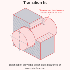
A transition fit sits between a clearance fit and an interference fit. Engineers use a transition fit when parts need accurate location with almost no play but must not be locked together permanently.
The hole and shaft tolerance zones overlap, so the size limits allow both a gap and an overlap. Depending on where the actual sizes fall, each pair ends up with a small clearance or a slight interference. This keeps play low without the strong grip of an interference fit.
A transition fit is fully described by two limits, its maximum clearance and its maximum interference, which together cover every possible assembly result.
Maximum clearance = maximum hole size − minimum shaft size
Maximum interference = maximum shaft size − minimum hole size
Transition fits suit assemblies that need both stability and easy removal, such as aerospace components and tooling fixtures. Common applications include:
- Tooling Fixtures: Locating components hold the workpiece in an exact position with minimal movement.
- Precision Assemblies: Engine and machinery components stay accurately aligned with almost no play.
- Bearing Seats: The bearing ring is held securely without creating excessive friction.
- Hubs, Gears, and Pulleys: The component is located accurately on the shaft but can still be removed.
- Driven Bushings and Armatures: The component is pressed onto the shaft with light force for more accurate location.
Types of Transition Fits
The two transition fit subtypes below are listed from the looser to the tighter.
| Fit Type | General Behavior | Typical Application | Hole Basis | Shaft Basis | ANSI Inch Class | Example (Ø20 mm) |
| Locational Transition Fit | Accurate location with either a small clearance or slight interference; assembles with a rubber mallet | Hubs, gears, pulleys, and bearings | H7/k6 | K7/h6 | LT3 | 0.019 mm clearance to 0.015 mm interference |
| Locational Transition Fit (Tighter) | More accurate location where greater interference is permissible; assembles with light force | Driven bushings and armatures on shafts | H7/n6 | N7/h6 | LT5 | 0.006 mm clearance to 0.028 mm interference |
ANSI inch classes are the closest equivalents based on matching tolerance zones. Inch values differ slightly from the metric limits.
Interference Fit
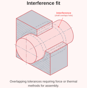
An interference fit, also known as a press fit or friction fit, is a fit where the shaft is always slightly larger than the hole. Engineers choose an interference fit when a joint must transmit torque without a keyed shaft, carry axial loads, resist vibration, or stay fixed for the life of the assembly.
Assembly needs mechanical force or heating and cooling to change the part sizes for a short time. After assembly, the shaft is slightly compressed and the hole slightly expands, creating contact pressure that holds the parts together. Too little interference gives weak holding force, while too much makes assembly difficult or damages the parts.
The minimum interference sets the loosest acceptable joint, while the maximum interference sets the tightest.
Maximum interference = maximum shaft size − minimum hole size
Minimum interference = minimum shaft size − maximum hole size
Interference fits suit parts that must not shift under load or vibration. Common applications include:
- Gears and Pulleys on Shafts: The hub is press fit onto the shaft so it cannot slip under load.
- Bearing Rings: The inner or outer ring is press fit in place so it cannot rotate or shift during operation.
- Bushings: The bushing is press fit into its housing and stays fixed while the shaft turns inside it.
- Hubs: The hub stays permanently mounted on the shaft and carries torque through friction alone.
Types of Interference Fits
The three interference fit subtypes below are listed from the lightest to the heaviest.
| Fit Type | General Behavior | Typical Application | Hole Basis | Shaft Basis | ANSI Inch Class | Example (Ø20 mm) |
| Locational Interference Fit | Light interference for rigid, accurate location without high bore pressure; assembles by cold pressing | Hubs, bushings, and bearings | H7/p6 | P7/h6 | LN2 | 0.001 to 0.035 mm interference |
| Medium Drive Fit | Moderate interference for ordinary steel parts; assembled by cold pressing or by shrink fitting on light sections, and the tightest fit usable with cast iron | Permanently mounted gears, shafts, and bushings | H7/s6 | S7/h6 | FN2 | 0.014 to 0.048 mm interference |
| Force Fit | Heavy interference for highly stressed parts; usually needs shrink fitting because press force is too high | Heavily loaded shafts and gears | H7/u6 | U7/h6 | FN4 | 0.020 to 0.054 mm interference |
ANSI inch classes are the closest equivalents based on matching tolerance zones. Inch values differ slightly from the metric limits. For basic sizes up to 3 mm, H7/p6 behaves as a transition fit.
Clearance vs Transition vs Interference Fit
| Factor | Clearance Fit | Transition Fit | Interference Fit |
| Size Relationship | Shaft stays smaller than the hole | Shaft and hole size ranges cross over | Shaft stays larger than the hole |
| Result After Assembly | A gap every time | Either a slight gap or a slight overlap | An overlap every time |
| How It Is Assembled | Normally pushed together by hand | By hand, with light taps, or with a light press | Requires force from a press, or thermal methods such as heating or cooling |
| Movement Between Parts | Allows free movement | Meant for accurate positioning, not continuous motion | Usually held still |
| Grip Strength | Low | Low to medium | Medium to high |
| Primary Use | Sliding, turning, and easy assembly | Precise positioning with almost no play | Firm retention or torque transmission |
| Typical Metric Fit (Hole Basis) | H7/g6 | H7/k6 | H7/p6 |
Actual clearance or interference depends on the nominal size.
The Hole and Shaft Basis System
Hole Basis System
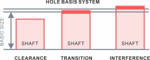
A hole basis system is a limits and fits method used in mechanical engineering in which the hole is held at the nominal size, with its lower deviation set to zero, and shaft sizes are changed to create the desired fit. It is the more common system in manufacturing because standard drills, reamers, broaches, and gauges make it easy to keep hole sizes standardized, while shaft sizes are easier to adjust by turning or grinding.
Shaft Basis System
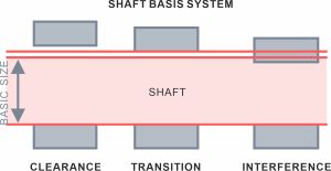
A shaft basis system is a limits and fits method used in mechanical engineering in which the shaft is held at the nominal size, with its upper deviation set to zero, so the nominal diameter is the largest allowed shaft size, and the hole size is changed to create different types of fits. It is used when the shaft size is already fixed or hard to machine further, so the required fit is set by changing the hole tolerance instead.
Engineering Standards for Fits: ISO and ANSI
ISO 286 Fit Codes
ISO 286 is the ISO system of limits and fits, published by the International Organization for Standardization. It uses an alpha numeric code, such as H7/g6, to describe how a hole and a shaft fit together. Each code has two parts that identify a particular fit and its tolerance, the tolerance class for the hole and the tolerance class for the shaft.
Capital Letter and Number (H7): Describes the hole, or internal feature.
Lowercase Letter and Number (g6): Describes the shaft, or external feature.
The Letter (Fundamental Deviation): Uppercase letters identify holes, lowercase letters identify shafts, and the letter sets the tolerance zone relative to the nominal size. In a hole basis system, the hole uses H, with a lower deviation of zero. In a shaft basis system, the shaft uses h, with an upper deviation of zero.
The Number (IT Grade): The number indicates the international tolerance grade and helps define acceptable size limits. A lower number means tighter tolerances and higher manufacturing costs.
ISO 286 fit codes cover three main types of fits:
Clearance Fits: Such as H11/c11 and H7/g6, where the parts slide or turn freely.
Transition Fits: Such as H7/k6 and H7/n6, where the parts locate accurately with very little play.
Interference Fits: Such as H7/p6 and H7/u6, where the parts are pressed or shrink fitted and stay locked together.
ANSI B4.1 Fit Classes
ANSI B4.1 is a US national standard titled Preferred Limits and Fits for Cylindrical Parts and published by ASME. It defines standard sizes, allowances, tolerances, and fit classes for plain, unthreaded cylindrical parts, with values given in thousandths of an inch. Its fit classes fall into three main groups.
Running and Sliding Fits (RC1 to RC9)
Each running and sliding fit is a clearance fit for parts that slide or rotate against each other.
RC1 to RC3: A close sliding fit, a sliding fit, and a precision running fit for accurate location or precise running at slow speeds.
RC4 to RC6: A close running fit (RC4) and medium running fits (RC5 to RC6) for accurate machinery, higher speeds, or heavy journal pressures.
RC7: A free running fit where accuracy is less important or large temperature changes occur.
RC8 to RC9: Loose running fits for wide commercial tolerances.
Locational Fits (LC, LT, and LN)
These fits are for parts that must be accurately located and normally stay stationary after assembly.
Locational Clearance (LC1 to LC11): Parts assemble freely, with a snug to loose clearance for locating stationary parts.
Locational Transition (LT1 to LT6): A compromise between clearance and interference, where either a small clearance or a small interference can occur.
Locational Interference (LN1 to LN3): Parts are pressed together for rigid, accurate location, but the fit is not meant to carry load through friction.
Force or Shrink Fits (FN1 to FN5)
Each force or shrink fit is an interference fit that joins parts permanently or semi-permanently by pressing or shrink fitting, so they can transmit torque or carry heavy loads.
FN1 (Light Drive): Needs only light assembly pressure and suits thin sections, long fits, or cast iron hubs.
FN2 (Medium Drive): Suits ordinary steel parts or shrink fits on light sections.
FN3 (Heavy Drive): Suits heavier steel parts or shrink fits on medium sections.
FN4 to FN5 (Force): Suits highly stressed parts, or shrink fits where the required press force is impractical.
ISO 286 vs ANSI B4.1
| Feature | ISO 286 | ANSI B4.1 |
| Standard Documents | ISO 286-1 and ISO 286-2 | ASME B4.1 |
| Units | Metric (mm) | Inch, in thousandths of an inch |
| Where It Is Used | Worldwide, including Europe and Asia | Mainly the United States |
| Basis System | Hole basis and shaft basis | Mostly hole basis |
| How Fits Are Written | Letter and number codes, such as H7/g6 | Class names with numbers, such as RC4 or FN2 |
| Fit Groups | Clearance, transition, and interference fits | RC, LC, LT, LN, and FN classes |
| Pairing Options | Any hole zone can pair with any shaft zone | Fixed classes for set applications |
| Most Common Choice | H7 hole with a shaft chosen for the fit | RC classes for running and sliding parts |
| On the Drawing | Fit code or limit sizes beside the dimension | Class name or limit sizes in inches |
ANSI B4.2 is the US metric standard and uses the same codes as ISO 286.
How to Choose the Right Fit Type
Functional Requirements
Motion and Location: Should the components slide or rotate, stay fixed in place, or hold an exact position with almost no play?
Load and Torque: Higher loads and torque call for a tighter interference fit, while parts that only need light guiding or locating can use a clearance fit or transition fit.
Engineers choose among clearance, transition, and interference fits for different circumstances based on the motion, location, load, and torque the joint must handle.
Operating Conditions
Temperature and Environment: Operating temperature and conditions can loosen or tighten a fit after assembly.
Material Pairing: The two materials decide how much clearance or interference the joint can safely take.
Surface Finish and Lubrication: Surface roughness and the oil film both affect how the fit actually behaves.
Manufacturing and Assembly
Assembly and Disassembly: How the components are assembled, and whether they must come apart later, limits how tight the fit can be.
Tolerance, Process and Cost: Tighter tolerances need more precise manufacturing processes, which raise manufacturing costs and extend lead time.
Fit Design Mistakes to Avoid
Common Fit Design Mistakes
Inappropriate Tolerance Selection: A fit that is too loose lets components shift or separate, while one that is too tight makes assembly difficult and overstresses the mating parts.
Overlooking the Temperature Range: Materials with high thermal expansion grow or shrink as temperatures change, which can loosen or tighten the fit in service.
Ignoring Maintenance and Disassembly Needs: A fit that is too tight can make later service difficult, and disassembly can result in broken parts.
How to Avoid Them
Follow Fit Standards From the Start: Select fits from ISO 286 or ANSI B4.1 at the design stage, not after machining has begun.
Check Material Properties Early: Compare the strength and thermal expansion of both materials before finalizing the fit.
Plan for Real Operating Conditions Early: Define loads, speeds, and temperature ranges before finalizing the fit, then check the fit at both temperature extremes.
Conclusion
Clearance, transition, and interference fits each serve a different purpose, from free movement to accurate location to permanent, load-carrying joints. The right choice depends on motion, load, temperature, and manufacturing capability. Start with standard ISO 286 or ANSI B4.1 fits, then check the clearance or interference at the actual size. For machined parts with critical fits, Aria can review tolerance callouts before machining starts.
