

 EU
A hidden groove, such as an internal O-ring seat or a T-slot, can raise the price of a part and push out its lead time. In CAD it looks like a minor detail. At the machine, it may need a special cutter, extra setup, and a harder inspection.
This guide is written for mechanical engineers, product designers, and procurement managers. It explains how undercut machining works, which tools and methods are used, and which design rules keep these features practical to manufacture.
What Is an Undercut in Machining?
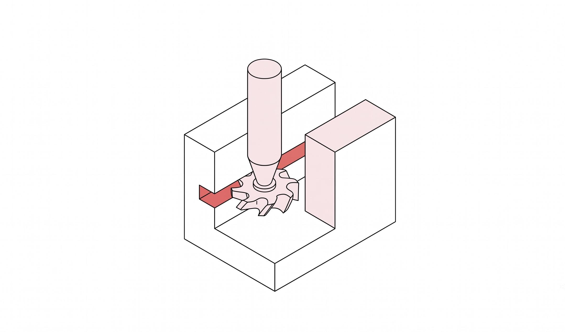
An undercut is a recessed feature that a cutting tool cannot reach from a normal top or side approach. Part of the surface sits behind a wall, under an overhanging lip, or inside a bore. In milling, the feature is wider inside than its opening.
A T-slot is the simplest example. A standard end mill cuts the narrow slot from above. The wider section below extends sideways under the surface. That lower section is the undercut.
A quick test is to picture a flashlight shining straight down onto the part. Any surface left in shadow is an undercut. To cut it, the tool must pass through the narrow opening and then cut sideways into the hidden wall.
Undercuts can be external or internal. An external undercut sits on the outside of a part, such as a relief groove next to a shaft shoulder. An internal undercut sits inside a bore, pocket, or housing, where the tool has less room.
In milling, a groove with open access is a standard feature, while the same groove hidden behind a shoulder is an undercut. The difference is how the tool reaches the material, not the shape. In turning, relief grooves at shoulders and thread ends are also called undercuts, even though they are easy to reach.
Why Are Undercuts Used in Machining?
Undercuts are added for function, not for looks. Each one solves a specific problem in how a part fits, seals, or holds together. A feature that does none of these jobs is a candidate for removal.
Part Retention
Some undercuts hold parts in place without extra fasteners. A dovetail slot locks a sliding part so it cannot lift out. A T-slot captures a bolt head, so mounting hardware can sit anywhere along a fixture or machine table. A retaining ring groove holds a snap ring, which locks a bearing or collar in place.
Seal Seating
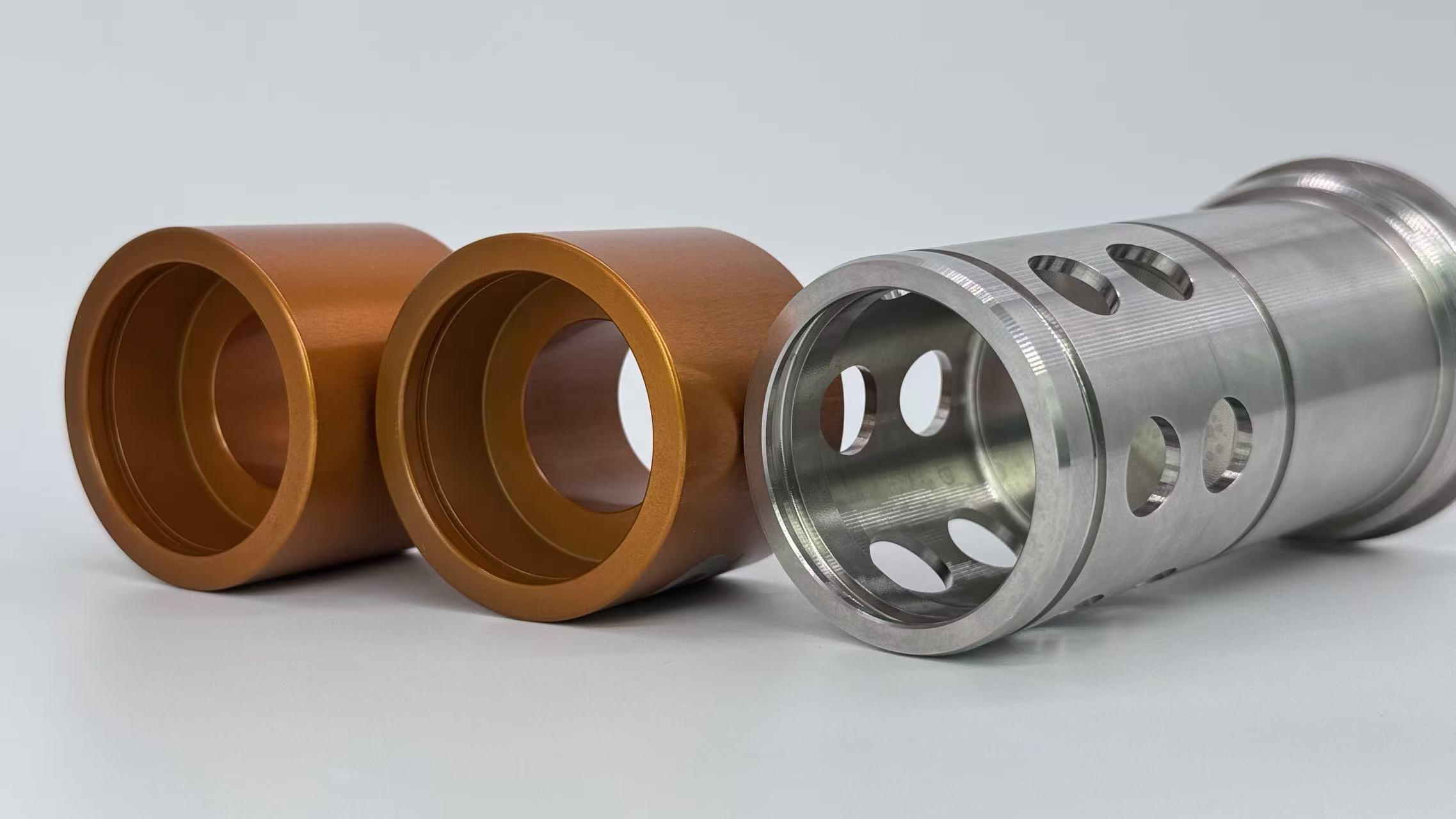
An O-ring needs a groove that holds it in position and sets how much it compresses. In hydraulic, pneumatic, and medical device parts, that groove is often cut inside a bore or on a shoulder face, where tool access is limited. Groove width, depth, and wall finish all affect sealing, and a poorly cut groove can cause leaks in the final product.
Clearance Relief
A relief groove gives a mating part or a tool room to finish its move. At the end of a thread, it lets the threading tool exit cleanly and lets a nut or fitting seat fully. At a shaft shoulder, it lets a bearing or collar sit flat instead of resting on the corner radius.
Stress Reduction
Sharp internal corners concentrate stress, and cracks tend to start there under repeated loading. A relief cut at a sharp transition can replace the corner with a controlled radius and spread the stress over a larger area. It only helps if the groove is well shaped, since a poorly cut one creates a new stress point.
Internal Recesses
A circular groove inside a bore can spread fluid around a shaft, and an internal chamber can give a sensor or moving part room to work. Because these recesses sit behind the bore wall, a standard end mill cannot cut them. The tool must reach in through the opening and cut outward.
Types of Undercuts
Undercuts are grouped by shape and by the job they do. The type decides which tool and machine fit best.
- T-Slot Undercut: A narrow slot at the surface that widens below it to hold a bolt head or sliding nut. A standard end mill cuts the straight slot first, then a T-slot cutter cuts sideways into the walls below.
- Dovetail Undercut: A groove with angled walls, wider at the bottom than at the opening. A mating part with the same angle slides in but cannot lift out. The cutter angle must match the drawing.
- O-Ring Groove: A rectangular channel that holds a seal. On a shaft or flat face it is open and easy to reach, but inside a bore it is hidden and becomes a true undercut.
- Thread and Shaft Relief: A narrow groove at the end of a thread or at the base of a shoulder. It lets the threading tool exit and the mating part seat flat. Most are external and cut on a lathe with a grooving tool, which makes them among the easiest undercuts to machine.
- Internal Bore Groove: A circular groove inside a hole, such as a retaining ring groove or an internal seal seat. Bore diameter limits cutter size, and groove depth sets the reach. These are among the hardest undercuts to cut and to inspect.
- Spherical Undercut: A curved, ball-shaped recess that holds a bearing ball or mates with a spherical surface, usually cut with a lollipop cutter.
Tools for Undercut Machining
Undercut tools put the cutting edge on a head wider than the neck behind it. Neck length and thickness set the reach and the stiffness.
Lollipop Cutters
A ball-shaped head on a thin neck cuts behind walls, into corners, and along curved hidden surfaces, which makes it the usual choice for spherical undercuts. Choose the shortest neck that clears the part, and use light passes.
T-Slot Cutters
A flat, disc-shaped head with cutting teeth cuts the wide lower section after an end mill has cut the straight slot. Chips pack easily in the closed groove, so heavy side loads and aggressive feeds risk breakage.
Dovetail Cutters
A cone-shaped cutter, widest at the tip, cuts the sloped walls of the groove, so the cutter angle sets the groove angle.
Keyseat and Slot Cutters
A keyseat cutter is a thin disc on a shank. It cuts narrow slots, such as keyseats, and ring grooves with low cutting force, because it removes little material.
Grooving Tools
A grooving insert on a lathe cuts shaft reliefs, thread reliefs, and O-ring grooves on the outside of a part, and an internal grooving tool does the same inside a bore. The part spins, so the tool follows a stable circular path. Thread mills cut threads on milled parts, and a relief groove at the thread end gives the tool room to finish.
How Undercut Machining Works
The machining process for undercuts follows the same basic flow as other CNC work. The difference is that tool access drives every step. Each stage is checked against one question: can the cutter reach the feature, cut it, and leave without hitting anything?
Geometry Review
The process starts with the part drawing or CAD model. The machinist checks whether the undercut is internal or external, open or blind, shallow or deep. Width, depth, corner radius, and surrounding wall thickness all matter.
The key check is the tool path: the cutter, shank, and holder must all enter, cut, and retract without touching the walls. A feature can look reachable in the digital model and still fail because the holder hits a wall. CAM simulation confirms this before any metal is cut. The review also sets the tool type and the machine.
Machine Setup and Workholding
Setup decides which machine runs the job. Round features such as shaft reliefs and bore grooves are usually turned on a lathe. T-slots, dovetails, and side features are milled. Parts with both turned and milled features may run on a mill-turn machine.
Workholding must keep the part rigid, since any movement shows up as size error in a hidden cut. Material selection changes the setup as well, since different materials cut very differently. Aluminum cuts freely and clears chips easily. Hard materials such as hardened steel, and tough alloys such as stainless steel and titanium, create more heat and cutting force inside a tight recess. They call for slower speeds, stronger tooling, and better coolant delivery.
Cutting Operation
Undercuts are usually cut after the main roughing, which removes material and opens up space for the tool. The undercut itself then takes lighter passes and shallower depths of cut than open milling, because a long, narrow tool bends easily under load.
Inspection
Many undercuts cannot be seen once the part is finished. A visual check can confirm the feature exists, but not its width, depth, radius, or position. Hidden features are usually measured with pin gages, bore micrometers, CMM probes, or custom gauges. Holding high accuracy in these features takes time, so tight tolerances should go only on functional surfaces.
Methods for Undercut Machining
Three manufacturing processes cover most undercut work. The choice depends on geometry, material, and order size.
Multi-Axis Machining (3-Axis to 5-Axis CNC Milling)
A 3-axis mill can cut many undercuts, because a T-slot or lollipop cutter enters through the opening and cuts sideways. The limit is access. If the shank or holder hits a wall on the way in, the machine has no other angle to try. A 4-axis or 5-axis machine rotates or tilts the part or the tool to approach from an angle that clears the wall, which allows a shorter, stiffer tool and fewer setups. Multi-axis work costs more in machine time and programming, and some geometry stays out of reach even on five axes.
Electrical Discharge Machining
Electrical discharge machining (EDM) uses sparks instead of a cutting edge to remove material. In sinker EDM, a shaped copper or graphite electrode erodes the part in dielectric fluid. No cutting force acts on the part, so thin walls do not deflect. EDM also cuts hardened steel that wears out cutters quickly, and the electrode can form tight internal corners. Wire EDM needs a through path, so sinker EDM is the usual choice for blind undercuts. The material must conduct electricity, the electrode must be made first and wears during the cut, and cycle times are usually longer than milling.
Manual Machining
Manual knee mills and engine lathes can cut simple undercuts, such as a shaft relief or a straight T-slot. This suits prototypes, repairs, and small runs, where programming a CNC machine costs more than the cut. Results depend on the operator, and holding the same size across many parts is hard. For complex or hidden shapes, CNC is the safer route.
Key Challenges in Machining Undercuts
These undercut challenges share one cause: the cutting edge works where the tool body can barely reach. Most manufacturing constraints below follow from that.
Tool Access Limitations in Complex Geometries
Overhanging ledges, deep pockets, and narrow openings all restrict the tool path. Every extra millimeter of undercut depth also needs another millimeter of reach. An undercut at the far wall of a deep, narrow pocket may be unreachable, because the tool shaft hits the near wall before the cutter arrives. Better tools cannot fix that. The geometry has to change.
Reduced Tool Rigidity and Deflection
Undercut tools have a thin neck behind a wider head, which makes them weak tools under side load. The cutting force acts far from the holder, so the longer the reach, the more the tool bends. Width and depth drift from the programmed size, walls carry chatter marks, and dimensional accuracy suffers. Lighter passes reduce the bending but add cycle time.
High Risk of Tool Breakage
A thin neck and a tight cutting zone leave little margin, so a sudden load spike can snap the tool. Packed chips, a heavy engagement, or a hard spot in the material can all cause one. A broken cutter inside a hidden recess is hard to remove and can scrap a nearly finished part.
Difficult Chip Evacuation
An undercut is a partly enclosed space, so chips have few paths out. The cutter recuts them, which adds heat, speeds tool wear, and scratches the wall instead of leaving a smooth finish. Coolant has the same problem, since it cannot easily reach an edge that sits behind a wall. Through-tool coolant or air blasts help. Burrs form at hidden edges for the same reason and are hard to remove afterward, so leave access for deburring.
Complex CAM Programming and Collision Risks
An undercut toolpath needs more care than an open one. The program must plan the entry, the sideways cut, and the retract so no part of the tool touches the wall. A small error can crash the tool into the lip above and damage the tool, holder, and part together. Simulation against the part model is the main safeguard.
Undercut Design Rules and Design Optimization
Most undercut cost is set in CAD. The four rules below apply design for manufacturability, so the feature can be machined cost effectively and clearance problems are caught before full production. Check them at the start of your next project.
Keep Undercuts Shallow to Cut Machining Time
Depth sets how far the tool must reach, and long tools bend more under load. A shallow undercut allows a shorter, stiffer tool and faster feeds, so make the feature only as deep as the seal, ring, or fit requires.
Use Standard Tool Sizes
A custom cutter brings high costs and long lead times, and it is hard to replace if it breaks mid-job. Design widths, radii, and angles around common cutter sizes. Snap ring and O-ring grooves already follow published dimensions, and so do shaft reliefs and thread undercuts, for example in DIN 509 and DIN 76. The machine shop can tell you which sizes it stocks.
Provide Entry Clearance
Leave the cutter a clear path in and out. The opening must be wide enough for the cutter head to pass, and there must be room for the shank, holder, and spindle nose, not only the cutting edge. Also leave space for coolant and chips to move.
Match Dovetail Angles
A dovetail cutter forms the groove angle directly, so the angle on the drawing must match a cutter that exists. Standard cutters come in fixed angles, and 45 and 60 degrees are among the most common. A non-standard angle may need a custom ground tool, which adds cost and programming time. The mating part must use the same angle, or it will fit loosely or not slide in.
How to Reduce or Avoid Undercuts
Some undercuts do real work, such as seating a seal. Others can be redesigned so the tool reaches the surface from an open side.
Simplify or Eliminate Features
Start by asking what the undercut does. If it does not improve fit, sealing, clearance, or locking, remove it. Many undercuts exist because they were the first shape someone sketched, not because the function required them. When the function is real, the three changes below often deliver it with simpler design solutions.
Open the Feature to One Side
A hidden groove can often become an open one if a wall is removed or the feature moves to an exposed face, so a standard end mill or grooving tool can cut it. Moving a seal groove from inside a bore to the outside of the mating shaft is a common example. Where a part must be locked, an open slot with a separate fastener may replace a T-slot or dovetail.
Split the Part at the Undercut
If the undercut is needed and cannot be opened, split the part through the middle of the feature. Each half then has open access, so a standard tool can cut it, and the two separate parts are fastened or bonded together afterward. The trade-offs are an extra assembly step and a joint, so alignment must be controlled with dowel pins, a step, or a close fit. Depending on geometry and volume, this is often cheaper than cutting the undercut directly.
Stack Parts to Form the Overhang
A third option is to split the part horizontally, at the top of the undercut. A separate plate then sits over the recess and forms the overhang. Because it is removable, a captive fastener or an internal component can be placed in the recess before the plate goes on. The cost is an extra part and fasteners.
Have a design with T-slots, dovetails, or internal grooves? Send your drawings or CAD files to Aria Manufacturing. Our engineers will review the geometry, point out features that add cost, and quote the part. Visit madearia.com to start a request.
