

 EU
EUModern mechanical parts rarely stay flat. Curved profiles, tapered walls, and intricate 3D contours show up across automotive, aerospace, and medical components, and standard face or pocket milling generally cannot shape them to the required accuracy and finish.
What Is Profile Milling?
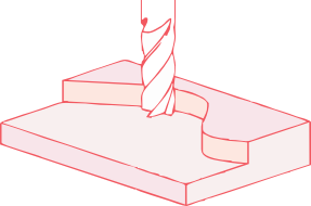
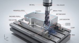
Profile milling is a CNC subtractive process that uses rotary multi flute tools moving along a defined path to generate specific interior or exterior contours on a workpiece. Unlike face milling, which focuses on flattening broad surfaces, or pocket milling, which clears bulk material from an enclosed cavity, profile milling engages both the peripheral edge and the bottom radius of the milling cutter along the boundary itself. This dual engagement lets it machine 2D, 2.5D, and full 3D geometries, including complex profiles that those other operations cannot reach.
The basic idea is similar to how a router follows a template in woodworking, but profile milling works with metals and other engineering materials that need tighter tolerances. In practice, this means guiding a rotating tool along a defined contour, engaging its side and bottom radius to cut precise shapes while holding tight tolerances.
The process gives real flexibility when a part combines elevation changes with curved or tapered walls, since the toolpath itself becomes the main driver of the final shape rather than a simple sweep across an open area. But this also means cutting forces stay active for the whole length of the contour, and they shift with geometry, feed direction, and engagement depth rather than staying even.
Long tool overhang, thin walls, long edges, and sharp internal corners all amplify this load variation, which is why toolpath planning and tool selection carry more weight here than in most other milling operations.
Done well, profile milling still delivers high geometric accuracy and a fine surface finish in a single setup. That combination is why it plays such a central role in the aerospace industry, showing up in ribs and turbine blades. The same level of accuracy also carries over to other fields, including mould cavities and orthopaedic implants.
How Does Profile Miling Work?
Profile milling relies on a progressive sequence of stages to turn raw stock into a finished component. Each stage targets a specific goal, whether that is material removal rate, geometric correction, or surface quality, and skipping one tends to show up as poor finish or a part that drifts out of tolerance later on.
Roughing
Roughing focuses on removing material at the maximum rate. Large depth of cut and high feed rates strip away excess material as fast as the tool and machine allow, and a bit of scrap is acceptable since precision is not the priority here. This stage typically leaves an uneven, step-like stock pattern on complex contours.
Semi-Roughing
Semi-roughing addresses that staircase pattern. Clearing away the bulk variations balances the cutting load for the passes that follow and keeps the next tool from inheriting uneven engagement.
Semi-Finishing
Semi-finishing removes the remaining stock variations and corrects geometric distortion left over from earlier passes. It leaves a uniform surface with a consistent material allowance, so the finishing tool cuts an even amount of material along the whole contour rather than an inconsistent one.
Finishing
Finishing uses fine feeds and shallow cuts to bring the part to its final dimensions. Tight tolerances, sharp edge definition, and low surface roughness are achieved at this stage. Because the tool removes only a thin, controlled layer, cutting forces stay lower and more predictable than in roughing.
Super-Finishing
Super-finishing is optional and most parts skip it. When a near-mirror surface is required, high-speed machining combined with micro-stepping delivers that result without manual polishing. Aerospace turbine components and optical mould inserts are typical cases where this stage earns its place.
Profile Milling Techniques and Toolpaths
Complex contours call for different toolpath strategies depending on part geometry, material and how much stock needs removing.
Traditional 2D Profiling
The tool steps down incrementally along the Z-axis, cutting the perimeter at each level. Arc lead-in and lead-out moves replace sharp direction changes at the start and end of each pass, which prevents dwell marks on the finished wall. This remains the standard approach for flat pockets, slots and simple profiles.
High-Feed Ramping
Rather than plunging straight down, the tool enters along a continuous angled path in the Z-axis. This keeps the cutter engaged throughout the approach and spreads wear more evenly across the flutes, making the whole pass more efficient. It also removes the non-cutting air moves that stepdown machining needs between passes, and keeps heavy plunge forces off the tool centre, which is the weakest point on most end mills.
3D Contour Milling
Once a surface has compound curvature, a ball-nose cutter moves in three, four or five axes simultaneously, following the true surface geometry instead of a series of flat steps. This is the method behind mould cavities, turbine blades and organic surfaces. Keeping tool engagement consistent along the path limits local heat build-up and holds dimensional accuracy across the surface.
Climb Milling vs Conventional Milling
The main difference between the two methods comes down to which direction the cutter rotates relative to the feed. Climb milling cuts in the same direction as the feed, which reduces rubbing and gives a better surface finish, so it’s commonly the default on rigid modern machines. Conventional milling cuts against the feed instead, easing into the material rather than striking it head-on, which makes it the safer choice on cast iron or forged stock with a hard oxide scale.
Trochoidal Profiling
For narrow slots and pocket corners, the tool follows small circular loops while advancing forward, rather than cutting full-width. This keeps chip load constant and sharply reduces radial engagement (Ae). With less of the flute in contact at any moment, heat has less chance to build up, which allows higher feed rates without risking tool breakage.
Choosing the Right Cutting Tools
Tool choice follows the machining stage, and there’s a wide range of geometries and coatings to pick from. A roughing tool needs to survive heavy loads, while a finishing profile milling cutter needs to hold geometry and surface quality.
Indexable Profile Cutter
These carry round or shaped indexable inserts on a steel or carbide body. The round insert spreads cutting force over a wide contact area, which gives it the edge strength to handle shock loading on tough or cast material. Once an edge wears, the insert indexes to a fresh cutting position or gets swapped out, so the cutting head outlasts a solid cutter under the same workload. This makes indexable cutters the standard choice for stripping bulk material in roughing.
Ball-Nose End Mills
The hemispherical tip keeps continuous contact with the surface regardless of how it curves, which is why these are the standard tool for semi-finishing and finishing 3D contours.
One detail worth knowing: cutting speed at the exact centre of a ball-nose tool drops to zero, since that point isn’t moving relative to the surface. Cutting near dead centre on shallow or flat areas causes rubbing rather than shearing, which accelerates wear and dulls the finish. Tilting the spindle or programming multi-axis toolpaths keeps the cutting action away from that point.
These tools come in solid carbide and exchangeable-head versions. The exchangeable-head type is worth it on long runs, since only the worn tip needs replacing.
Solid Carbide End Mills
Machined from a single piece of tungsten carbide, these tools have high core rigidity, which adds stability and limits deflection during finishing passes. On tall vertical walls or deep features, any deflection shows up directly as a dimensional error, so stiffness matters more here than almost anywhere else in the process. Carbide also holds its edge at higher cutting speeds than high-speed steel, and a suitable coating helps it shed heat and resist friction over longer runs.
High-Feed Cutters
A small entering angle at the cutting edge directs most of the force axially, up through the spindle, rather than sideways against the tool. With less radial load pushing the tool off course, it can run at much higher feed rates without deflecting or chattering. This suits aggressive roughing on rigid machines, and pairs naturally with high-feed ramping toolpaths for fast bulk removal ahead of semi-finishing.
Coating and grade selection matter too. TiAlN and AlCrN coatings hold their hardness at the high temperatures generated in titanium, nickel superalloys and hardened steels, while DLC coatings resist the built-up edge that non-ferrous metals like aluminium tend to cause on a cutting edge. The exact grade still depends on the specific material and application, so match the coating to the job rather than defaulting to one across the board. The consistent rule across all four tool types is to match the tool to the stage. A finishing tool pushed into roughing loads fails fast, and a roughing tool left on for finishing leaves a poor surface.
Because profile milling cuts with a round rotating tool, it has one geometric limit worth flagging at the design stage: any internal corner can only be machined with a radius at least half the cutter’s diameter (R ≥ D/2). A drawing that calls for a sharp, perfectly square internal corner can’t be profiled directly with a single tool; it needs either a relief groove at the corner or a secondary process, such as EDM, to finish it. Flagging this radius requirement during design, rather than after the part reaches the machine shop, avoids rework and delays.
Key Machining Parameters
Getting profile milling right comes down to a small set of parameters. Getting any one of them wrong shows up quickly in tool life or surface finish.
Cutting Speed (Vc)
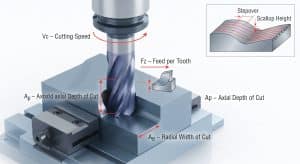
This is the speed at which the cutting edge moves through the material, set according to material hardness and tool coating. Push it too high and the edge overheats and wears fast. Set it too low and the tool rubs instead of shearing, which is just as damaging over time.
Feed per Tooth (Fz)
This sets how much material each flute removes on every rotation. Keeping the right chip load matters most on alloys prone to work hardening, such as stainless steel or titanium, where a light feed rubs the surface and hardens it rather than cutting cleanly. Too high a feed causes chip packing in deep features and risks chipping the edge.
Axial Depth of Cut (Ap) and Radial Width of Cut (Ae)
Ap is how deep the tool cuts vertically, Ae is how much of the tool diameter engages radially. A useful pairing is high Ap with small Ae. This keeps chatter down and lets heat move into the chip rather than the tool, which allows faster feed rates than a wide, shallow pass would permit. Finishing passes reverse this logic, pulling both values back to protect the surface and hold tolerance.
Stepover and Scallop Height
Stepover is the distance between adjacent toolpaths on a 3D surface, and it directly controls scallop height, the small ridges left between passes on curved contours. A smaller stepover leaves a smoother surface but adds machining time, since more passes are needed to cover the same area. The right stepover is usually set by the tolerance the finished surface needs to meet, not by a fixed rule.
Industry Applications of Profile Milling
Profile milling shows up wherever a part needs an accurate contour rather than a simple flat or round feature.
Aerospace
Weight-reduction pockets, structural ribs, turbine blades and engine casings all rely on profile milling to hold tight tolerances in tough alloys such as titanium and nickel superalloys. These materials resist heat well, but that same toughness makes precise toolpath control essential, since poor cutting parameters here risk both tool failure and damage to the part’s structural integrity.
Automotive
Engine blocks, transmission housings, suspension components and performance parts all carry profiled surfaces that need to seal, mate or move against other parts. Profile milling also supports consistent mass production of cast or forged components, holding the exact fitment needed for reliable performance under continuous mechanical stress.
Mould and Die Making
Injection mould cavities, core inserts and stamping die parting lines are some of the most demanding profile milling work there is, machined into hard die steels where any error transfers directly onto every part produced afterwards. Getting the toolpath and surface finish right at this stage cuts down on the manual polishing and bench work that would otherwise be needed to finish the tool.
Medical Devices
Orthopaedic implants, artificial joints and surgical tools need both dimensional precision and a smooth surface, machined from biocompatible materials such as titanium and cobalt-chrome. These parts often carry complex organic curves that need to match human anatomy closely, so multi-axis profiling is standard here to hold accuracy across surfaces that a simpler toolpath couldn’t reach.
Profile milling rewards experience as much as equipment. Getting from a rough blank to a finished contour with the right tolerance and surface finish depends on toolpath choices, tool selection, and machining parameters all working together, not just one good machine. If you’d like to see these choices play out in practice, you can watch videos of the process on our site.
If you’re planning a part that needs this level of contour accuracy, Aria Manufacturing’s engineering team can review your design and recommend the right machining approach before you commit to production. Get in touch for a quote or send over your drawing for a feasibility check.
-100x100.jpg)