

 EU
EUShafts rarely need just one diameter. A bearing might sit on one end, a gear in the middle, and a coupling on the other, and each of these needs a different fit along the same shaft. Step turning is the lathe operation that cuts a workpiece down to these multiple diameters in one setup, with a sharp shoulder marking each transition.
This guide is written for mechanical engineers, product designers, and procurement managers who need to understand how step turning works, what tooling it requires, and where it fits against other lathe operations like taper turning and straight turning.
What is Step Turning?
Step turning is a lathe operation that cuts a rotating workpiece down to two or more distinct diameters along its length. Each diameter change forms a sharp, perpendicular shoulder rather than a gradual slope. This square-cornered transition is what separates step turning from other turning operations and gives the process its name.
The shoulder is not just a cosmetic feature. It acts as a positive mechanical stop during assembly. A bearing, gear, or pulley pressed onto a shaft seats against the shoulder and holds its axial position under load. Without that shoulder, these mating components would need separate retaining features like circlips or collars.
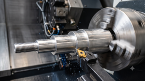
Machinists perform step turning on manual engine lathes or CNC turning centers. On a manual lathe, the operator positions the tool and controls feed by hand for each section. On CNC equipment, the tool follows programmed paths to remove material in passes, producing exact diameters and clean shoulders in one continuous setup.
The corner where two diameters meet also affects how stress distributes across the shaft under load. A sharp 90-degree internal corner concentrates stress at that point, so engineers often call for a small radius or relief groove at the shoulder to reduce the risk of fatigue failure.
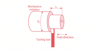
How does CNC Step Turning Work?
CNC step turning follows a fixed sequence, moving from raw stock to a finished multi-diameter shaft in one setup. Precise tool paths, tight CNC control, and rigid workholding keep every step within its target tolerance.
Workpiece Setup on CNC Lathes
The raw bar stock is secured in a three-jaw chuck or collet chuck, gripping the outer diameter firmly. Longer workpieces need tailstock support at the free end to prevent deflection, vibration, and chatter during heavier cuts. Proper alignment at this stage matters, since any runout relative to the workpiece axis carries through to every step cut afterward, and every diameter needs to stay true to that same axis from the first cut to the last.
Parameter Configuration and Tool Positioning
The machine controller runs a G-code program that sets spindle speed, feed rates, depth of cut, and tool offsets. Cutting speeds and feed rates are chosen based on the workpiece material, tool geometry, and insert coating, balancing cycle time against tool life. Tool positioning is referenced from a fixed datum on the workpiece, usually the faced end.
Facing Operation
Before any diameter is cut on the cylindrical part, the end of the workpiece is faced to create a flat surface perpendicular to the spindle centerline. This face becomes the zero point for every length measurement that follows. An uneven or skipped facing pass throws off every step position down the line.
Rough Machining Process
Material is removed in heavier passes along the axis, bringing each section of the shaft’s varying diameters down close to its final size. Roughing prioritizes speed over finish, so a thin layer of stock is deliberately left on the outer diameters and shoulders for the finishing pass.
Sequential Step Formation
The tool profiles each diameter in turn, moving along the Z-axis to the required length before retracting along the X-axis to form the shoulder face at each transition zone. Correct tool clearance angles matter here, since the wrong angle lets the tool rub against the vertical wall of these shoulder transitions during retraction. This repeats section by section until every step on the drawing has been roughed out.
Finishing and Shoulder Machining
A finishing pass brings each diameter and shoulder to its exact dimension, sharp corners, and specified surface roughness, meeting the tolerance requirements called out on the drawing. Machinists often add small fillets or undercut grooves at the shoulder intersections during this secondary finishing pass to remove stress concentration points.
The Necessary Tools for Step Turning Process
Step turning can be done with a basic tool set, but each tool has a specific role in getting from raw stock to a finished stepped shaft.
Turning Tools
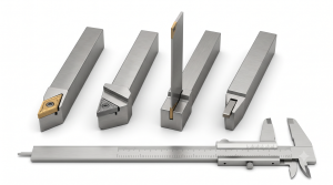
The turning tool handles the bulk of the material removal. It is a single-point cutting tool, usually fitted with a replaceable carbide or high-speed steel insert. Tool selection changes with the operation: roughing passes typically use a stronger insert geometry built for heavy cuts, while finishing passes switch to an insert with a smaller nose radius to reduce cutting resistance and improve surface finish.
Facing Tools
Facing tools cut across the end of the workpiece to create the flat reference surface that all length measurements are taken from. The cut is a radial pass, typically working from the outer edge toward the center, though the direction can reverse on hollow or tubular stock. Many shops use the same turning tool for facing rather than a dedicated facing tool, depending on the insert geometry. Getting this face flat and true matters, since every step length gets measured from it.
Parting Tools
A parting tool has a narrow, rectangular blade with sharp cutting edges. Because the blade has limited lateral rigidity and significant overhang, it’s used almost exclusively for its core job: cutting straight into the workpiece to separate a finished part from the remaining stock at the end of the cycle. Using it for anything beyond that, such as cutting a groove mid-shaft, raises the risk of chatter.
Grooving Tools
Grooving tools cut narrow recesses into the shaft, often used for retaining rings, O-ring seats, or a small relief groove right at a shoulder. That relief improves assembly fit by letting a bearing or retaining ring seat flush against the shoulder instead of catching on a corner radius. In step turning, a grooving tool is also the better choice for cutting an initial groove at a step transition before the turning tool removes the rest of the material, since its geometry handles that kind of plunge cut with more stability than a parting tool. Not every step-turned shaft needs grooving, but it comes up often on parts with retaining features.
Measuring Instruments
Measurement happens throughout the process, not just at the end. Vernier calipers handle quick in-process checks, accurate to about the second decimal place. Outside micrometers give tighter control over step diameters, typically to the third decimal place. Depth micrometers and, on higher-precision work, optical comparators are used to check step lengths and shoulder squareness. Dial indicators are useful before machining starts too, for checking runout on longer shafts where deflection can throw off later steps.
Advantages and Limitations of Step Turning
Advantages
- Fewer setups: all diameters are machined in one clamping, which keeps sections concentric and cuts labor time.
- Lower cost: costs less than straight turning each diameter as a separate operation with repeated repositioning.
- Fast production: well suited to CNC automation for higher-volume runs.
Limitations
- Setup sensitivity: any misalignment in the initial clamping or reference face carries through to every step cut afterward.
- Material waste: large differences between step diameters mean more stock gets cut away and discarded.
- Manual accuracy risk: on non-CNC lathes, results depend heavily on operator skill and in-process measurement.
What Materials can be used for Step Turning ?
Most machinable metals and several engineering plastics work well for step turning. Material choice usually comes down to how well the stock holds up under cutting forces without deflecting, and how well it can hold the tolerance requirements called out for each step, which matters more on longer, high-aspect-ratio shafts.
| Material | Common Grades | Why It’s Used |
|---|---|---|
| Carbon and alloy steel | 1045, 4140, 4340 | Good strength and wear resistance, common for drive shafts and industrial spindles |
| Stainless steel | 304, 316, 17-4 PH | Corrosion resistance with high tensile strength, needs sharp inserts to manage work hardening |
| Aluminum alloy | 6061-T6, 7075-T6 | Fast machining, low tool wear, favored for lightweight components |
| Brass and copper alloy | C36000 (free-cutting brass) | Cuts cleanly at high speed, common for fittings and bushings |
| Titanium | Ti-6Al-4V (Grade 5) | High strength-to-weight ratio, needs lower cutting speeds and coolant control |
| Engineering plastics | Delrin (POM), nylon, PEEK | Lightweight and non-conductive, needs lighter cuts to control heat and deflection |
Applications of Step Turning
Step turning shows up wherever a rotating part needs more than one diameter to seat mating components along its length. A few industrial applications account for most of that demand, and the examples below cover the most common ones.
Automotive Drive Shafts
Drive shafts and axles support universal joints, differential gears, and wheel hubs, each at a specific point along the shaft. Step turning produces these shoulder transitions in one setup, which keeps the shaft concentric across all sections and holds correct axial location under high torque.
Industrial Spindles
Machine tool spindles use stepped sections to form bearing seats, drive pulley mounts, and other functional interfaces. Dimensional consistency across every step matters here, since it directly affects spindle runout under continuous operation.
Motor Rotors and Shafts
Motor shafts typically need different diameters for rotor laminations, bearing journals, cooling fans, and the output coupling. Each component slides over a smaller diameter and seats against its own shoulder, so step turning keeps every section aligned to a single centerline and reduces vibration once the motor runs.
Threaded Fasteners and Pins
Some fasteners and pins, including heavy-duty bolts, alignment dowels, and clevis pins, use a stepped profile to separate a threaded section from a smooth pilot surface. Step turning handles this diameter transition before threading or finishing is added.
Aerospace Components
Actuator shafts, landing gear pivot pins, and turbine control linkages often combine step turning with high-strength alloys and tight tolerances. The shoulders on these parts carry significant shear load while supporting weight reduction goals, and the transition zones between diameters frequently need a specified radius or relief to meet fatigue requirements under repeated load cycles.
Step Turning vs Other Types of Turning Tool
Step turning is one of several lathe operations, and the method is often confused with others that also change a shaft’s diameter or profile. Here’s how the difference plays out in practice.
Step Turning vs Straight Turning
Straight turning cuts a workpiece down to a single, uniform diameter along its entire length, with no sharp transitions anywhere on the part. The tool feeds parallel to the axis and stays at one depth, removing material evenly across the cut . Because step turning finishes every diameter in one setup, it also tends to cost less than machining each diameter as a separate straight-turning operation with repeated clamping.
Step Turning vs Taper Turning
Taper turning produces tapered transitions, a gradual, angled reduction in diameter that creates a conical surface rather than a sharp shoulder. It’s commonly used for tool holder tapers or shaft ends that need to seat and self-locate inside a matching bore.
Step Turning vs Contour Turning
Contour turning follows a curved or irregular profile along the workpiece, producing shapes like radii, fillets, or decorative contours rather than flat cylindrical sections. This requires simultaneous X and Z axis movement on a CNC lathe to trace the curve. Step turning, by contrast, produces flat cylindrical sections connected by sharp shoulders, with no continuous curve involved. Contour turning suits parts where the profile itself is functional or aesthetic, while step turning suits parts where distinct, fixed diameters are what matters.
Step Turning vs Grooving
Grooving cuts a narrow recess into the workpiece using a radial plunge, typically for retaining rings, O-ring seats, or relief cuts. It removes a small, defined width of material at one location rather than reducing the diameter over a length. Step turning, on the other hand, reduces the diameter over an extended section of the shaft, with the tool feeding mainly along the Z-axis rather than plunging on the X-axis. The two often appear on the same part, with grooving added at a shoulder or along a step to serve a specific retaining or sealing function that step turning alone doesn’t provide.
FAQs
What is CNC machining?
CNC machining is a subtractive manufacturing process where computer-controlled machine tools, such as lathes, mills, and routers, cut raw material into a finished part. The system takes a CAD design and converts it into a set of numerical commands that control the tool’s movement. CNC turning, which includes step turning, is the branch of CNC machining that works with rotating parts on a lathe.
What is a good CNC program for step turning?
A good CNC program for step turning starts with a clear reference datum, usually the faced end of the workpiece, and defines every step position and diameter relative to that point. It separates roughing from finishing, often using dedicated canned cycles such as G71 for roughing and G70 for finishing to keep the code structured and reduce cycle time. Constant surface speed control (G96) with a spindle speed clamp (G50) helps maintain consistent cutting conditions across the different diameters in a single part. The program also needs safe tool retract clearances at each shoulder, so the tool doesn’t rub against the vertical face.
What does taper turning mean?
Taper turning is a lathe operation that reduces a workpiece’s diameter at a uniform, gradual rate along its length, producing a conical profile instead of a straight cylinder or a right-angle step. It’s used for components like Morse tapers, machine spindle bores, and conical pins that need a precise friction-locking fit. Unlike step turning, which forms sharp shoulders, taper turning uses an angled tool feed, either through a compound slide set to a specific angle or through CNC-interpolated movement.
-100x100.jpg)