

 EU
EUComputer Numerical Control (CNC) programming is the backbone of modern automated manufacturing. From aerospace components to medical implants, high-precision machining relies on digital instructions that tell CNC machine tools exactly how to move, cut, and finish raw materials.
Whether you are an aspiring machinist, a mechanical engineer, or an sourcing manager looking to understand automated production, this comprehensive guide will walk you through the fundamentals, types, operational workflows, and a step-by-step learning path for CNC programming.
What is CNC Programming?
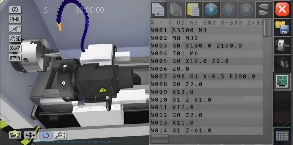
CNC programming is the process of creating a sequence of encoded instructions (primarily G-code and M-code) that controls the automated movements and operating functions of a CNC machine tool (such as a mill, lathe, or router).
At its core, a CNC program acts as the digital translator between a 3D CAD design model and physical machinery. Instead of a machinist manually turning handwheels to cut metal, the CNC program specifies exact coordinates, spindle speeds, feed rates, tool changes, and coolant flow. This automation ensures repeatable accuracy, tight tolerances, and efficient volume production.
Types of CNC Programming
Depending on component complexity, production volume, and available hardware/software, machinists use three primary methods to program CNC machines:
Manual Programming
In manual programming, the programmer writes every line of G-code and M-code directly into a text editor or at the machine control panel. The programmer reads the engineering drawing, calculates coordinates, and codes each movement by hand.
This is the most fundamental method. It gives full, direct control over every instruction the machine executes. No software licence required. No file conversion. Just code and cut. It works best for simple geometries, short production runs, or quick edits on the shop floor.
- Pros:Complete control over machine code, zero software cost, ideal for troubleshooting and small modifications.
- Cons:Time-consuming, prone to calculation errors, impractical for complex 3D surfaces.
CAM Programming (Computer-Aided Manufacturing)

CAM software generates toolpaths and post-processed G-code automatically from a 2D drawing or 3D CAD model. The programmer imports geometry, selects tools, defines cutting strategies, and sets machining parameters inside a visual interface. The software handles the rest.
Common platforms include Mastercam, Fusion 360, SolidCAM, and Siemens NX. They support multi-axis operations, complex surface machining, and advanced strategies like high-speed milling. Built-in simulation catches collisions and errors before any real cutting happens. This is the industry standard for complex 3D parts, multi-axis work, and high-volume production.
- Pros:Eliminates manual calculation errors, enables advanced toolpath strategies, includes visual collision simulation.
- Cons:High software licensing costs, requires solid machining knowledge to set parameters correctly.
Conversational Programming
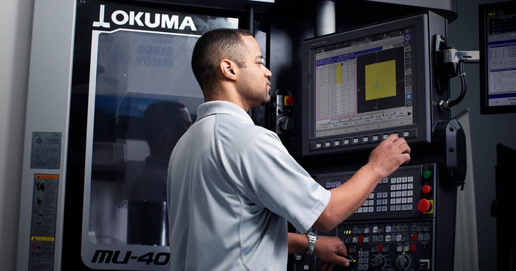
Conversational programming is built into the CNC machine controller itself. Instead of writing raw G-code, the operator fills in on-screen menus and dialogue boxes. The controller generates the code internally.
Well-known systems include Mazatrol (Mazak), Manual Guide i (FANUC), and ShopMill/ShopTurn (Siemens). The operator selects an operation type, enters dimensions, picks a tool, and starts cutting. No external software needed. This makes it the fastest path from drawing to first part, especially in job shops and prototype environments where turnaround matters more than optimisation.
- Pros:Minimal programming knowledge required, no software licence cost, fastest setup time.
- Cons:Limited capability for complex 3D contours and multi-axis work.
How Does CNC Programming Work?
CNC programming works in two key steps. First is design and translation. A 3D CAD model or engineering drawing is converted into machine-readable G-code and M-code that define the part geometry and operational instructions. This is done manually or through CAM software.
Second is execution and control. The machine controller reads these codes sequentially, commanding the motorised axes, regulating spindle speed and feed rate, triggering tool changes, and managing coolant flow to remove material with high precision and minimal human intervention.
Step-by-Step Guide: How to Learn CNC Programming
Mastering CNC programming requires a balanced understanding of geometric theory, machining technology, and software tools. Here is a progressive learning roadmap.
Step 1: Understand Engineering Drawings and Tolerances
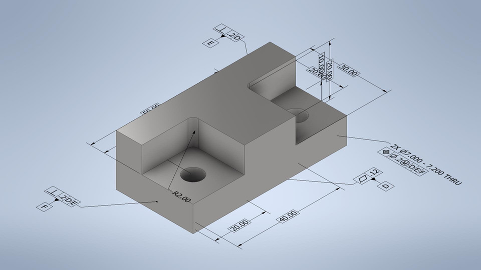
Before writing a single line of code, you must know how to read blueprints and technical drawings.
GD&T (Geometric Dimensioning and Tolerancing): Learn key concepts like datum references, position tolerances, flatness, and runout. These symbols define how much deviation is acceptable in form, orientation, and position. Misreading a tolerance means scrap parts or rework.
Unit Systems: Be comfortable converting between Imperial (inches) and Metric (millimetres). Many shops work in both, and mixing them up is a costly mistake.
Part Geometry: Identify critical dimensions, surface finish requirements, and datum origins (X0, Y0, Z0). Every CNC programme references a zero point. If you cannot locate it on the drawing, you cannot programme the part.
Step 2: Master Core CNC Codes (G-Code and M-Code Basics)
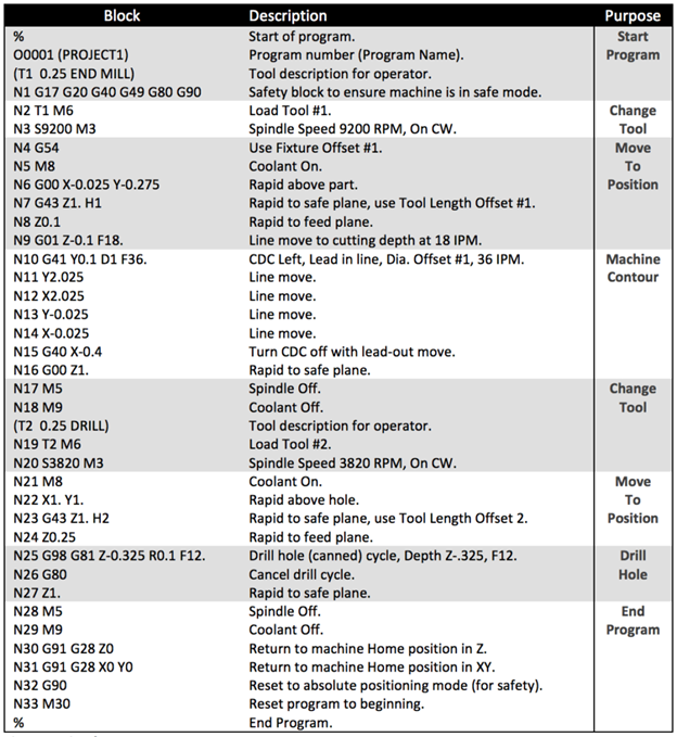
G-codes direct motion. M-codes control machine functions. You do not need to memorise hundreds of codes. Understanding the core set is mandatory for debugging, manual editing, and reading CAM-generated output.
Core G-Codes (Preparatory Functions)
G00 (Rapid Traverse): Moves the tool at maximum speed to a specified position without cutting. Used for repositioning above the part or between operations.
Example: G00 X50.0 Y25.0 Z5.0
G01 (Linear Interpolation): Moves the tool in a straight line at a specified feed rate (F) to perform a cutting operation. This is the most common cutting command.
Example: G01 X100.0 Y50.0 F200
G02 / G03 (Circular Interpolation): G02 moves the tool in a clockwise arc. G03 moves it counter-clockwise. The I, J, K values define the arc centre, or R specifies the radius directly.
Example: G02 X30.0 Y30.0 I10.0 J0.0 F150
G90 / G91 (Positioning Modes): G90 sets absolute positioning. All coordinates reference a fixed programme origin (0, 0, 0). G91 sets incremental positioning. Each coordinate is relative to the tool’s current position. Most programmes default to G90.
Core M-Codes (Miscellaneous Functions)
M03: Spindle on, clockwise rotation. M04: Spindle on, counter-clockwise rotation. M05: Spindle stop.
Example: M03 S3000
M08 / M09: M08 activates flood coolant. M09 turns coolant off. Coolant is critical for chip evacuation, temperature control, and surface finish quality.
M30 (Programme End and Reset): Stops execution and rewinds the code to the top. The machine turns off the spindle and coolant, and returns to a ready state.
Essential Coordinates and Parameters
X, Y, Z: The primary linear axes defining spatial movement in 3D space. X and Y control horizontal movement. Z controls depth in milling or longitudinal movement in turning.
F (Feed Rate): Sets the cutting speed of tool movement in mm/min for milling or mm/rev for turning. Correct selection directly affects surface finish, tool life, and cycle time.
S (Spindle Speed): Specifies the rotational speed of the spindle in RPM. Higher speeds suit smaller tools and softer materials. Lower speeds suit larger tools and harder materials.
T (Tool Select): Identifies the specific cutting tool number in the tool carousel.
Example: T01 M06 (Select tool 1 and execute tool change)
Step 3: Learn Machining Processes and Key Differences
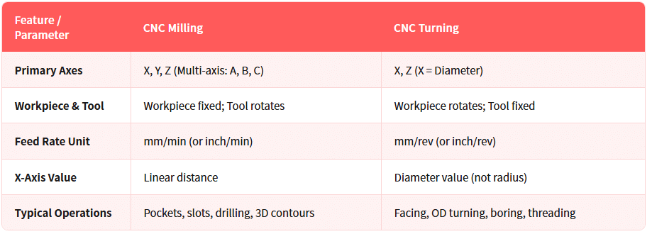
Understanding how metal is actually cut matters as much as knowing the code. The two most fundamental CNC processes are milling and turning. Their programming logic differs because the mechanics differ.
Milling uses a rotating cutting tool while the workpiece is clamped to the table. The tool moves across X, Y, and Z axes to remove material. Programming involves toolpaths for flat surfaces, pockets, slots, holes, and 3D contours.
Turning uses a stationary cutting tool while the workpiece rotates in a chuck. The tool moves along Z (length) and X (diameter) to shape cylindrical features. Programming focuses on facing, OD turning, boring, grooving, and threading.
The key differences at a glance:
Step 4: Master CAM Software
Once manual coding and machining fundamentals are solid, move to CAM software. Fusion 360 is a good starting point with free personal licences. Mastercam, SolidCAM, and Siemens NX are other widely used options.
The core CAM workflow:
- Import 3D CAD geometry.
- Define stock dimensions and Work Coordinate System (WCS).
- Select tools and operations (2.5D roughing, 3D profiling, drilling).
- Set speeds, feeds, and depth of cut.
- Generate and simulate toolpaths.
- Post-process to machine-specific G-code.
Start with simple 2.5D parts, then progress to 3D surfaces. Compare CAM output against hand-written code to understand what the software is doing behind the scenes.
Step 5: Setup and Dry Run Simulation
Never run untested code on a real machine.
Start with CAM simulation. Check for gouges, collisions, air cuts, and incorrect depths. Then load the programme into the machine controller and run a dry run with no workpiece loaded or Z offset raised well above the stock. Set rapid override to its lowest speed and keep a finger on the feed hold button at all times.
On the first real cut, use single-block mode. It executes one line at a time so you can stop immediately if anything looks wrong. After the first part is complete, measure critical dimensions, adjust offsets if needed, and refine the programme before starting production.
Common CNC Programming Mistakes to Avoid
Even experienced programmers make errors. Watching out for these common pitfalls saves time and prevents costly damage.
- Incorrect Tool Offset or Z-Height Zeroing.Setting Z0 incorrectly can cause the cutting tool to crash directly into the machine table or vise jaws. Always verify offsets before the first cut.
- Missing M05 / M09 Before Tool Changes.Changing a tool without stopping the spindle or turning off coolant leads to mechanical jams or hazardous shop conditions. Build the habit of calling M05 and M09 before every tool change command.
- Wrong Feed and Speed Calculations.Cutting too fast burns tools instantly. Cutting too slow causes work-hardening, chatter marks, and inefficient cycle times. Always calculate speeds and feeds based on material, tool diameter, and depth of cut.
- Confusing Incremental (G91) with Absolute (G90).Mixing up positioning modes results in unpredictable tool paths and potential crashes. Default to G90 and only switch to G91 when specifically needed.
- Ignoring Rapid Movement Safety Heights.Failing to command a clearance height during rapid positioning (G00) causes tools to hit clamps, fixtures, or unmachined stock. Always set a safe retract height above the workpiece.
- Wrong Arc Direction (G02 vs G03).Swapping clockwise and counter-clockwise arc commands produces incorrect geometry and can drive the tool into the workpiece. Double-check arc direction against the drawing before running.
Conclusion
CNC programming bridges digital engineering and physical manufacturing. By understanding basic G/M codes, mastering core cutting parameters, and using modern CAM software with strict simulation practices, you can reliably produce high-precision machined parts.
Looking for reliable, high-precision CNC machining services for your custom parts? At Aria Manufacturing, our experienced CNC engineers and programmers deliver tight-tolerance components through advanced multi-axis CNC milling, CNC turning, and full production runs with fast turnarounds. Contact us today or upload your 3D CAD file for a free quote and technical DFM analysis.
