

 EU
EUWhen we need to machine a large flat surface fast, the plain milling process is usually my first choice. It removes material quickly on most level surface, the tooling cost is low, and the setup is simple enough that even a newer machinist can run it safely.
Below, we cover how the plain milling process works step by step, the cutter types I rely on, how plain milling compares to other milling operations, and the real advantages and drawbacks you should know before you put a part on the machine.
What Is Plain Milling?
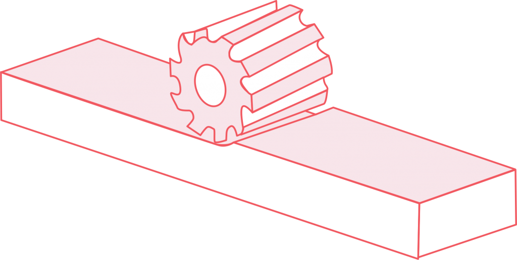
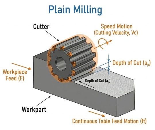
Plain milling is a milling process that uses a rotating cutter to remove material from a flat surface. The cutter’s rotation axis runs parallel to the workpiece surface, and only the machining edges on the outer circumference of the cutter do the work. That is why this milling process is also called slab milling, surface milling, or peripheral milling.
The purpose of the plain milling process is straightforward. I use it to produce a level surface parallel to the cutting axis of the tool. The plain milling process is not built for slots, pockets, or complex 3D shapes. It is built to clear large level surfaces fast, and it does that better than most other milling techniques.
In a typical setup, the surface finish I can achieve ranges from Ra 3.2 to 6.3 μm on a roughing pass, and Ra 0.8 to 1.6 μm on a finishing pass with the right plain milling cutter and parameters.
How the Plain Milling Process Works
Here is how I run a plain milling process from start to finish.
Step 1: Choose the Cutter
I decide between a light-duty and a heavy-duty plain milling cutter based on how much material I need to remove and how smooth the finish needs to be. I also consider the product material, the cutter material (HSS vs. carbide), and whether a coating is needed. More on these choices in the cutter section below.
Step 2: Mount the Cutter on the Arbor
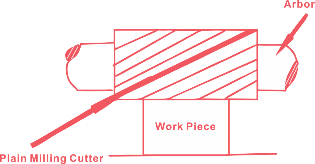
The plain milling process usually runs on horizontal milling machines. I slide the plain milling cutter mounted on the arbor, which is driven by the milling machine spindle. The arbor is supported at both ends: the milling machine spindle holds one end, and the overarm bracket holds the other. Arbor mounted cutters need rigid support at both ends to keep chatter out of the cut.
Step 3: Secure the Workpiece
I clamp the part directly to the table, hold it in a vise, or set it on an adjustable angle plate. For angled cuts, the adjustable angle plate lets me tilt the workpiece to the exact degree I need. The top face of the workpiece needs to sit as a flat surface parallel to the table.
Step 4: Check the Alignment
Before I cut anything, I check that the table is level and the workpiece is square to the tool axis. Skipping this step in the plain milling process gives me an uneven cut every time.
Step 5: Set the Cutting Parameters
I set cutting speed, feed rate, and depth of cut based on the workpiece material and the plain milling cutter. I also choose between climb milling and conventional milling at this stage. If the product material is hard or abrasive, I adjust cutting parameters accordingly by lowering the cutting speed and increasing the feed per tooth.
Step 6: Make the Cut
The rotating cutter spins at the set cutting speed, the table feeds the workpiece into it, and the cutting edges on the periphery peel material off the top flat surface. I run multiple passes when the stock allowance is large. After each pass, I check the surface quality and adjust cutting parameters if needed.
Conventional Milling vs. Climb Milling
Every plain milling operation uses one of two feed directions. The choice affects surface finish, tool life, and how much force the machine tool has to handle.
Conventional Milling (Up Milling)
In conventional milling, the rotating cutter turns against the feed direction. Each cutter tooth enters the workpiece material at zero chip thickness and exits at maximum thickness. This gradual engagement produces more friction and more heat at the start of each cut, which can cause work hardening on some product materials.
I use conventional milling in the plain milling process when:
- The milling machine has backlash in the table leadscrew
- I am working with hard or abrasive product materials that benefit from gradual cutter tooth engagement
- The workpiece surface has a hard scale or oxide layer that I want the cutting edge to get under before the main cut begins
Climb Milling (Down Milling)
In climb milling, the rotating cutter turns with the feed direction. The cutting edge enters the product material at maximum chip thickness and exits at minimum. This produces less friction, less heat, and a better surface finish.
I use climb milling in the plain milling process when:
- The machine tool is rigid and has no backlash (most modern CNC milling machines qualify)
- I want the best possible surface quality
- I want to extend tool life, because the cutting forces push the workpiece into the table instead of lifting it
For most CNC plain milling operations, I default to climb milling. The finish is better, tool wear is lower, and the cutting forces are more stable.
Types of Plain Milling Cutters
The plain milling cutter is the most important choice in this milling process. I work with three main types.
Straight-Tooth Plain Milling Cutters
Straight-tooth cutters have teeth running parallel to the tool axis with no helix angle. All teeth engage the workpiece at the same time, which creates an intermittent cutting action. That means more vibration and a rougher surface finish.
I rarely reach for straight-tooth cutters in production. They are narrow cutters that still show up in lighter milling operations or in training environments where simplicity matters. For any plain milling process that needs a smooth cut or handles significant material removal, I switch to a helical cutter.
Light-Duty Plain Milling Cutters (Fine Tooth Cutters)
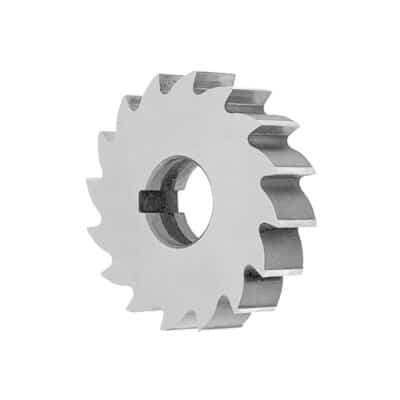
Light-duty plain milling cutters are also called fine tooth cutters. These cutters have more teeth per unit of cutter diameter and a helical angle below 25 degrees. The fine tooth cutter design means each cutter tooth takes a smaller chip, which gives me a smoother surface finish.
I pick light-duty plain milling cutters when I need a finer finish and I am only taking a small amount of material off. They run at higher cutting speeds and lower feed rates.
I use fine tooth cutters for:
- Finishing passes in the plain milling process
- Light material removal on softer materials
- Jobs where surface quality matters more than speed
Heavy-Duty Plain Milling Cutters
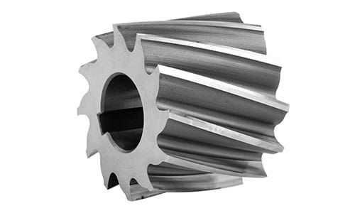
Heavy-duty plain milling cutters have fewer teeth and a steeper helical angle, typically between 25 and 45 degrees. The wider tooth spacing creates larger chip pockets, which improves chip evacuation during aggressive cuts. Some heavy-duty cutters are also designed as wider slab cutters for covering the entire surface in fewer passes.
I reach for heavy-duty cutters when I need to remove material quickly. They run at lower machining speeds and higher feed rates. The steeper helix also helps the machining edge slice into the part material more smoothly, which reduces vibration during heavy cuts.
I use heavy-duty plain milling cutters for:
- Roughing passes on large flat surfaces
- High material removal on carbon steel, cast iron, and other tough metals
- Mass production jobs where speed matters more than finish
How to Choose the Right Plain Milling Cutter
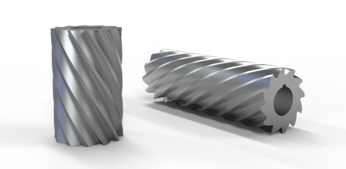
Cutter Type
My rule is simple. If I need to remove a lot of material and I do not care about the surface finish, I go heavy-duty. If I need a clean finish and I am only taking a light cut, I choose fine tooth cutters. Many jobs need both: a roughing pass with a heavy-duty cutter, then a finishing pass with a light-duty plain milling cutter.
When selecting the right plain milling cutter, I also consider cutter width and cutter diameter. Wider slab cutters cover the entire surface in one pass but need more machine power and a rigid machine setup. Narrow cutters work better on smaller milling machines or when I need to mill a specific band across a wider workpiece without covering the entire surface.
Cutter Material
Cutter material changes with the part material and the production volume.
- High-speed steel (HSS): I use HSS for softer materials like aluminum and copper, and for shorter production runs. HSS is cheaper and easier to resharpen, but the cutting edge loses its sharpness faster under heat, which increases tool wear.
- Carbide-tipped cutters: I switch to carbide tipped cutters when I am working carbon steel, stainless steel, or running long production jobs. Carbide holds its cutting edge much longer under heat and allows higher cutting speeds, which shortens cycle time. For any production plain milling process, carbide is the default.
- Indexable insert cutters: For high-volume and mass production milling operations, I use cutters with replaceable carbide inserts. When a cutting edge wears out, I rotate the insert instead of replacing the whole cutter. This keeps the machine tool running and reduces tooling cost per part.
Cutter Coatings
Coatings extend tool life and reduce tool wear, especially on harder workpiece materials.
- TiN (titanium nitride): A general-purpose coating that increases surface hardness and reduces friction on the cutting edge. Good for carbon steel and cast iron.
- TiAlN (titanium aluminum nitride): Handles higher cutting speeds and temperatures than TiN. I use it for dry machining or high-speed plain milling operations on hardened steel.
- AlCrN (aluminum chromium nitride): Excels in high-temperature applications and abrasive workpiece materials like titanium alloys. Reduces edge chipping and extends tool life significantly.
Uncoated HSS works fine for aluminum and plastics. The moment I move to steel or increase cutting speed, a coated cutter pays for itself in lower tool wear and fewer tool changes.
Cutter Design Considerations
Beyond type and material, the cutter design affects plain milling performance. Key factors include:
- Helix angle: A steeper helix produces a smoother cut but increases axial force on the milling machine spindle. I balance this against the rigidity of the setup.
- Number of teeth: More teeth (fine tooth cutters) give a better finish but generate more heat. Fewer teeth clear chips better and suit heavy roughing.
- Cutter width: Should match or slightly exceed the workpiece width. If the cutter is too narrow, I need overlapping passes, which can leave a witness mark on the flat surface.
Materials Suitable for the Plain Milling Process
The plain milling process handles a wide range of workpiece materials. The cutter material, the coating, and the cutting parameters change with the workpiece material, but the milling process itself stays the same.
- Metals: aluminum, copper, brass, carbon steel, stainless steel, tool steel, titanium, cast iron
- Plastics: nylon, acetal (POM), PVC, HDPE, PTFE
- Composites: carbon fiber, glass-filled polymers
For softer materials like aluminum and plastics, I run higher cutting speeds and lighter feed rates. For harder workpiece materials like stainless steel and titanium, I slow the cutting speed down, increase the feed per tooth, use carbide tipped cutters, and make sure coolant coverage is solid. The workpiece material is the single biggest factor in deciding every other parameter in the plain milling process.
Advantages of Plain Milling
Here is what the plain milling process does well.
High material removal rate
The cutting edges stay in contact with a large area of the workpiece at once. The rotating cutter peels material across the entire surface in each pass. That means more material comes off per pass than most other milling techniques. When I have a thick plate that needs to be brought down to size, the plain milling process gets me there fast.
Low tooling cost
Plain milling cutters are standard machine tool accessories. I do not need custom tooling, special inserts, or exotic cutter geometry. Light-duty and heavy-duty plain milling cutters cover almost every job I run, and both are easy to source and replace.
Simple setup
The plain milling process has fewer variables than slot milling, chamfering, or contour milling. Pick the right plain milling cutter, clamp the part, set the parameters, cut. A machinist who is new to milling operations can run a plain milling job safely after a short training period.
Consistent results in mass production
Because the setup is simple and the cutter geometry is stable, I get repeatable results across large batches. Dimensional consistency is strong, which matters when I am machining base plates, mounting surfaces, or reference faces for downstream milling operations.
Good surface finish with the right cutter
A fine tooth cutter with the right parameters gives me a surface finish that is ready for many end uses without secondary operations. I do not always need to follow up with grinding.
Efficient for creating flat reference surfaces
Almost every machining workflow starts with squaring up stock and creating a clean flat surface as a reference face. The plain milling process is the fastest way I know to do that on most flat surfaces.
Adapts to different workpiece materials
I have used the plain milling process on everything from soft aluminum to carbon steel to engineering plastics. The milling process adapts: I change the cutter material, the cutting speeds, and the feeds to match the workpiece material.
Disadvantages of Plain Milling
The plain milling process is not the right answer for every job. Here is where it falls short.
Limited to flat surfaces
Plain milling cuts only flat surfaces. I cannot cut slots, pockets, steps, contours, or 3D shapes with it. Unlike end milling, which can access features from multiple angles, the plain milling process only works along one cutting axis. The moment a part needs anything beyond a flat surface, I have to bring in a different milling operation.
Coarser finish than some other milling operations
The cutting edges on the periphery leave a series of small scallops across the cut. Heavy-duty cutters with fewer teeth make this worse. For reference, a face mill on the same material typically achieves Ra 0.4 to 0.8 μm, compared to Ra 0.8 to 1.6 μm for a plain milling finishing pass. If the part needs a finer finish, I follow the plain milling process with a finishing pass or grinding, which adds time.
Requires horizontal milling machines
The plain milling process runs best on horizontal milling machines with a rigid arbor. Many modern shops run mostly vertical machining centers with a vertical spindle, so if I do not have horizontal milling machines or an HMC, I cannot run the plain milling process the way it is designed to work. On a vertical milling machine, a face mill or shell mill is usually the better choice for producing a flat surface.
Vibration and chatter risks
The arbor is long and the cutter is wide, which means the setup is more prone to vibration than a short end mill on a rigid machine. Chatter leaves marks on the workpiece surface, increases tool wear, and shortens tool life. I have to pay extra attention to arbor support, workholding rigidity, and cutting parameters to keep the plain milling process stable.
Burrs form on the edges
Plain milling cuts tend to push material off the edge of the workpiece, which creates burrs. For most parts, I need a deburring step after the milling process. That is extra handling and extra time.
Heat buildup on heavy cuts
When I am removing large amounts of material with a heavy-duty cutter at high cutting speeds, heat builds up fast. Without enough coolant or proper chip evacuation, tool wear accelerates, the workpiece surface discolors, and tool life drops. On hard steels, this gets expensive quickly and can cause edge chipping on the cutter.
Plain Milling vs. End Milling vs. Other Milling Operations
These milling operations cover the majority of work in any shop. Each has a distinct strength.
| Feature | Plain Milling | Face Milling | End Milling |
| Feature | Plain Milling | Face Milling | End Milling |
| Tool axis orientation | Parallel to the flat surface | Perpendicular to the flat surface | Perpendicular to the flat surface |
| Cutting action | Peripheral (outer cutting edges) | Face (bottom cutting edges) | Both peripheral and face |
| Best for | Wide flat surfaces, stock removal | Finishing large faces, squaring ends | Slots, pockets, contours, 3D shapes |
| Typical surface finish (Ra) | 0.8 to 6.3 μm | 0.4 to 1.6 μm | 0.8 to 3.2 μm |
| Material removal rate | High | Moderate to high | Low to moderate |
| Machine type | Horizontal milling machines | Vertical or horizontal milling machines | Vertical milling machine (most common) |
| Geometric flexibility | Low (flat surfaces only) | Low to moderate | High |
| Tooling cost | Low | Moderate (insert costs) | Low to moderate |
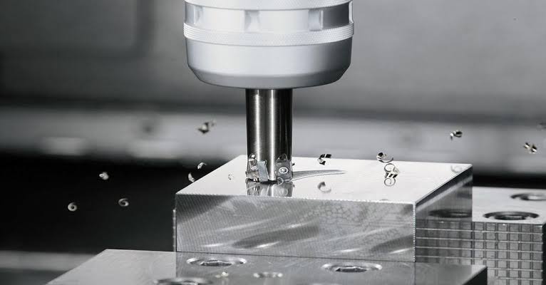
When to choose the plain milling process: Use it when you need to remove material from a wide flat surface quickly. The plain milling process excels at roughing and stock preparation on horizontal milling machines.
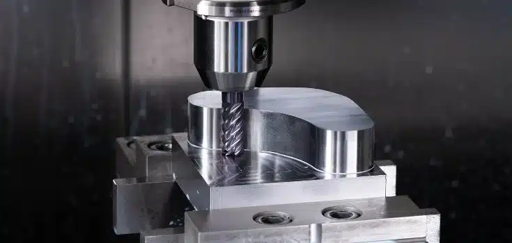
When to choose end milling: Use it when the part has pockets, slots, contours, or any geometry that requires the cutter to access features from multiple angles along different cutting axes. End milling handles complexity that the plain milling process cannot.
When to choose other milling operations: Gang milling (running multiple cutters on one arbor) handles several flat surfaces or steps in a single pass and is efficient for mass production of identical parts. Gang milling is worth considering when your part has multiple parallel flat surfaces at different heights. Straddle milling is another option for machining two parallel flat surfaces simultaneously.
In many jobs, I combine milling operations. I rough the flat surface with plain milling, finish it with a face mill, cut slots and pockets with end milling, and use a mill drill for hole-making, all in one setup on a CNC machining center.
Applications of Plain Milling
The plain milling process shows up across many industries. The jobs I see it used for most often include:
- Machining base plates, mounting surfaces, and machine bed flat surfaces
- Squaring up raw stock before secondary operations like drilling, tapping, or end milling
- Creating reference faces for inspection and downstream milling operations
- Roughing aerospace structural components like wing ribs and bulkheads
- Finishing automotive engine block flat surfaces and cylinder heads
- Preparing mold plates and die blocks for EDM or finish machining
- Producing flat surfaces on heavy equipment components such as excavator frames and gear housings
- Surfacing large weldments to bring warped faces back into tolerance
- Mass production of mounting brackets, flanges, and machine tool components that need most flat surfaces brought to spec quickly
Anywhere a job calls for a large flat surface machined across the entire surface, the plain milling process is usually in the conversation.
Common Issues and How to Improve Plain Milling Performance
I have run into the same handful of problems over the years. Here is what causes them and how I handle each one to improve plain milling performance.
Vibration and chatter. Check arbor support first. If the overarm bracket is loose or the arbor is too long for the cutter width, vibration is almost guaranteed. Reduce depth of cut, lower feed rate, or switch to a cutter with fewer teeth to reduce cutting force. A rigid machine setup is non-negotiable for good plain milling performance.
Burrs on edges. Use a sharp cutting edge, climb mill where possible, and plan for a deburring step. On softer materials like aluminum, I sometimes add a small chamfer pass at the end to knock down the burrs. A mill drill can also chamfer edges in the same setup on CNC milling machines.
Surface burn marks. Increase coolant flow, lower the cutting speed, or take a lighter cut. Burn marks usually mean the cutting edge is rubbing instead of cutting, which points to excessive tool wear or too low a feed rate.
Poor surface quality. Switch to fine tooth cutters, drop the feed rate, and verify the cutting edge is not worn. If the surface quality is still rough, check for runout on the arbor. Even 0.02 mm of runout can leave visible marks across the flat surface.
Excessive tool wear and short tool life. Match the cutter material to the workpiece material. HSS on hardened carbon steel wears out fast. Use carbide tipped cutters or a coated cutter, apply proper coolant, and keep chip loads within the recommended range for the cutter diameter and the workpiece material. Adjust cutting parameters when you notice tool wear accelerating: lower the cutting speed before the cutting edge chips.
Edge chipping on the cutter. Edge chipping usually comes from an interrupted cut, excessive cutting speed, or the wrong cutter material for the workpiece material. Reduce the cutting speed, switch to a tougher carbide grade, and make sure the machine tool is rigid enough for the depth of cut.
Uneven depth of cut across the flat surface. This usually comes from a workpiece that is not sitting flat on the table, or from table alignment issues on the milling machine. Re-indicate the workpiece and check the milling machine table for wear or debris before re-cutting.
Poor chip evacuation. On horizontal milling machines, chips usually fall away from the cutting zone by gravity. If chips are piling up and recutting, increase coolant pressure, check that the slab cutters or narrow cutters have enough tooth spacing for the depth of cut, and make sure the milling machine has a chip conveyor running.
FAQs
What is the difference between plain milling and face milling?
The plain milling process cuts with the teeth on the outer circumference of a cylindrical rotating cutter, and the cutter’s axis is parallel to the flat surface. Face milling cuts with the teeth on the bottom face of the cutter, and the tool axis is perpendicular to the workpiece surface. The plain milling process removes material faster on wide flat surfaces, while face milling produces a finer surface finish.
What surface finish can I expect from the plain milling process?
With a heavy-duty roughing cutter, expect Ra 3.2 to 6.3 μm. With fine tooth cutters and optimized cutting speed, you can reach Ra 0.8 to 1.6 μm. If you need a finer finish, follow the plain milling process with a face milling pass or grinding.
Is plain milling the same as slab milling?
Yes. Plain milling, slab milling, and surface milling all refer to the same milling process: using a cylindrical peripheral rotating cutter to machine a flat surface on horizontal milling machines.
How do I reduce chatter in the plain milling process?
Start by checking arbor rigidity and overarm support on the milling machine. Then reduce the depth of cut or lower the feed rate. If chatter persists, try narrow cutters with fewer teeth or a steeper helix angle. A rigid machine setup and proper cutter engagement also improve plain milling performance.
When should I use climb milling vs. conventional milling?
Use climb milling when the machine tool is rigid and has no backlash. It gives a better surface finish and lower tool wear. Use conventional milling on older milling machines with backlash, or when the cutting edge needs to get under a hard surface scale. For most CNC plain milling operations, climb milling is the default.
What is gang milling and how does it relate to plain milling?
Gang milling uses multiple cutters mounted together on the same arbor to machine several flat surfaces, steps, or grooves in a single pass. It is a variation of the plain milling process that is especially useful in mass production, where I need to machine multiple parallel features on every part. Gang milling reduces cycle time significantly compared to running each milling operation separately.
