

 EU
EUA CNC machine cuts only what the tooling can reach, and it charges for every extra pass. Most quote surprises and long lead times trace back to a few design choices: an internal corner too sharp for any stock cutter, a wall too thin to stay rigid, a hole deeper than a drill can reach without wandering off line. Each one quietly adds cost, lead time, or scrap risk.
Designing for machining means shaping the part around how the CNC machining process actually cuts, well before the file reaches a quote. The same function can usually be built into geometry that machines faster and holds tolerance better. This CNC machining design guide covers the design rules that carry the most weight in CNC milling and turning, each with figures you can design against.
Why Design for Machining Matters
A skilled machinist can make almost any geometry. The real question in CNC machining design is never whether a part can be cut, but what it costs to cut it. That cost is set in the CAD model, long before the job reaches the shop floor, and it runs down one chain:
Design Decision ──► Tool Access & Setups ──► Machining Time ──► Unit Cost
Four things ride on getting the geometry right during the design process:
- Cost control: Machining cost tracks cycle time and setup count. A pocket that forces a smaller cutter runs slower, a feature on a fifth face adds a setup, and an over-tight tolerance adds an inspection step. This is why two parts of the same size can price very differently.
- Manufacturability: CNC tools are rotating cutters with physical limits. They flex under load, and tool deflection grows with the tool’s aspect ratio, so sharp internal corners, thin walls, and deep narrow cavities can make a feature hard or impossible to cut cleanly.
- Quality and accuracy: Realistic tolerances and accessible geometry hold dimensional accuracy from one part to the next. Features sized to standard tools resist chatter and warping, which means better surface finish and fewer rejects.
- Lead time: Parts drawn around standard cutters, simple workholding, and single setups move through the shop without manual intervention or constant tool changes. Turnaround stays predictable across prototype batches and volume runs alike.
Catching these issues early costs almost nothing. A corner radius or wall thickness changed during design is a two-minute edit. The same change after a failed quote means a redesign loop, and after a part fails in production, scrapped material and a slipped deadline. The guidelines that follow move those decisions to where they are cheapest to make.
Key Design Guidelines for CNC Machining
The CNC machining design guidelines below turn those limits into figures you can design against. None bans a feature outright. Each names the point where a choice starts costing time, accuracy, or money. Together they form a working CNC machining design guide you can check a model against before quoting.
Part Complexity
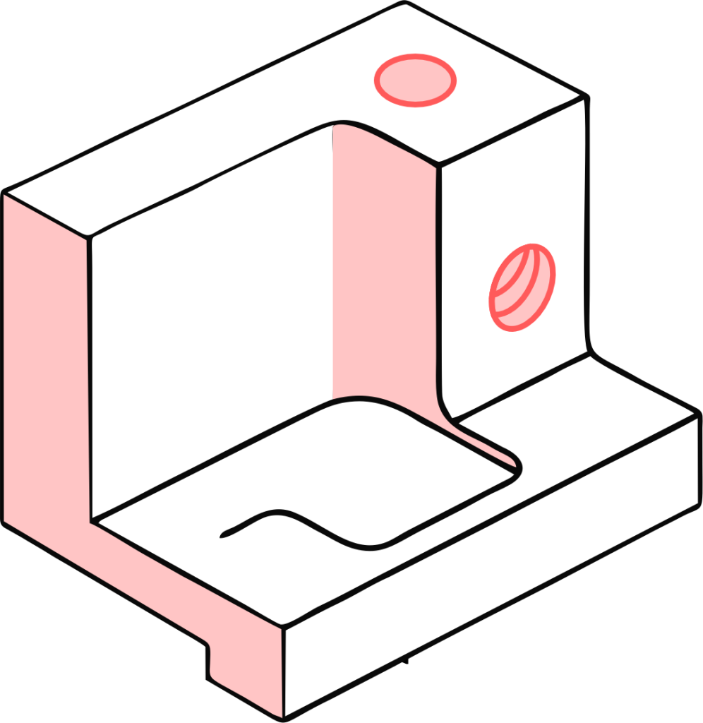
Complexity is not how the part looks, it is how hard the part geometry is to cut. It comes down to the surfaces you ask for, the number of directions the tool must approach from, and the internal features it has to reach.
- Contours and surfaces: Flat faces and vertical walls cut fast in wide passes. Curved or sloped surfaces need a ball-nose tool stepping across in small increments, so keep freeform surfaces to the features that need them and leave the rest flat.
- Setups and axes: Group features onto as few faces as possible and keep them aligned to the main X, Y, and Z axes. Aim to finish milling in 1 to 3 setups. Square angled features to an axis where you can, since compound angles force indexing or 5-axis work.
Corner Radii
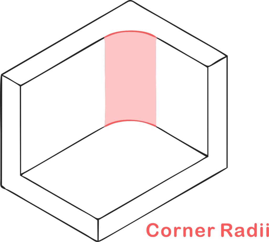
A rotating tool cannot cut sharp square corners on an inside edge, so every inside corner needs a radius.
- Internal corners: The inside radius is the fillet radius, and it should be at least the cutter radius, and as a guide at least one third of the cavity depth. A pocket corner at R3.3 for a 6 mm cutter finishes cleaner and faster than an exact R3.
- External corners: A sharp edge on an outside corner machines easily. To break it, a 45 degree chamfer is quicker and cheaper than a rounded edge. The rule: fillet internal corners, chamfer external ones.
- Floor radii: A flat end mill leaves a small radius where wall meets floor by nature. Match it to a bull-nose tool rather than forcing a sharp floor corner, which needs a second, slower machining operation.
Pockets and Cavities
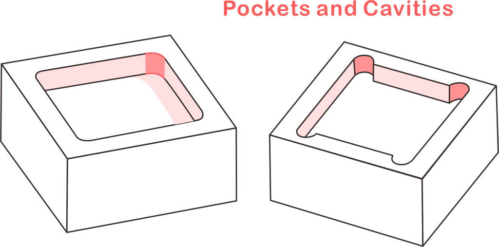
A pocket is cut by plunging an end mill and clearing material out. The deeper it goes, the longer the tool, and length is where the trouble starts.
- Depth-to-tool ratio: Keep the cavity depth within about 3 to 4 times the tool diameter, and within 4 to 5 times the pocket’s own width or length. A 12 mm cutter handles a cavity depth around 25 mm. Past that it deflects, chatters, and struggles to clear chips, which shows as a poor surface finish.
- Design around it: Widening a deep pocket lets a larger, stiffer tool reach the floor, so widen rather than narrow. Bigger internal radii let a bigger tool in. Where depth is fixed, cutting from two sides shortens the tool needed, at the cost of a setup.
Wall Thickness
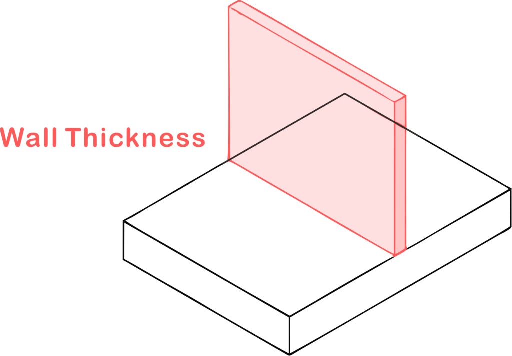
Thin walls flex and vibrate under the cutter during machining, which costs accuracy and surface finish, and past a point they crack or warp as internal stress releases. The minimum wall thickness depends on the material:
| Material | Recommended | Feasible minimum |
| Metal | 0.8 mm | 0.5 mm |
| Plastic | 1.5 mm | 1.0 mm |
- Keep walls thick enough: Plastic needs more, being less stiff and softening as it warms. The feasible column is the edge of what a shop will attempt, not a target.
- Avoid thin and long walls: A standalone wall taller than about 4 times its thickness loses surface finish. A rib, a curved profile, a cross-rib buttress, or a slight draft angle lets it run to roughly 10 times thickness. A tall thin wall with nothing behind it is the hardest case.
Holes
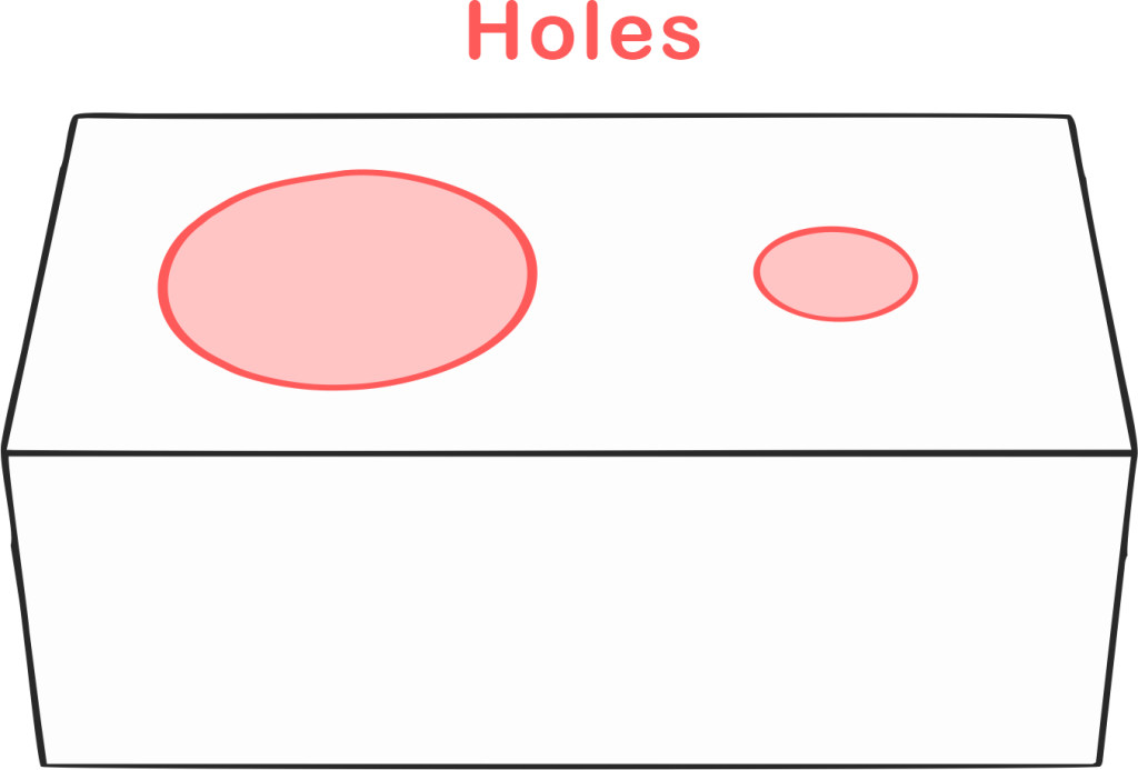
Holes machine cheaply when they follow how drills and taps work, expensively when they fight it.
- Hole diameters: Use standard drill sizes such as 3, 4, 5, 6, 8, and 10 mm. A non-standard hole diameter has to be interpolated with an end mill, which is slower. Keep a part to as few different hole sizes as possible to save tool changes.
- Hole depths: Aim for about 6 to 8 times the nominal diameter. Beyond that, chips pack the flutes and starve the tip of coolant, and the drill drifts or breaks. Deeper holes need a specialist drill or step-drilling from both sides.
- Blind holes: A standard twist drill leaves a conical bottom, not a flat one. Model the hole about 25 percent deeper than the usable length for the point and chip clearance, unless a flat bottom is genuinely required.
- Minimum diameters: Standard tooling reaches to about 2.5 mm comfortably. Below roughly 1.0 mm is micro-drilling, which breaks easily and needs high-speed spindles. Use small hole sizes only where function demands.
- Avoid partial holes: A hole breaking an edge or a cavity meets uneven material and wanders. Keep the full diameter on solid stock and the axis square to the face, or mill a small flat pad first.
Threads
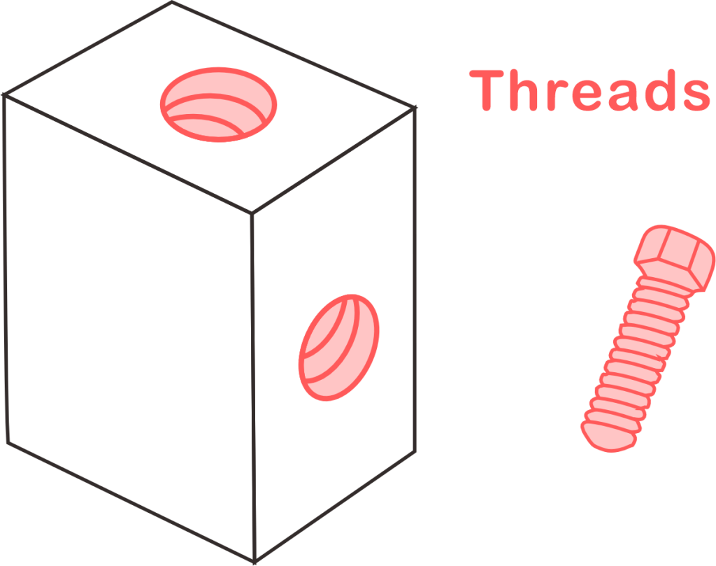
- Thread depths: Engagement of one nominal diameter suits steel and 1.5 for aluminium. Cutting deeper than about 2 times the nominal diameter adds tap-breakage risk without adding strength. In a blind hole, leave clearance past the last thread for the tap chamfer and chips.
- Thread diameters: Design threaded holes to standard profiles, ISO metric M2 to M20 or UNC/UNF. Internal threads are cut with taps, external threads with dies. Custom pitches force a special tap, and threads below about M2 turn fragile.
Tolerances
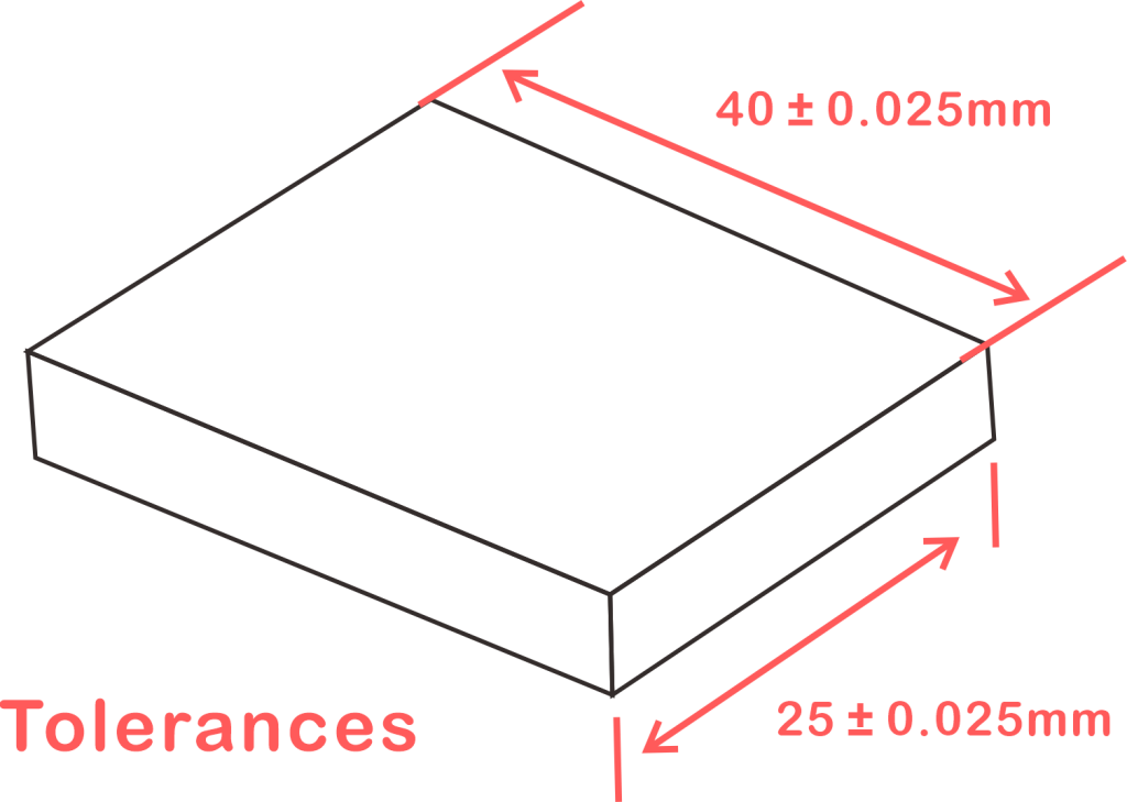
Tolerance is the band a dimension may vary within. Tighter bands cost more, in machining time and inspection both.
| Tolerance class | Range | Notes |
| Standard (metal) | ±0.1 mm (±0.005 in.) | No technical drawing needed |
| Tight (metal) | ±0.025 mm | Slower feeds, added inspection |
| Achievable limit | around ±0.010 mm | Reaming or fine finishing |
| Plastic | ±0.1 mm and looser | Moves with temperature |
- General tolerances: Left unspecified, a shop works to around ±0.1 mm, which suits most non-mating features, clearance pockets, and outer profiles at no added cost.
- Tight tolerances: Reserve tight bands for mating faces, bearing seats, and dowel-pin holes. Holding them means slower feeds, temperature control, frequent measurement, and often a reaming pass. Anything under ±0.1 mm on plastic is hard to hold. A tight tolerance has to be called out on a technical drawing, since the CAD model alone does not carry it, so every one should trace to a function in your design specifications.
Text and Lettering
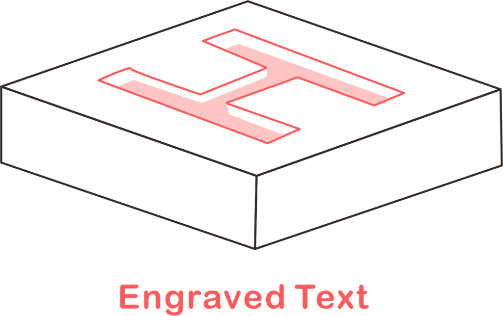
Machined text is slow, because small letters need small tools and a clean floor finish under the characters is hard to reach. Where a label can be applied another way, that is usually cheaper.
- Recessed, not raised: Recessed text clears only the letters. Raised text clears the whole surrounding face, and is normally reserved for parts going on to a mould tool.
- Font and size: Use a bold sans-serif such as Arial or Helvetica. Keep type at 20 point or larger with strokes at least 0.5 mm, cut to a shallow depth around 0.3 mm.
Undercuts
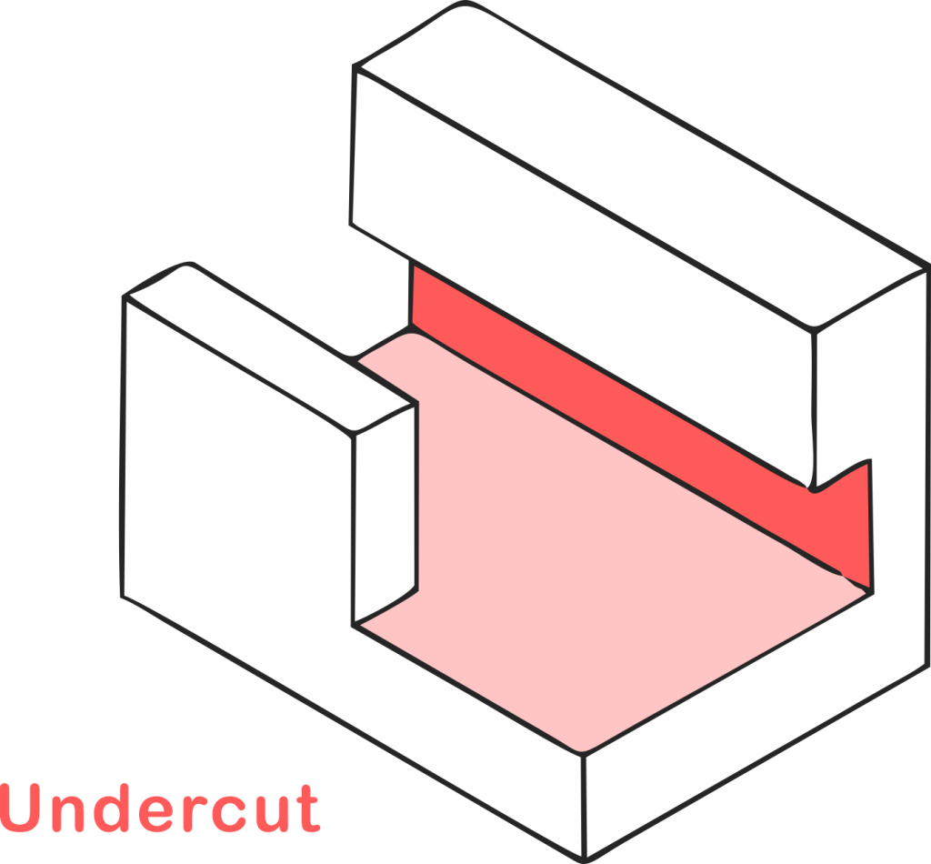
An undercut cuts back under a surface, out of reach of a tool coming straight down: an internal T-slot, a dovetail, a retaining-ring groove. A standard end mill cannot form one.
- Design them out where you can: Each undercut adds a special tool such as a T-slot, woodruff, or lollipop cutter, often an extra setup, and slower machining.
- Where one is needed: Size it to a standard undercut tool, not an arbitrary profile, and leave room to enter and clear. If it cannot be reached at all, splitting the part into two machined pieces is sometimes cheaper.
Material Selection for CNC Machining
Material choice sets a part’s strength, cutting speed, tolerance and much of its cost, so it belongs at the core of any CNC machining design guide. Start from the job: loads, temperature, and exposure to moisture, UV or chemicals. That rules most materials out before machinability decides the rest.
Machinability matters most. Soft metals like aluminium and brass cut fast and cheap, while stainless and titanium cut slowly, wear tools and cost more. A softer material that still meets the load often cuts machining time sharply, and the same applies to plastic parts.
| Material | Machinability | Notes |
| Aluminium 6061 | Excellent | Default workhorse. Light, cheap to cut, anodises well |
| Aluminium 7075 | Very good | Higher strength, for structural and aerospace parts |
| Brass | Excellent | Cuts cleanly at speed, good for fittings and electrical parts |
| Copper (C110) | Fair | High conductivity, gummy to cut, for bus bars and heat sinks |
| Mild steel (1018) | Good | Strong, low cost, needs a finish against corrosion |
| Stainless (303, 304, 316) | Fair | Corrosion-resistant but slower to cut. 303 machines easiest |
| Titanium | Poor | High strength-to-weight, slow and costly. Use only where it earns it |
| ABS, POM, Nylon | Excellent | Cheap and fast, lower stiffness. POM holds tolerance best |
| Acrylic (PMMA) | Good | Optically clear, polishes to transparency, but brittle |
| PC, PEEK | Good | Higher performance, PEEK for heat and chemicals at a premium |
Three things around the table. Alloy condition matters, so call out a temper like 6061-T6 rather than leave it to assumption. Stock size matters: size the part near an available raw material thickness or bar diameter to avoid special sourcing or wasted material. And plastics hold tolerance poorly, so for tight-tolerance machined parts, aluminium is often better and no dearer.
Finish belongs here too. If the part will get a finish such as anodising, plating, or powder coating, that shapes the metal choice, since 6061 anodises cleanly while some alloys do not.
Good CNC machining design keeps every feature within reach of standard tooling, and checking a model against this CNC design guide before requesting a quote removes most cost and lead-time surprises. A DFM review does the same automatically, flagging the features that will fight the tooling while the geometry can still move. Aria runs that check on machined parts as standard, so issues surface at the quote, not once machining is under way.
Understand CNC Capabilities and Limitations
Every guideline above reduces to three facts about the machine. Hold these and you can judge a new feature without a table.
The machine only reaches what the tool can touch
It cuts a solid block from the outside in, so a sealed cavity or a surface under an overhang cannot be machined. Picture the cutter as your finger: it runs along walls and drops into holes, but it cannot bend around a corner.
The tools are round and they flex
Every inside corner ends up with a radius, a drilled hole ends in a point not a flat floor, and a long slender tool bends under load. That single fact is behind the rules on corner radii, pocket depth, and thin walls.
Standard tooling is cheapest
Cutters come in common sizes, so a design built around them cuts straight away, while an odd radius or hole forces a special tool and added lead time.
Read against those three, the guidelines stop being a list to memorise and become something you can reason from.
FAQs
Q: What is CNC milling?
A: A subtractive machining process where a spinning cutter removes material from a fixed block as the tool moves along three or more axes. It cuts flat faces, pockets, slots, and holes, and suits most non-cylindrical CNC milled parts.
Q: How do I design CNC machined parts?
A: Design around the tool. Use standard hole and thread sizes, radius internal corners to a stock cutter, keep walls above 0.8 mm metal or 1.5 mm plastic, limit cavity depth to about 3 to 4 times the tool diameter, group features onto few faces, and tighten tolerances only where parts mate.
Q: How can I reduce CNC machining costs?
A: Cut machining effort. Use a softer material like aluminium, keep tolerances loose except where needed, match hole sizes and radii to standard tools, reduce setups, avoid deep pockets and thin walls, and skip machined text and undercuts where possible.
Q: What is the best design software for CNC machining?
A: SolidWorks, Autodesk Fusion, Autodesk Inventor, PTC Creo, and Siemens NX are all widely used. Any of them works if it exports a clean CAD file in STEP or IGES, which is what the shop needs.
Q: What are the common types of cutting tools?
A: Flat, bull-nose, and ball end mills for pockets, floors, and curved surfaces; drills for holes; taps for threads; face mills for large flat surfaces; slot and undercut cutters for grooves and undercuts, each chosen to match the feature, whether flat or part of a cylindrical shape.
Q: What file format should I submit for CNC machining?
A: STEP (.step / .stp) is preferred, IGES (.iges) is also accepted. Both carry full 3D geometry. Add a 2D technical drawing (PDF) only when tolerances, threads, or critical dimensions need calling out.
