

 EU
Gears transmit torque and control motion in nearly every machine, so the way they are made directly shapes performance, noise, and service life. For mechanical engineers, product designers, and purchasing managers, choosing the right gear manufacturing process requires a clear grasp of shop floor practices. This guide breaks down gear production by examining core machining methods, available gear types, and reliable materials.
What is Gear Machining?
Gear machining refers to a precision manufacturing process that cuts, shapes, and finishes metal or plastic gear blanks into functional gears. The goal is smooth torque transmission, controlled backlash, and reliable load bearing.
Gear machining is not a single operation. It is a combination of operations that shape, refine, and correct tooth geometry until the gear performs as intended in its final assembly. A typical sequence goes from blank preparation to tooth cutting, optional heat treatment, finishing, and inspection.
The Main Steps of Gear Machining process
Gear machining follows a defined flow of five main steps: blank preparation, tooth cutting, heat treatment, finishing, and inspection. But the flow is not rigid. The order of operations and the decisions made at each stage directly affect accuracy, cost, and whether the gear performs as intended once it is in service.
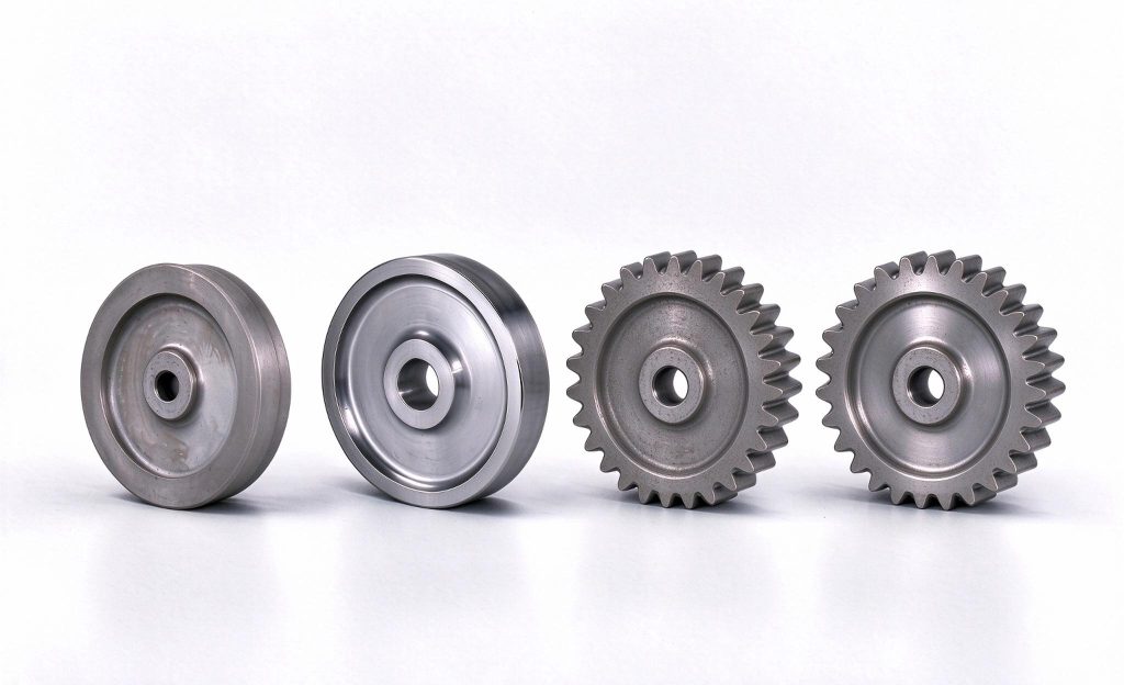
Blank Preparation
Every gear starts as a gear blank. This is a round piece of raw material, formed to a rough size before any gear teeth are cut. Steel, aluminum, and powder metallurgy alloys are the most common choices. The material depends on the load, speed, and cost target of the gear.
Three primary dimensions must be closely controlled during this stage. These dimensions are the precise outer diameter, the face width and bore specification. Tight process control over these initial parameters keeps dimensional errors from carrying into later stages of the machining process.
Gear Teeth Cutting
Once the blank is ready, the gear cutting process moves into primary tooth generation. The cutter removes material from the outer rim. It cuts one tooth space at a time, working around the full circumference to form the gear teeth. This rough cutting operation focuses on achieving consistent tooth spacing and a repeatable base gear profile rather than a final surface finish.
The chosen gear cutting method depends on gear type, production volume, and geometry. Common choices include gear hobbing, gear shaping on gear shapers, and broaching. In many workflows, cutting leaves a small amount of stock on the tooth flanks. Later steps use this remaining material to correct heat treatment distortion and reach final accuracy.
Heat Treatment (Optional)
If the gear requires heat treatment, it usually follows the first cutting pass. Gears that carry heavy loads, run at high speeds, or must endure millions of operating cycles require this step.
While heat treatment hardens the surface of the gear teeth and improves wear resistance, it also induces part distortion. This dimensional shift makes subsequent finishing operations necessary to restore required accuracy and tight tolerances.
Refinement and Finishing
Finishing operations correct distortion from heat treatment and improve tooth profile accuracy. They also achieve the required surface smoothness while maintaining tight tolerances. Primary methods include gear shaving, gear honing, gear grinding: gear lapping, and gear burnishing. In precision gear machining, this step removes minor tooth errors, reduces operational noise, and corrects heat treatment distortion.
Gear Shaving: A pre-heat treatment process that uses a serrated cutter to shear tiny metal chips from soft tooth flanks, improving gear geometry and quiet running.
Gear Honing: A post-heat treatment finishing method that uses an abrasive impregnated tool to correct minor tooth errors, improve surface finish, and reduce gear noise.
Gear Grinding: An accurate post-heat treatment method using abrasive grinding wheels to remove distortion, achieving tight tolerances and smooth surface profiles on hardened gears.
Gear Lapping: A process where two gears mesh together under light load with an abrasive compound between them, smoothing out surface irregularities for optimal mating performance.
Gear Burnishing: A chipless cold-working process where hardened master gears press against the target gear, smoothing out surface peaks through plastic deformation without cutting material.
Inspection and Verification
Inspection closes the gear machining process. These checks evaluate critical parameters of the gear teeth, including tooth profile, lead, pitch, and runout, against strict engineering specifications.This step confirms more than size. It shows whether the gear will transmit load smoothly in real operating conditions.
A common mistake is to check only the final inspection report and skip the datums between operations. A better approach is to set checkpoints at each stage. At the blank stage, measure face runout, bore size, and wall thickness variation. After heat treatment, measure the distortion pattern and use it to adjust grinding stock. On the finished gear, check profile, lead, and cumulative pitch. Moving checks earlier costs less than full inspection of finished parts.
What Are the Different Gear Machining Methods?
Gear Machining methods fall into three groups: gear generation, gear form cutting, and gear forming. Gear generation and gear form cutting remove material from a blank, mostly with conventional methods. Gear forming shapes the gear without cutting it from solid stock. The common gear cutting processes differ in speed, accuracy, and the gear types they can handle.
Gear Generation
Gear generation cuts teeth by recreating the timed meshing action between the cutter and gear blank. Both the cutter and the blank move in synchronized relative motion, much like two meshing gears that transfer rotational motion at a fixed ratio. Instead of directly copying the tool shape, the tooth profile forms incrementally along the cutter’s path. This allows a single tool to produce gears with accurate involute profiles across different tooth counts, provided the module and pressure angle match.
Gear Shaping
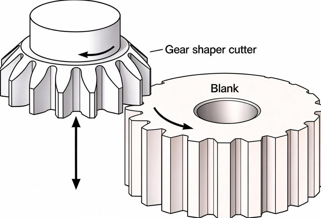
Gear shaping uses a gear-shaped cutter that moves in vertical reciprocating strokes while rotating synchronously with the gear blank. The cutter feeds in to full depth first. Then the cutter and blank rotate slowly together to generate the full tooth geometry.
Unlike gear hobbing, gear shaping works on internal gears, because the cutter strokes along the gear axis and needs little overrun space. Gear shapers can cut internal and external gears, cluster gears, and gears with tight shoulders. Gear shaping also handles spur gears, helical gears, splines, and ratchets in automated batch runs.
Gear Hobbing
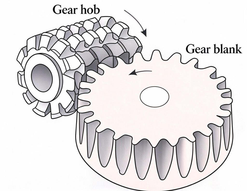
Gear hobbing utilizes a cylindrical cutter called a hob, which features thread-like cutting edges around its circumference. The hob rotates around its own axis in continuous synchronization with the gear blank, feeding across the face width. Well-designed hobs and high quality cutting tools ensure fast cycles and high accuracy. Because cutting is continuous, gear hobbing is faster than gear shaping and suits mass production.
Gear hobbing is the most common method for cutting external gear teeth, including spur gears, helical gears, worm wheels, cycloidal gears, and sprockets. However, because the hob operates on the exterior boundary, it works on external gears only and cannot cut internal gears.
Sunderland Method
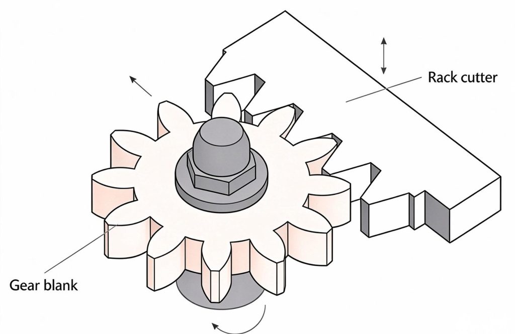
The Sunderland method uses a rack-shaped cutter with precise rake and clearance angles to generate teeth through a rolling action like that of a rack and pinion system. As the cutter strokes across the face, the gear blank rolls past it as if meshing directly with a rack, generating uniform involute profiles. Theoretically, all gears cut with the same rack cutter will mesh perfectly with each other. This method excels at producing high-precision spur gears, helical gears, and especially double helical gears (also called herringbone gears), for medium-to-large volume gear production.
Gear Form Cutting
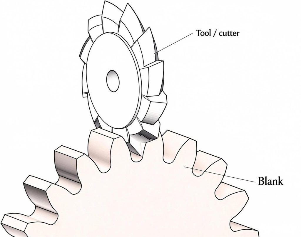
Gear form cutting relies on a cutter whose profile directly matches the exact shape of the tooth space. Instead of using complex relative roll rolling motions to generate the profile, the tool simply replicates its own geometry into the material to produce individual tooth spaces.
Because the cutter shape sets the tooth shape, a change in tooth count or module usually calls for a different cutter. Form cutting is generally slower than generation. It suits low volumes, prototypes, repairs, and gears that are too large or too unusual for other methods.
Milling
Milling uses a rotating form cutter (such as a disc or end mill) to cut one tooth space at a time. After each space is machined, the gear blank indexes to the next position. In modern shops this is typically done on CNC milling machines that follow programmed toolpaths. It is commonly used for custom, low-volume, or large-module gears, as well as prototype development where making a dedicated hob is not cost-effective. It is usually lower than that of hobbing or shaping.
Broaching
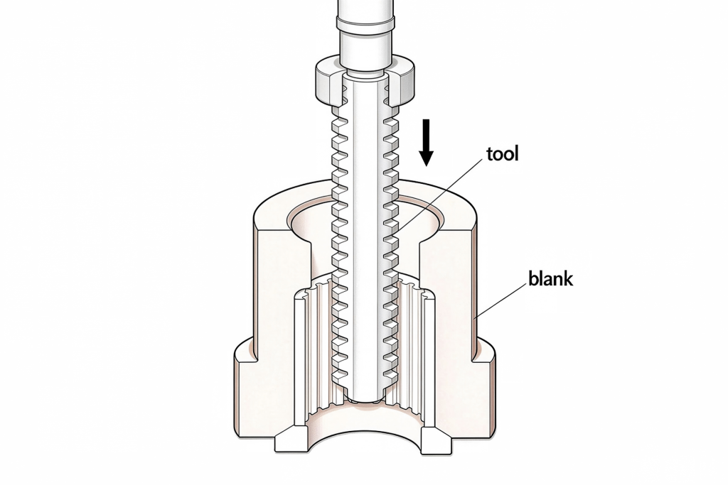
Broaching uses a long, multi-toothed tool that pushes or pulls through a pre-drilled hole or across a surface. Each successive tooth on the tool is slightly larger, cutting the entire profile in a single linear pass. This method is exceptionally fast and is widely used for cutting internal gears, splines, and keyways in high-volume production.
Shaping / Planing / Slotting
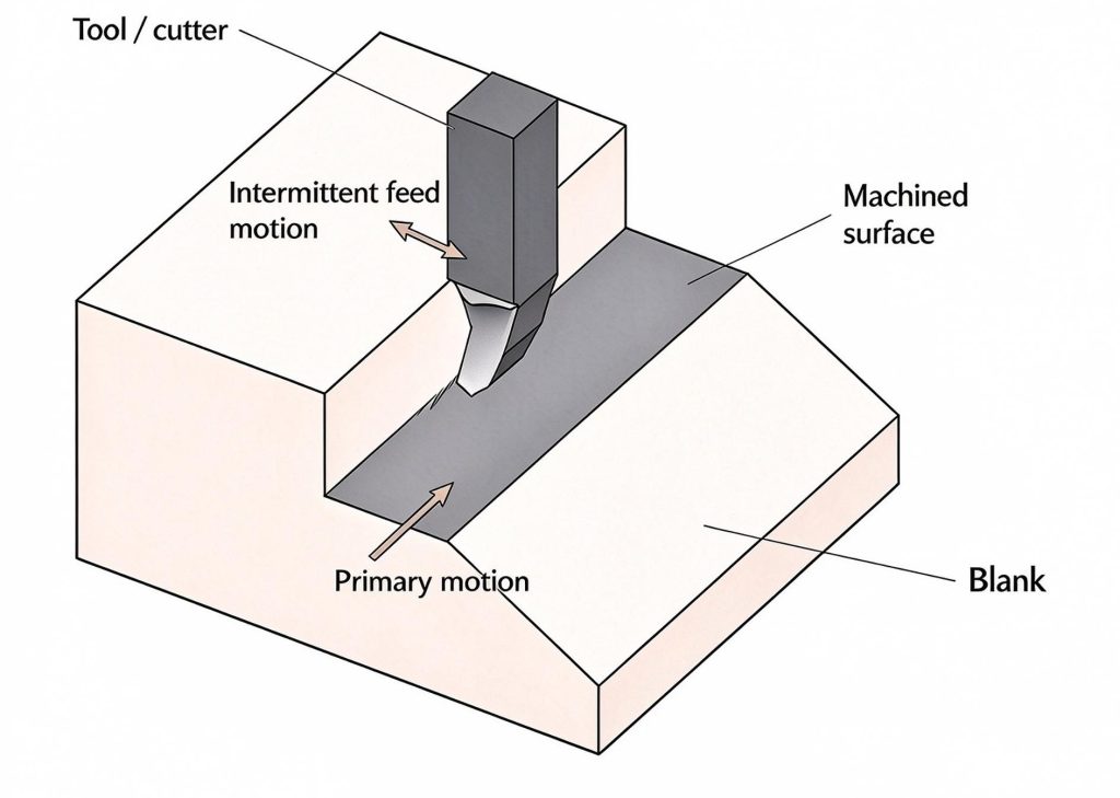
Shaping, planing, and slotting utilize single-point cutting tools that move in linear reciprocating strokes to carve out tooth profiles. Planing is often used for very large gears or bevel gears, while slotting and vertical shaping excel at cutting internal features, keyways, or specialized teeth where rotating cutters cannot fit.
Electrical discharge Machining (EDM)
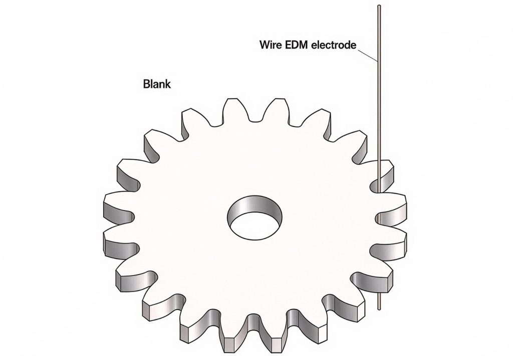
EDM is a non-traditional manufacturing process that removes material using thermal sparks between an electrode and the conductive gear blank. Because it involves no physical cutting forces, EDM can cut hardened material without added distortion. For engineers evaluating when to apply this process versus conventional CNC cutting, understanding EDM machining, how it works, and its main types helps in selecting the right approach. Wire EDM is the most widely used EDM method for gear cutting. A dedicated overview of wire EDM cutting processes, advantages, and applications shows why it is favored for intricate gear geometries. It handles internal gears, small precision gears, and profiles that conventional tools cannot reach. The process is slow and costs more per part, so it is mostly used for prototypes, tooling, and low-volume precision work.
Gear Forming
Gear forming processes create gear shapes by pouring, pressing, rolling, or printing material into a near-net or final geometry. These methods bypass traditional chip-making cuts, offering high efficiency for specific materials and production scales.
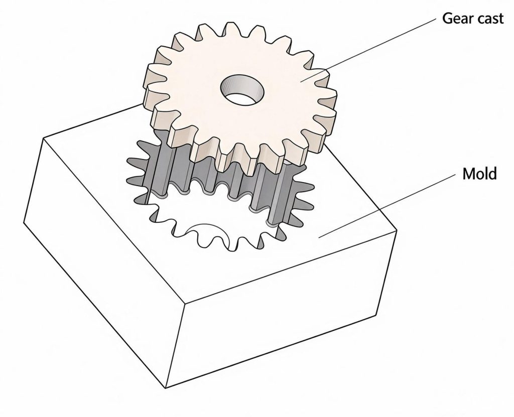
Casting
Casting pours molten metal into a mold cavity shaped like the target gear. As the metal cools and solidifies, it takes on the gear profile. This method is ideal for producing very large gears, heavy industrial components, and cost-effective cast iron or steel gears used in mining machinery, agricultural equipment, and heavy-duty drives where tight tolerances are achieved through secondary machining.
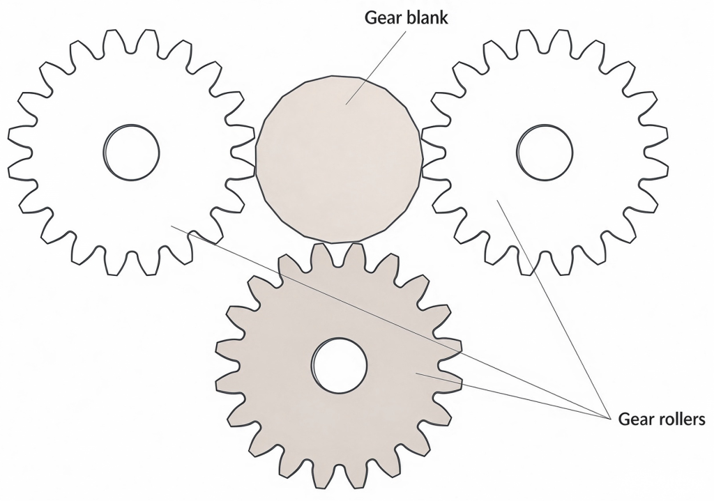
Rolling
Gear rolling uses hardened master dies pressed against a rotating metal blank under high pressure. The pressure causes the metal to flow plastically into the die cavities, forming teeth without cutting chips. This cold or warm working process produces high-strength external spur and helical gears with superior surface finish and grain structure, commonly applied in automotive transmissions and mass-produced drivetrains.
Powder Metallurgy
Powder metallurgy compacts fine metal powder inside a precision die under high pressure, followed by a heating process called sintering to fuse the particles together. This method creates near-net-shape small-to-medium spur gears, helical gears, and complex multi-level components. It is widely used for high-volume, cost-sensitive applications like power tools, automotive oil pumps, and home appliances.
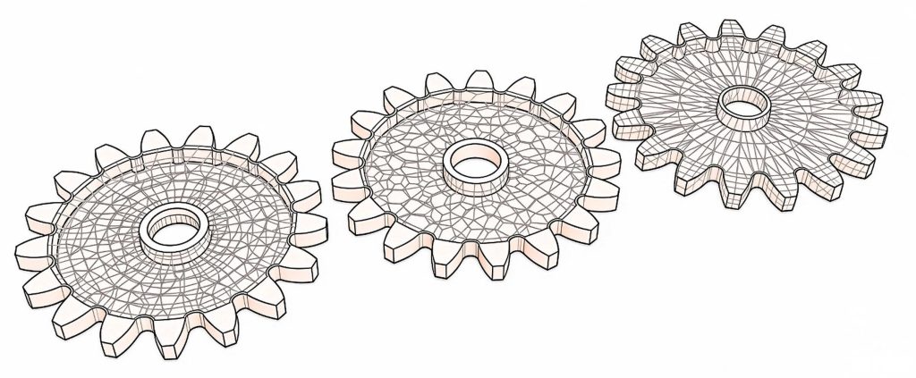
3D Printing
3D printing, or additive manufacturing, builds gears layer by layer from metal powders or polymer filaments using digital CAD models. Techniques like selective laser melting allow for complex internal geometries, weight-reducing lattice structures, and custom designs without tooling costs. It is primarily applied in aerospace components, rapid prototyping, and specialized low-volume industrial machinery.
Why Does Gear Machining Accuracy Vary?
In precision gear machining, gear accuracy rarely degrades in a single step. Small variations from tools, machines, and heat treatment accumulate throughout the gear manufacturing processes, driven primarily by four main factors.
Datum Consistency
The blank stage demands very high accuracy, and it must set one consistent datum for every later operation. Three points matter most.
- Machine the end face and bore in one setup. Two setups turn face runout into lead error.
- Keep the bore and tooth tips concentric. Off-center parts give uneven tooth thickness.
- Control clamping force. Thin-wall gears spring back to an oval shape once released.
Cutting Tool Wear and Geometry
Dull tools or worn edges alter the cut, causing the tooth profile to drift. Even small profile deviations affect contact ratio, noise, and load concentration. Four tool-related problems cause most of the drift.
- Flank wear on the hob shifts the cutting edge. Tooth thickness changes from the first part to the last.
- Chipped edges and built-up material leave a rougher tooth surface.
- A wrong rake angle or a poorly reground tool copies its errors into every tooth.
- Rising cutting force pushes the tool and blank out of position. This adds profile and lead errors.
Control tool wear and geometry with these steps.
- Set tool life limits by part count or cutting time.
- Inspect cutting edges on a schedule.
- Shift the hob along its axis to spread wear.
- Check the first part after every tool change or regrind.
Machine Tool Rigidity and Condition
Low rigidity or worn machine axes introduce vibration and chatter. This mechanical play ruins the surface finish and degrades tooth spacing, which requires rigid setups and routine maintenance to control.
Heat Treatment and Distortion
Carburizing gives high hardness and wear resistance, but distorts the gear noticeably. Induction hardening distorts less and suits larger modules. Nitriding distorts least, but its hardened layer is thin and limits load capacity. The choice sets the grinding stock left before grinding.
Quick Comparison Table
| Types of Gears | Machining Methods | Materials | Applications |
|---|---|---|---|
| Spur Gears | Hobbing, Shaping, Milling | Steel, Cast Iron, Brass, Engineering Plastics | Industrial Machinery, Precision Equipment |
| Helical Gears | Hobbing, Shaping | Alloy Steel, Cast Iron | Automotive Industry, Industrial Machinery |
| Herringbone Gears | Sunderland Method, Milling | Heavy-duty Alloy Steel | Heavy Industrial Machinery |
| Internal Gears | Shaping, Broaching, Wire EDM | Steel, Cast Iron, Powder Metallurgy | Automotive Industry, Robotics |
| Rack and Pinion | Milling (Rack), Hobbing (Pinion) | Carbon Steel, Alloy Steel, Nylon | Automotive Industry, Precision Equipment, Robotics |
| Straight Bevel Gears | Planing, Milling | Steel, Brass, Cast Iron | Industrial Machinery, Precision Equipment |
| Spiral Bevel Gears | Face Milling or Face Hobbing, then Lapping or Grinding | Case-hardened Alloy Steel | Automotive Industry, Aerospace |
| Worm Gears | Hobbing (Wheel), Milling or Turning (Worm) | Bronze (Wheel) + Steel (Worm) | Industrial Machinery, Robotics |
| Hypoid Gears | Face Milling or Face Hobbing, then Lapping or Grinding | High-strength Alloy Steel | Automotive Industry, Industrial Machinery |
Types of Machined Gears
Gears are grouped by the position of their shafts and the shape of their teeth. Each type suits a different motion and load. The sections below cover the nine most common types.
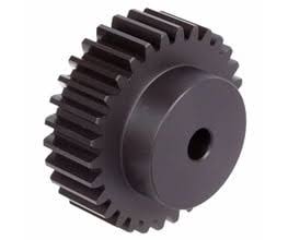
Spur Gears
Spur gears feature straight teeth parallel to the axis of rotation, making them simple to manufacture and efficient for parallel shaft drives. However, they can be noisy at high speeds. They are commonly made from steel, brass, or engineering plastics and find applications in clocks, washing machines, and basic pumps.
Helical Gears
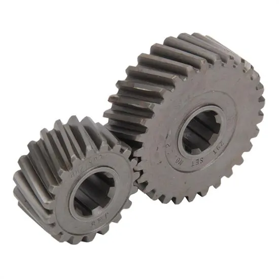
Helical gears have teeth cut at an angle to the shaft axis. The teeth engage gradually, so they run smoother and quieter than spur gears and carry more load. They create axial thrust that the bearings must handle. They are usually made from steel. Common uses are automotive transmissions and industrial gearboxes.
Herringbone Gears
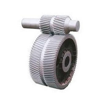
Herringbone gears have two sets of helical teeth in opposite directions, forming a V shape. The opposing angles cancel axial thrust. They handle high loads smoothly but cost more to cut. Steel is the usual material. They appear in heavy industrial drives, mining equipment, and marine propulsion.
Internal Gears
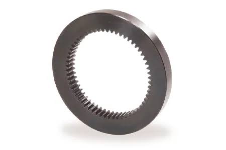
Internal gears have teeth cut on the inner surface of a cylinder, allowing them to mesh with external gears in compact spaces. They are typically fabricated from steel, cast iron, or powdered metal and are heavily utilized in planetary gear sets and automatic transmissions.
Rack and Pinion
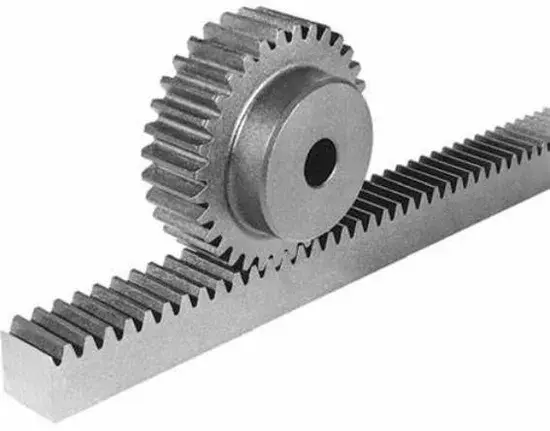
A rack is a straight bar with teeth along its length. It meshes with a small round gear called the pinion. The pair turns rotary motion into linear motion. Both parts are usually steel. Typical uses are steering systems, CNC machine axes, and sliding doors.
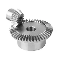
Straight Bevel Gears
Straight bevel gears feature conical blanks with straight teeth, designed to transmit power between intersecting shafts at an angle, usually ninety degrees. They are often made from steel, brass, or cast iron and are used in hand drills, differential mechanisms, and basic mechanical drives.
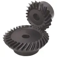
Spiral Bevel Gears
Spiral bevel gears have curved, angled teeth on a cone-shaped body. The teeth engage gradually, so they run quieter and carry more load than straight bevel gears. They suit high speeds. They are made from hardened steel and are used in helicopters, vehicle drivetrains, and heavy machinery.
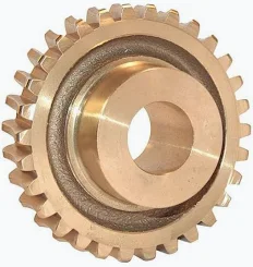
Worm Gears
Worm gears consist of a screw meshing with a large gear, providing high gear ratios and self-locking capabilities in perpendicular, non-intersecting shaft setups. They are typically built using a steel worm paired with a bronze wheel and are found in conveyor systems, lifts, and winches.
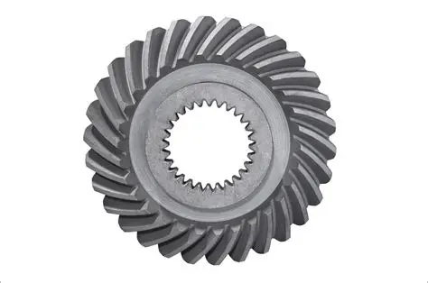
Hypoid Gears
Hypoid gears look like spiral bevel gears, but the shaft axes are offset and do not intersect. The offset allows a larger pinion, higher torque, and smooth, quiet running. Sliding contact calls for special lubricant. They are made from hardened steel and are widely used in rear axle drives of cars and trucks.
Materials for Gear Machining
Material choice sets the strength, noise level, weight, and cost of a gear. Four material groups cover most machined gears.
Steel
Steel is the default choice for high-strength gears such as helical, bevel, and hypoid gears. It offers excellent durability and wear resistance, especially after heat treatment.
Cast Iron
Cast iron is durable, cost-effective, and wear resistant. It suits gears that need good machinability but not high strength.
Bronze
Bronze has low friction and resists corrosion. It is often used for worm wheels.
Engineering Plastics
Engineering plastics such as nylon and acetal are light and quiet. They suit lightweight, low-load gears.
Applications of Gear Machining
Industrial Machinery
Transmit high torque and adjust rotational speeds in heavy equipment such as conveyors, compressors, and machine tools.
Automotive industry
Enable smooth power transfer and torque conversion across engines, transmissions, and differentials.
Aerospace
Drive flight controls, actuators, and engine accessory systems under extreme loads with high precision and low weight.
Precision Equipment
Deliver accurate indexing and smooth motion with minimal backlash in medical devices, optical tools, and measuring instruments.
Robotics
Provide exact positioning, high torque density, and smooth movement for robotic joints and automated manipulator arms.
Need machined gears for your next project? Send your drawings and requirements to Aria Manufacturing at madearia.com, and get a quote with feedback on manufacturability.
