

 EU
EUMost precision metal and plastic parts inside a machine, a vehicle, or a medical device were shaped by removing material, not adding it. CNC technology is the process behind a large share of them. Computer-controlled machines spin a rotating cutter that cuts away everything that isn’t the part, turning a solid block into a finished component with tight tolerances and repeatable results.
As a versatile manufacturing technology, CNC milling shapes a wider range of parts than almost any other machining technology. This guide covers how it works, the machines, operations, and materials involved, where it fits in production, and how to design parts that mill cleanly.
What Is CNC Milling?
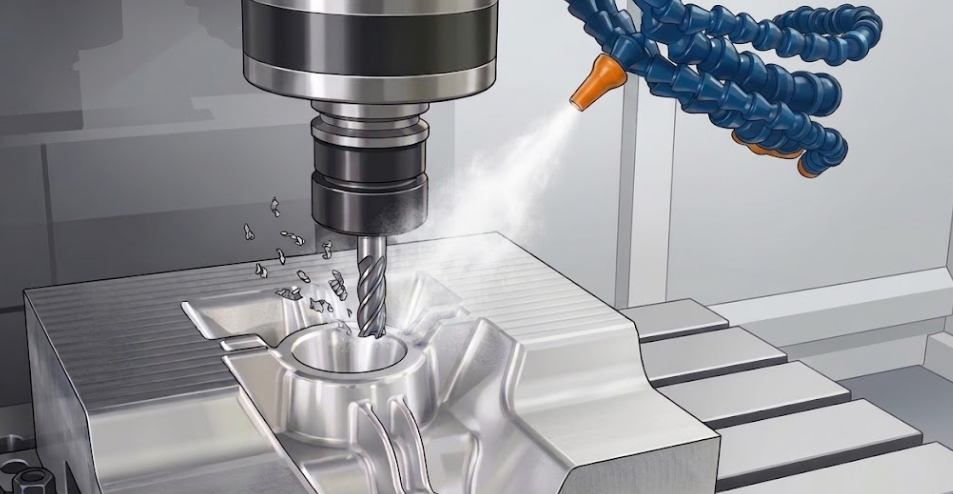
CNC milling is a subtractive manufacturing process. A rotating multi-point cutting tool removes material from a solid block, called the workpiece, until what remains is the finished part. CNC stands for Computer Numerical Control, which means a computer directs the tool’s movement and spindle speed through a program rather than a human turning handwheels. This is the difference from manual milling, where results depend on an operator’s skill. A program sets tool position, speed, and feed rate to fractions of a millimetre and repeats it every cycle, so the first unit and the five-hundredth match.
CNC milling sits inside the wider family of CNC machining, which runs various machine tools alongside the mill, including those for CNC turning, drilling, and routing.The clearest way to separate milling from turning is by what moves. In turning, the workpiece spins on a lathe while a single-point tool stays fixed, which suits round parts.
In milling, the workpiece stays clamped while the cutting tool spins and travels along several axes. That makes milling the process for parts with flat faces, pockets, slots, holes, and complex surfaces, most parts that are not simply round. Among machine tools, the mill is the one built to reach these shapes across various materials, from metals to engineering plastics.
How Does the CNC Machining Process Work?
The CNC machining process turns a 3D model into a physical part through five steps. The milling process itself is only step four; the stages around it decide whether the part comes out right. Each step affects part quality, lead time, and cost, but the first two carry the most weight. A part designed and programmed well runs cleanly. Problems built into the model reappear at every stage after.
Creating a CAD File
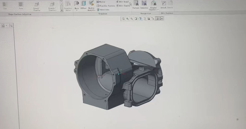
The part starts as a 3D model in CAD (computer-aided design) software such as SolidWorks, Fusion 360, or Inventor. The designer sets every dimension and tolerance and applies design for manufacturing rules here. This is where machinability is decided, long before any metal is cut. The finished model exports as a neutral file, usually STEP or IGES.
Programming (CAM)
The CAD file imports into CAM software (computer-aided manufacturing). A programmer sets the raw block size, defines the coordinate system, and assigns a cutting tool to each feature. The CAM software then generates the toolpaths and outputs the CNC program as G-code, the machine language that controls axis movement, spindle speed, feed rate, and coolant flow.
Setting Up the Machine
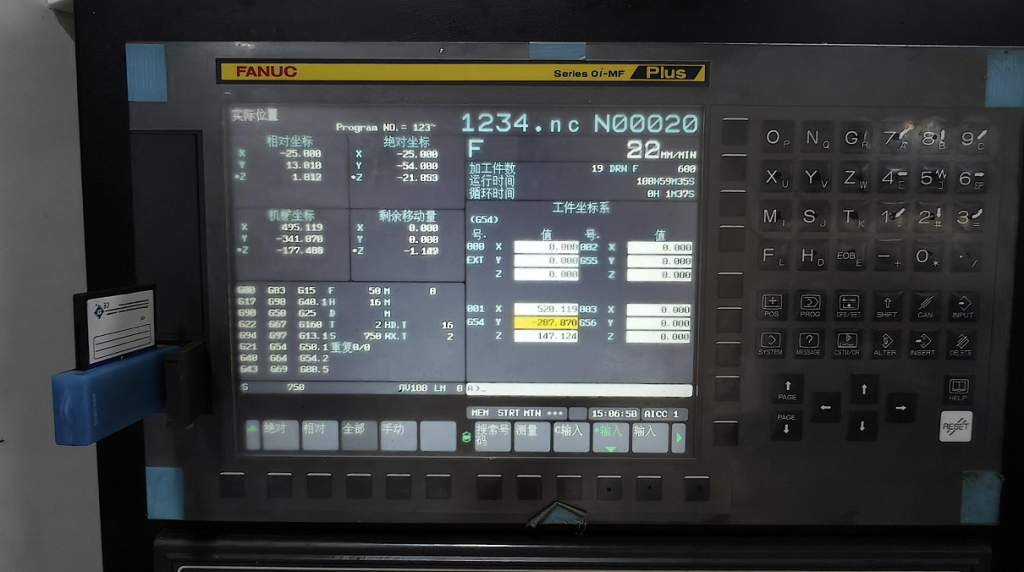
A machinist prepares the physical machine before cutting. The raw stock is mounted in a vice, fixture, or vacuum bed on the table. The right end mills, drills, and taps go into the tool carousel. Using the machine interface, the operator then measures tool offsets and sets the zero point on the stock with an indicator or touch probe. Setup is where accuracy is won or lost, since a workpiece that shifts or a wrong zero ruins the part.
Machines with automatic tool changers pull each end mill or drill from the carousel as the program calls for it, so one setup can run many tools in sequence.
Running the Milling Cycle
With the G-code loaded and the doors closed, the operator starts the cycle. The spindle spins the cutter at high speeds, thousands of revolutions per minute, while coolant floods or mists the cutting zone to control heat and clear chips. The tool follows the programmed path, removing material in passes until the geometry matches the model. Once running, the cycle needs little intervention unless a problem shows.
Inspection and Post Processing
The finished part is unclamped and deburred to remove sharp edges. Technicians then measure key dimensions with callipers, micrometers, or a CMM to check it against the drawing. Parts may go on to secondary operations such as bead blasting, anodising, or heat treatment before delivery.
Different Types of CNC Milling Machines
Milling machines are grouped by how many axes the tool and workpiece can move along. More axes mean more angles the cutter reaches in one setup, which decides both the complexity a machine handles and what it costs to run.
Horizontal and Vertical Milling Machines
Before counting axes, milling machines split into two builds by spindle axis orientation. A vertical milling machine holds the spindle upright, with the cutting tool pointing down at a stationary workpiece clamped to the table. It is the more common build and suits flat surfaces, pockets, and general work.
A horizontal milling machine mounts the spindle sideways, which clears chips better on deep cuts and handles heavier stock removal. Horizontal mills built for production are often called horizontal machining centres. Both builds come in 3-axis, 4-axis, and 5-axis configurations.
3-Axis CNC Milling Machines
The tool moves along three linear axes, X, Y, and Z, while the workpiece stays fixed. This covers most parts with flat faces, pockets, slots, and holes cut from the top. 3-axis machines are the industry workhorses: cheaper, simpler to program, and the default for straightforward geometry. The limit is reach. Any face the tool cannot get to from above means unclamping and re-fixturing the part, which adds labour and a small alignment error each time.
4-Axis CNC Milling Machines
A fourth axis adds rotation around the X-axis, turning the workpiece to a new face without a manual re-setup. This suits helical grooves, splines, cams, and off-centre holes on shafts or blocks. One setup does the work of several on a 3-axis machine, and skipping the re-fixturing keeps features better aligned.
5-Axis CNC Milling Machines
Two rotational axes join the three linear ones, the X, Y, and Z axes, letting the tool reach the part from almost any direction. It runs in two modes.
5-axis indexed (3+2): The part tilts to a fixed angle, the rotary axes lock, then the tool cuts in standard 3-axis motion. This reaches five sides in one setup and handles most parts that just need machining at several angles.
Continuous 5-axis: All five axes move at once, holding the tool at a constant angle to a curved surface. This is what turbine blades, impellers, complex moulds, and contoured implants demand. The part is cut in one setup, so errors do not stack up, and shorter, stiffer tools give a better finish.
Types of CNC Milling Operations
A milling operation is a specific way the milling cutter meets the material. Because milling is such a versatile manufacturing process, a single part usually combines several of them.
Face Milling
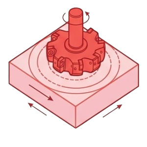
The tool axis sits perpendicular to the surface, and a large milling cutter fitted with carbide inserts removes material with its flat end. It clears large flat surfaces fast and brings a part to a precise, smooth stock height. This is the usual first step on a raw block.
End Milling
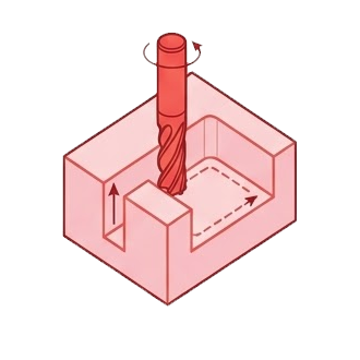
The cutter cuts on both its end and its sides, which makes it the most versatile operation of all. It produces most pockets, slots, steps, and internal shapes on a typical part. The tool can plunge straight down or ramp in on a helical path to start a cut.
Slot Milling
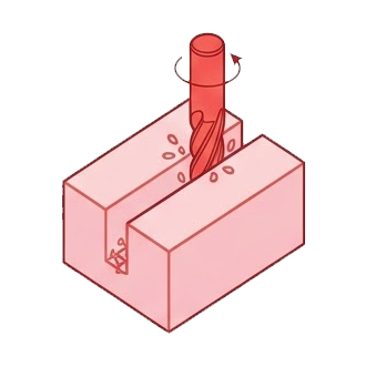
A cutter matched to the slot width cuts channels, keyways, and grooves to a set depth. Full-width slotting loads both sides of the tool at once, so feed and chip clearance need care to avoid deflection or breakage.
Pocket Milling
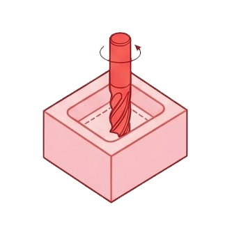
The tool clears an enclosed cavity down to a flat floor, leaving walls around it. Material comes out in progressive passes. It is a common way to cut weight out of structural parts while keeping their outer shape.
Peripheral Milling
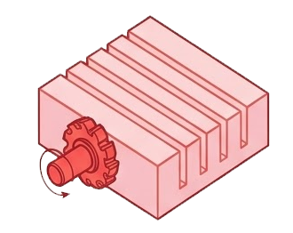
Peripheral milling, also known as plain milling or slab milling, runs the tool axis parallel to the surface so the side teeth do the cutting. It removes stock across wide flat faces and along deep vertical side walls.
Profile Milling
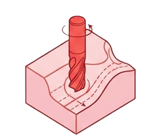
The tool follows the outer or inner contour of a part, cutting along its outline with the side of the cutter to shape curved, angled, or irregular edges. It runs in stepped passes for 2D profiles or as a continuous path for 3D contoured surfaces, and is often the operation that brings a part to its final shape and clean edge definition after roughing.
Angular Milling
The cutter is set at an angle to the workpiece to cut surfaces that are neither flat nor square to the spindle. This produces chamfers, dovetails, bevels, and angled grooves.
Beyond these, several operations handle specific features:
- Thread milling
- Gear milling
- Helical milling
- Straddle milling
- gang milling
CNC Milling Materials Options
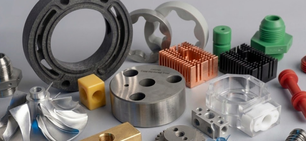
CNC milling produces complex geometries to high precision across a wide range of solid materials, but most work falls into metals and engineering plastics. The choice comes down to two things: how easily the material cuts, which drives tool wear and cost, and its mechanical properties, which decide whether the part holds up in service.
Common Metals
- Aluminium (6061, 7075)
- Brass
- Copper
- Stainless steel (303, 316)
- Carbon steel
- Alloy steels (4140, 4340)
- Cast iron
- Titanium (Ti-6Al-4V)
Common Plastics
- ABS
- Delrin (POM/Acetal)
- Nylon
- PEEK
- Polycarbonate
- PET
Common Uses
CNC milling produces precision parts across every stage of product development, from proving a concept to full batch production. It fits a job when the part needs tight tolerances, the geometry is too complex for simpler methods, and the material is a solid metal or plastic that cuts well.
Key Application Conditions
- Rapid prototyping
- Precision parts
- Complex local features
Aerospace
Titanium structural brackets, turbine impellers, engine housings, and thin-walled aluminium airframe parts, where strength-to-weight and tight tolerances are non-negotiable.
Automotive
Engine blocks, cylinder heads, gearbox casings, and suspension links, in both one-off performance parts and production runs.
Medical devices
Orthopaedic titanium implants, surgical instruments, and diagnostic equipment enclosures, where biocompatibility and geometric accuracy are required.
Electronics
Heat sinks with thin cooling fins, EMI shielding enclosures, and milled aluminium chassis, valued for tight fits and smooth finishes.
Industrial machinery
Machine bases, machine tool components, precision gearboxes, and hydraulic blocks that keep production equipment running.
How to Design Your CNC Milling Project
Most of the cost and delay in a milled part is decided in the CAD model, not on the machine. A CNC machine tool has a finite reach, a spindle can only push so hard, and thin material flexes under a cutter. A handful of design habits keep a part cheap, fast, and accurate.
- Tolerances: standard milling tolerance suits most features. Tight tolerances add cost, so reserve them for critical fits like bearing seats and mating pins.
- Part geometry: design parts so the cutter can reach the desired shape from as few directions as possible. Undercuts and features hidden from every angle cannot be milled.
- Cavity depth: deep, narrow pockets force long, thin cnc milling tools that flex and chatter. Keep pockets shallow relative to the tool where possible.
- Internal corners: a round cutter cannot leave a sharp internal corner. Design in a radius rather than a square edge.
- Wall thickness: thin walls vibrate and distort under the cutter. Thicker walls machine faster, cheaper, and more accurately.
- Holes and threads: use standard drill and tap sizes, and avoid threading to the very bottom of a blind hole.
CNC Milling Vs CNC Turning
Milling and turning are the two main branches of CNC machining. The difference comes down to one thing: what spins.
What Moves
In milling, the workpiece stays clamped and a multi-point cutting tool rotates against it. In turning, the opposite happens. The workpiece spins on a lathe while a single-point tool stays fixed.
What Each Does Well
Turning spins the part around a central axis, so it produces round shapes: shafts, pins, bushings, and threaded rods. It cuts these faster and with better concentricity and finish than milling can.
Milling moves a rotating cutter across a fixed block, so it produces flat faces, pockets, slots, and complex non-round geometry that turning cannot reach.
Which to Choose
Most complex parts use both. A shaft might be turned to its round profile, then moved to a mill for a flat, keyway, or cross-hole. Many mill-turn centres now do both in one setup. The rule is simple: if the part is basically round, start with turning; if it is not, mill it.
CNC Milling Vs 3D Printing
Milling and 3D printing sit at opposite ends of manufacturing. Milling is subtractive, cutting a part out of a solid block. 3D printing is additive, building a part up layer by layer. Neither is better in general. They suit different jobs.
How They Differ
Milling starts with more material than the part needs and removes the rest, which wastes stock but leaves the material at full strength. 3D printing adds only the material the part uses, so it wastes little and can build shapes milling cannot, such as internal channels and hollow lattices. The trade-off is that printed parts are built in layers, which can leave them weaker along the layer lines and rougher on the surface.
Where Each Wins
Milling wins on strength, tolerance, and finish. A milled metal part comes out dense, accurate to fractions of a millimetre, and ready to use with minimal finishing. It is the choice for functional parts that carry load or need tight fits.
3D printing wins on geometry and speed for one-offs. Complex organic shapes, internal features, and quick concept models come out faster and cheaper than milling them, especially in plastic. As volume rises or the part must perform under stress, milling usually takes over.
Which to Choose
Choose by what the part has to do. If it needs strength, tight tolerances, or a smooth finish in metal, mill it. If it needs complex internal geometry, or it is an early prototype where speed matters more than final properties, print it. Many products use both across their life: printed models early on, milled parts once the design is fixed.
Frequently Asked Questions
Q: What does CNC stand for in CNC milling?
A: CNC stands for Computer Numerical Control. It means the milling machine follows a program of numerical instructions, the G-code, rather than an operator working the controls by hand. Numerical control is what separates a CNC mill from a manual machine and is why the process repeats the same result across every part.
Q: Is CNC milling a subtractive manufacturing process?
A: Yes. CNC milling is a subtractive manufacturing process: it starts with a solid block and removes material to reach the final shape. This sets it apart from additive processes like 3D printing, which build a part up instead. The subtractive approach leaves the material at full strength, which is why milling suits load-bearing parts.
Q: What is the difference between CNC milling and CNC machining?
A: CNC machining is the broad term for all computer-controlled cutting processes, including milling, turning, drilling, and routing. CNC milling is one process within that family, defined by a rotating cutter working a fixed workpiece. So every milling job is CNC machining, but not all CNC machining is milling.
Q: What are the steps in the CNC machining process?
A: The CNC machining process runs in five stages: create the CAD model, program the toolpaths in CAM, set up the machine, run the milling cycle, then inspect and finish the part. The design and programming stages carry the most weight, since a well-prepared file is what lets the milling process run to high precision without surprises.
Q: What is a machining centre?
A: A machining centre is a CNC mill built for production, with an automatic tool changer and often a rotating table so it can run many operations in one setup. A horizontal machining centre clears chips well on heavy cuts, while vertical types are more common for general work.
Q: How tight are the tolerances CNC milling can hold?
A: Standard CNC milling holds tolerances around ±0.13 mm, which covers most parts. Tighter tolerances are achievable on critical features but cost more in time and inspection. Specify tight tolerances only where the fit truly needs them.
