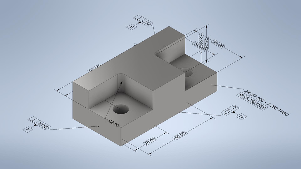
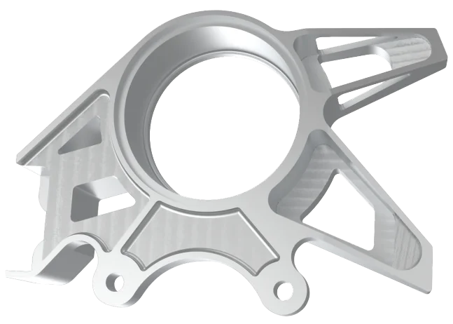
Geometric Dimensioning and Tolerancing (GD&T) is a standardized symbolic language used on engineering drawings to define the allowable variation of a part’s geometry. Standardized under ASME Y14.5 and ISO 1101, GD&T moves beyond basic linear dimensions by using explicit geometric symbols to control a feature’s exact size, shape, orientation, and location.
Rather than specifying rigid, standalone numbers, GD&T establishes functional relationships between part features—ensuring components fit and function correctly during final assembly.
Why it matters for manufacturing:
Removes ambiguity between design and shop floor
Reduces scrap and rework caused by unclear tolerances
Keeps parts interchangeable across batches and suppliers
Lowers cost by tightening tolerances only where function requires it
GD&T vs Traditional Coordinate Tolerancing
Traditional coordinate tolerancing, often called plus/minus (±) tolerancing, sets a separate limit for each linear dimension. A hole’s location might be given as ±0.13mm in X and ±0.13mm in Y. This was the standard method before GD&T, and it still shows up on simple drawings today.
It has four core limitations:
Wrong zone shape. ± tolerancing in X and Y creates a square tolerance zone. But holes and pins are round. What actually matters is the radial distance from the true center, not separate X and Y limits.
No functional relationship.Plain dimensions do not say which surfaces the tolerance is measured from, or in what priority. Two people can read the same drawing and disagree on how to set up the inspection.
No bonus tolerance.± tolerancing gives one fixed limit no matter how the actual feature size comes out. GD&T’s MMC and LMC modifiers let the tolerance grow as the feature departs from its worst-case size, which plain dimensioning cannot do.
Ambiguous stacking. Chains of ± dimensions accumulate tolerance in ways that are hard to predict, especially across multiple features and multiple parts in an assembly.
Aspect
Coordinate (±) Tolerancing
GD&T
Tolerance zone shape
Square or rectangular
Matches the feature: cylindrical for holes, planar for faces
Datum reference
Not defined, left to interpretation
Explicit, ordered (primary, secondary, tertiary)
Bonus tolerance
Not available
Available through MMC and LMC modifiers
Design intent
Describes geometry only
Describes geometry and function
Inspection method
Often manual, open to interpretation
Defined by the standard, repeatable across inspectors
Typical cost impact
Tighter effective tolerance for the same stated value
More usable tolerance for the same stated value, lower scrap
GD&T Symbol Categories
#Category 1 - Form Tolerances
Straightness
There are two variations.
Line (surface) straightness controls a 2D line on a flat or curved surface, checked with a dial indicator across the surface.
Axis straightness controls the center axis of a shaft or hole; add a diameter symbol (⌀) before the tolerance and the zone becomes a cylinder, not just two parallel lines. Common on shafts, rods, and long extrusions that must not bow.
Flatness
The tolerance zone is formed by two parallel planes, and the entire surface must lie between these two planes. No reference is needed because the flatness detection never compares the surface with any external object. It is inspected using a height gauge or a level and an indicator.
Circularity / Roundness
The tolerance zone is two concentric circles on a plane perpendicular to the part’s axis. Every point on that cross-section must fall between the two circles. Checked with a roundness tester, or a V-block and dial indicator for a quick shop-floor check.
Cylindricity
The tolerance zone is two coaxial cylinders spanning the entire length of the feature. Cylindricity rolls circularity, straightness, and taper into one control, which is why it is the strictest and most expensive form control to inspect. Usually checked on a CMM.
#Category 2 - Profile Tolerance
Profile tolerances wrap a 3D tolerance zone around a line or surface of any shape, including freeform curves that other symbols cannot describe. Datum use is optional here, and that choice changes what the tolerance controls. Without a datum, profile only controls form. With a datum, it also controls orientation and location, which is why some engineers use profile of a surface as an all-in-one replacement for several other symbols.
Profile of a line
Establishes a 2D tolerance zone by tracing the ideal curve at each cross-section, then offsetting it by the tolerance value on both sides. Every point on that cross-section’s actual curve must fall inside the zone.
Profile of a surface
Same idea as line profile, but the tolerance zone wraps the entire 3D surface at once rather than one cross-section at a time. This is the go-to control for sculpted or freeform parts.
#Category 3 - Orientation Tolerancee
Orientation tolerances control the angle of a feature relative to a datum. All three always need a datum, because an angle only means something relative to a reference.
Perpendicularity
Controls a 90° relationship to a datum. Surface perpendicularity sandwiches the target surface between two parallel planes set at 90° to the datum. Axis perpendicularity does the same with a cylinder around the target axis, and needs a diameter symbol in the tolerance compartment.
Angularity
Controls any specified angle other than 0° or 90° between the feature and the datum. The basic angle dimension sits elsewhere on the drawing; angularity does not control that angle directly, it controls the tolerance zone that keeps the feature within the stated range.
Parallelism
Controls a 0° relationship to a datum. Works the same way as angularity and perpendicularity, just with the angle fixed at zero. Can apply to a surface or an axis.
#Category 4 - Location Tolerance
Location tolerances define where a feature sits relative to a datum. All three need a datum, and position is by far the most used symbol in all of GD&T.
Position
Position specifies the total allowable variation of a feature’s location relative to established datums. It is almost always paired with a diameter symbol (⌀) to establish a cylindrical tolerance zone, since that shape matches how a round fastener physically engages a hole. It is frequently used with the MMC (maximum material condition) modifier to unlock extra bonus tolerance as the feature size changes.
Concentricity
Controls whether the median points of a feature share a common axis with a datum axis. Removed from the main body of ASME Y14.5-2018, but still seen on older drawings and in some industries. Hard to inspect, since it needs a CMM to find median points rather than surface points. Position usually replaces it.
Symmetry
Controls whether the median points of a feature are symmetric about a datum plane. Also removed from the main 2018 standard body, rarely used, and just as hard to inspect as concentricity.
#Category 5 - Runout Tolerance
Runout tolerances control how much a feature deviates when rotated a full turn around a datum axis. Both symbols always need a datum axis.
Circular Runout
Checked one cross-section at a time as the part completes a full rotation on that axis. Catches circularity and coaxiality errors at each individual cross-section, but not a straightness error running along the axis. Typical setup: part mounted in a V-block or between centers, dial indicator against the surface, one full rotation per cross-section checked.
Total Runout
Checked across the entire surface in one continuous sweep while the indicator also moves along the axis. Catches everything circular runout catches, plus taper and axial straightness. Stricter and more time-consuming to inspect, but the right call when the full surface needs to run true, not just individual slices of it.
How GD&T Works in Engineering Drawings?
Every GD&T callout lives inside a feature control frame (FCF). Reading one left to right gives you four pieces of information:
Geometric characteristic symbol: the first box. Tells you which of the 14 controls applies.
Tolerance value: the allowed variation, sometimes preceded by a zone-shape symbol like ⌀ for a cylindrical zone.
Material condition modifier: MMC (maximum material condition), LMC (least material condition), or RFS (regardless of feature size). Modifiers can unlock bonus tolerance as the feature departs from its stated size
Datum references: one to three letters, in order of priority, showing which datums the tolerance is measured from. A datum itself is a theoretically exact point, line, or plane, not something that physically exists on the part. It comes from a real feature, called a datum feature (a flat face, a locating hole, an edge), which gets labeled with a letter in a square box on the drawing. That letter is what shows up here, inside the FCF.
A leader line connects the FCF to the controlled feature. If there is no leader, the FCF sits next to a basic or diametric dimension, and the tolerance applies directly to that feature of size.
Applications of GD&T
GD&T shows up wherever parts must fit, rotate, or align with tight accuracy. A few industries where it is standard practice:
Aerospace: engine mounts, turbine components, and structural joints carry high stress and near-zero margin for error. Position and profile tolerances keep mating parts interchangeable across suppliers and production runs.
Automotive: engine blocks, transmission shafts, and gear housings rely on runout and orientation tolerances to keep rotating assemblies from vibrating or wearing prematurely.
Medical devices: implants and surgical instruments need location and profile controls tight enough that assembly precision translates directly into patient safety.
Precision machinery and automation: bearing seats, gearboxes, and robotic joints depend on cylindricity and runout to keep rotating parts running true over long duty cycles.
Consumer electronics housings: CNC machined and injection molded enclosures use flatness and position tolerances to keep snap-fits, screw bosses, and mating halves aligned at scale.
Gavin Leo is a content editor at Aria Manufacturing with hands-on experience in CNC machining, Injection molding, materials selection, and part design. Outside of work, he enjoys hiking and collecting mechanical watches.
Custom Quality Parts By Aria
Send your specs. We’ll get back with a quote in 12 hours.
Gavin Leo is a content editor at Aria Manufacturing with hands-on experience in CNC machining, Injection molding, materials selection, and part design. Outside of work, he enjoys hiking and collecting mechanical watches.


 EU
EU