

 EU
EUIn precision manufacturing, creating a hole is often only the first step. While standard drilling opens up passage in a workpiece, it rarely provides the extreme tight tolerances or smooth surface finishes required for high-precision components like hydraulic valves, bearing seats, or dowel pin alignments.
This is where CNC Reaming comes into play. As a critical secondary machining process, reaming bridges the gap between rough hole-making and ultra-precise hole finishing.
What is Reaming in CNC Machining?

CNC reaming is a precision hole-finishing process that uses a multi-fluted cutting tool (a reamer) to remove a tiny layer of material from a pre-drilled or bored hole. The purpose is to enhance the accuracy and surface finish of the hole by performing a slight enlargement of the hole diameter.
Reaming typically removes only 0.15 mm to 0.35 mm on diameter (about 0.1 mm per side) to achieve micron-level accuracy, superior roundness, and surface finishes down to Ra 0.8 µm.
Differences Between Reaming, Drilling, and Boring
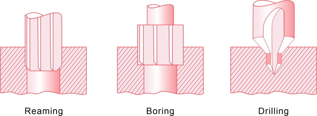
All three are hole-making or hole-finishing operations, but they serve different purposes at different stages.
Drilling creates the initial hole by plunging a rotating drill bit into solid material. It removes the bulk of the stock and is fast, but the resulting hole has limited accuracy. Typical drilling tolerance sits around ±0.1 mm, and surface finish is rough.
Boring enlarges an existing hole using a single-point cutting tool. It corrects positional errors and improves straightness. Boring is the right choice when the hole centre must be shifted or when the diameter exceeds standard drill sizes.
Reaming is a finishing step. It does not create holes or correct position. It takes a pre-drilled (or pre-bored) hole and brings it to final size with a tight tolerance and smooth wall. Reamers follow the existing hole path, so the hole must already be reasonably straight and centred before reaming begins.
Quick Preview
How Does Reaming Work?
Reaming is a finishing step, not a roughing operation. The quality of the final hole depends on proper preparation, the right tool, and correct cutting parameters.
Preparing the Pre-Drilled Hole:
A reamer follows the existing hole and cannot fix positional errors or straightness issues. The pre-drilled hole should be 0.15 mm to 0.35 mm smaller than the final target diameter, leaving just enough stock for the reamer to cut cleanly. Too little stock causes rubbing and poor finish; too much overloads the tool.
Tool Selection:
Selection depends on material, hole size, tolerance, and production volume. HSS reamers suit general-purpose work at lower costs. Solid carbide reamers handle harder materials, higher speeds, and longer production runs. Straight-flute types work well for through holes, while spiral-flute types are ideal for blind holes because the helix pulls chips upward.
Parameter Setup:
Reaming uses lower speed and higher feed than drilling—a typical starting point is 50% to 70% of drilling speed with two to three times the feed rate. If the feed is too slow, the reamer burnishes instead of cutting; if too fast, the hole becomes oversized or tapered.
The Cutting Process:
The reamer enters the hole with a continuous feed motion. Its multiple flutes cut a thin, even layer from the hole wall simultaneously. This balanced radial load is what produces superior roundness compared to single-point boring.
Retraction and Coolant:
Coolant runs throughout the process to lubricate, cool, and flush chips. For through holes, the reamer feeds straight through and retracts quickly. For blind holes, it must reverse out at the same feed rate to avoid scoring the finished surface, as trapped chips will scratch the fine finish.
Types of Reaming Tools and Selection Guide
Choosing the right reamer is half the job. The wrong type leads to poor finish, short tool life or scrapped parts. This section covers the most common types and when to use each one.
Hand Reamers
Hand reamers have a long taper lead and a square shank end for use with a tap wrench. They are turned by hand at low speed. These are used for fitting work, maintenance and one-off jobs where a machine setup is not practical. They are not suitable for production work.
Machine Reamers
Machine reamers have a shorter chamfer lead and are designed for use in drill presses, lathes and CNC machining centres. They cut faster and produce more consistent results than hand reamers. Most CNC reaming work uses this type.
Straight Flute Reamers
The most common type. The flutes run parallel to the tool axis. They work well for through holes in steel, aluminium and brass. Simple to manufacture, easy to resharpen and widely available in standard sizes.
Spiral Flute Reamers
The flutes wrap around the body in a helix. This design pulls chips out of the hole during cutting, making it the better choice for blind holes or materials that produce long, stringy chips. Spiral flute reamers also produce a smoother cut with less chatter.
Adjustable Reamers
The cutting diameter can be expanded within a small range by adjusting the blades. Useful when a non-standard hole size is needed or when wear compensation is required. They trade some accuracy for flexibility compared to solid reamers.
Carbide-Tipped Reamers
A steel body with brazed carbide cutting edges. They combine the vibration damping of a steel shank with the wear resistance of carbide. A good choice for medium to high volume production in harder steels and cast iron.
Solid Carbide Reamers
The entire tool is made from carbide. They offer the best rigidity, wear resistance and dimensional stability. Ideal for high-speed reaming, abrasive materials and long production runs where consistency over thousands of holes matters. Higher cost but longer tool life offsets it in volume work.
When is Reaming Required?
Not every hole requires reaming. CNC reaming should be specified in the design phase under the following conditions:
-
- Tight dimensional tolerances:When a drawing specifies ISO fit classes such as H6, H7 or H8 that drilling cannot reliably hit.
- High-quality surface finish requirements:When internal surfaces need a smooth finish (Ra < 1.6 µm) to prevent fluid leakage or mechanical friction.
- Alignment and dowel pin placement:Press-fit or sliding-fit holes for dowel pins that hold precision mould bases and machinery together.
- Bearing and bushing seats:Internal bores where rotating shafts or bearings require uniform contact pressure.
Advantages and Disadvantages of Reaming
Advantages
-
- High dimensional accuracy:Reaming achieves tolerances of H7 or tighter, which drilling and boring alone cannot match consistently.
- Superior surface finish:Surface roughness down to Ra 0.4 µm is achievable, reducing or eliminating the need for secondary finishing operations like honing or grinding.
- Excellent repeatability:Multi-fluted reamers produce consistent hole size and roundness across large production runs with minimal variation part to part.
- Fast cycle time:Compared to boring or grinding a hole to the same tolerance, reaming removes material quickly with a single pass.
- Low cost per hole:Reamers are relatively inexpensive tools. Combined with fast cycle times, the cost per finished hole is low compared to alternative finishing methods.
Disadvantages
-
- Cannot create holes:Reaming is a finishing operation only. A pre-drilled or pre-bored hole is always required first.
- Cannot correct position:A reamer follows the existing hole path. If the drilled hole is off-centre, the reamed hole will be too.
- Limited stock removal:Reamers are designed to remove 0.1 to 0.35 mm on diameter. Anything beyond this range risks tool damage and poor results.
- Sensitive to setup:Poor workholding, excessive runout or incorrect parameters lead to chatter, taper or oversized holes quickly.
- Tool wear in abrasive materials:Materials like cast iron, fibreglass and titanium alloys wear reamers faster and may require frequent replacement or more expensive carbide tooling.
Industrial Applications
Automotive Industry
Engine blocks, cylinder heads, transmission housings and brake components all contain holes that require reaming. Valve guide bores, piston pin holes and connecting rod bores must hold tight fits to function under high speed and high temperature. Reaming ensures these critical bores meet H7 tolerances consistently across mass production volumes.
Aerospace
Aerospace parts demand extreme precision and zero tolerance for failure. Reaming is used on turbine shaft bores, landing gear pin holes, hydraulic manifold ports and structural fastener holes. Materials like titanium and Inconel are common in aerospace, and reaming provides the controlled, low-force finishing these difficult alloys require.
Medical Devices
Surgical instruments, orthopaedic implants and diagnostic equipment contain precision bores that must meet strict dimensional and surface finish standards. Reamed holes in bone screws, implant housings and fluid delivery components ensure proper fit, smooth fluid flow and biocompatibility. Surface finish is especially critical here because rough internal surfaces can harbour bacteria or cause tissue irritation.
Precision Machinery
Mould bases, die sets, linear guide housings and spindle assemblies rely on reamed holes for accurate alignment. Dowel pin holes in mould plates must be reamed to matching tolerances so the mould halves align perfectly on every close. Spindle bores and bearing seats need consistent roundness and finish to minimise vibration and extend service life.
Common Issues in Reaming and How to Avoid Them
Oversized holes
The most frequent problem. Common causes include excessive stock allowance, worn reamer, too high cutting speed or tool runout in the holder. Check the pre-drilled hole size, verify reamer wear and reduce speed. Ensure the toolholder has less than 0.005 mm runout.
Poor surface finish
Usually caused by feed rate too low (burnishing instead of cutting), insufficient coolant or built-up edge on the reamer. Increase feed rate slightly, ensure adequate coolant flow and switch to a coated reamer if built-up edge persists.
Chatter marks
Visible vibration patterns on the hole wall. Often caused by lack of rigidity in the setup, excessive spindle speed or an unsupported workpiece. Reduce speed, improve workholding and use a reamer with unequal flute spacing if available.
Tapered holes
The hole diameter varies from entry to exit. This happens when the reamer deflects due to excessive stock removal, misalignment between spindle and hole, or a worn chamfer lead. Reduce stock allowance, check spindle alignment and replace worn tools.
Bell-mouthed holes
The entry of the hole is larger than the rest. Caused by excessive runout, a damaged chamfer lead or the reamer chattering at entry. Ensure the pre-drilled hole has a clean chamfer, minimise toolholder runout and reduce entry feed if needed.
Chips scratching the finished surface
Happens during retraction when chips get trapped between the reamer margins and hole wall. Maintain coolant flow during retraction, use spiral-flute reamers for better chip evacuation and never retract at rapid traverse in blind holes.
Reaming Case Study
A European client in the automation industry ordered a batch of 304 stainless steel linear guide blocks. Each block had four bore holes designed to accept Ø8.2 mm dowel pins with an H7 tolerance (8.200 to 8.215 mm) and a surface finish requirement of Ra 0.8 µm.
Initial drilling produced holes at Ø8.0 mm with a surface finish of approximately Ra 6.3 µm. The drilled holes were round enough in shape but could not meet the tolerance or finish requirements for a press-fit dowel connection.
We used solid carbide straight-flute reamers at a cutting speed of 60 m/min and a feed rate of 0.12 mm/rev with through-tool coolant. Each hole took approximately 8 seconds to ream. The finished holes measured Ø8.205 to Ø8.210 mm with a surface finish of Ra 0.6 µm, well within the H7 specification.