

 EU
EU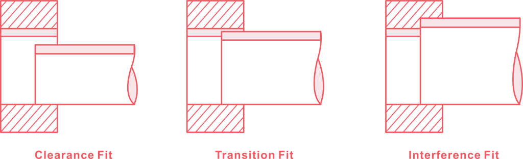
The different types of fits in engineering are clearance fit, interference fit, and transition fit. They define the amount of clearance or interference between two mating parts so assemblies can be loose, tight, or intermediate. This affects assembly function, dimensional accuracy, tolerance control, production cost, and overall product performance.
For engineers, product designers, OEMs, and procurement managers working on mechanical assemblies, understanding these engineering fits helps you specify how parts should mate before production.
This article covers fit definitions, the main fit types and their subtypes with applications and examples, the hole and shaft basis system, and the criteria for choosing the right fit for your project.
What Is An Engineering Fit?
In engineering, a fit describes the relationship between two or more components in an assembly. A standalone part does not have a fit. The fit is determined by the amount of clearance or interference between mating parts, and their dimensions control it.
For example, a shaft and bearing use an interference fit. The dimensions are tight enough that the shaft and bearing inner race lock together and rotate as one unit. A clearance fit in the same application would fail because the bearing could not grip the shaft or transmit torque.
Most assemblies have predetermined engineering fits to ensure proper function and avoid tolerance conflicts between mating components.
Importance of Tolerances in Fits
Before I explain all the engineering fits, it is better to understand tolerance and tolerance ranges. Tolerance is the maximum or minimum allowable variation from a reference measurement. Dimensional tolerance exists due to machining capabilities as no machine can cut a piece to the exact dimension shown on the technical drawing.
Nominal Dimension
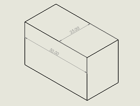
Nominal dimension is the basic dimension you expect your part to have, or the nominal diameter used as the reference size before ISO and ANSI tolerance frameworks are applied. The nominal dimension is not accurate and manufacturers will try to stay close to this specified dimension. Nominal dimension has no tolerance variation mentioned.
Tolerance
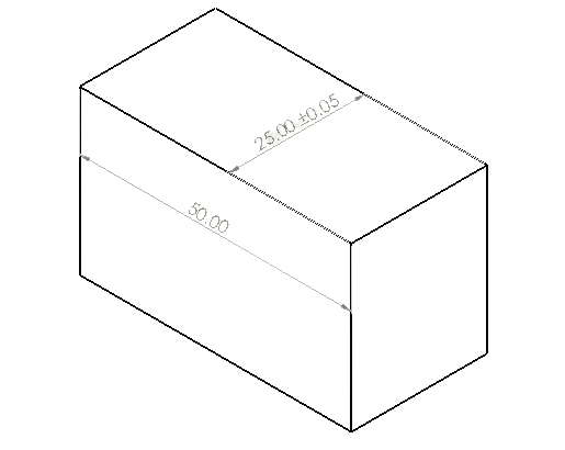
Deviations added to the basic dimension define the tolerance coding in mechanical fits. ISO 286 uses tolerance zones to set the allowable variation from the nominal size.
For example, a bilateral deviation of ±0.05 mm on a 25 mm dimension means the part can range from 24.95 mm to 25.05 mm. Standards such as ISO 286 (H7, g6, etc.) and ANSI B4.1 provide standardised codes for specifying these tolerance limits on holes and shafts.
3 Main Types of Fits
Each fit type is defined by the dimensional relationship between the hole and shaft tolerance zones. The following sections cover each category, its standardised subtypes, ISO class examples, and typical applications.
- Clearance Fit
- Interference Fit
- Transition Fit
Clearance fit
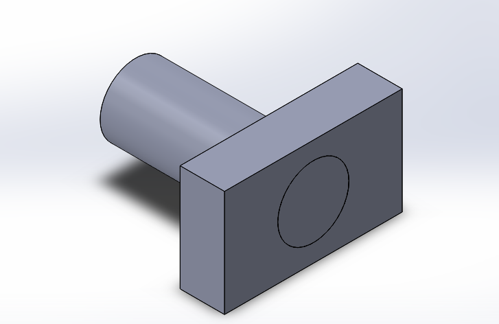
A clearance fit always leaves a positive gap between the mating parts. The minimum hole size is larger than the maximum shaft size. This allows relative movement, sliding, or rotation between the components.
Maximum clearance occurs when the hole is at its largest allowable size and the shaft is at its smallest. Minimum clearance occurs when the hole is at its smallest and the shaft is at its largest.
Types of Clearance Fits
Sliding Fit
Sliding fit is a clearance fit with minimal clearance between mating parts. The parts can slide freely but remain snug, making this fit ideal for accurate positioning and close alignment.
- Application: Sliding doors, sliding gears, shafts and bushings, sliding rods
- Example: H7/g6
Loose Running Fit
Loose running fit has the largest clearance of all clearance fits. Accuracy between mating parts is not critical. The wide gap allows the assembly to function even when dust or debris enters the fitting.
- Application: Construction machinery, agricultural equipment, dust-prone linkages
- Example: H11/e11
Free Running Fit
Free running fit, also known as easy slide fit, provides generous clearance for free movement between parts. It can tolerate minor misalignment and is suited to applications with thermal expansion.
- Application: High-temperature shafts, long multi-bearing drives, hinged rods
- Example: H8/f7
Close Running Fit
Close running fit provides small clearance with good dimensional accuracy. It is used where parts need controlled movement and precise location at speed.
- Application: High-speed machine tool spindles, precision drill sleeves, machine slides
- Example: H8/g7
| Fit Subtype | ISO Class | Description | Typical Applications |
| Sliding Fit | H7/g6 | Snug clearance for precise location with free movement | Sliding gears, alignment dowels, valve stems, precision bushings |
| Loose Running Fit | H11/e11 | High clearance, tolerates dirt, debris, and thermal expansion | Construction machinery, agricultural equipment, dust-prone linkages |
| Free Running Fit | H8/f7 | Generous clearance for easy sliding and thermal compensation | High-temperature shafts, long multi-bearing drives, hinged rods |
| Close Running Fit | H8/g7 | Small clearance for controlled, accurate movement | High-speed spindles, precision drill sleeves, machine slides |
Interference fit
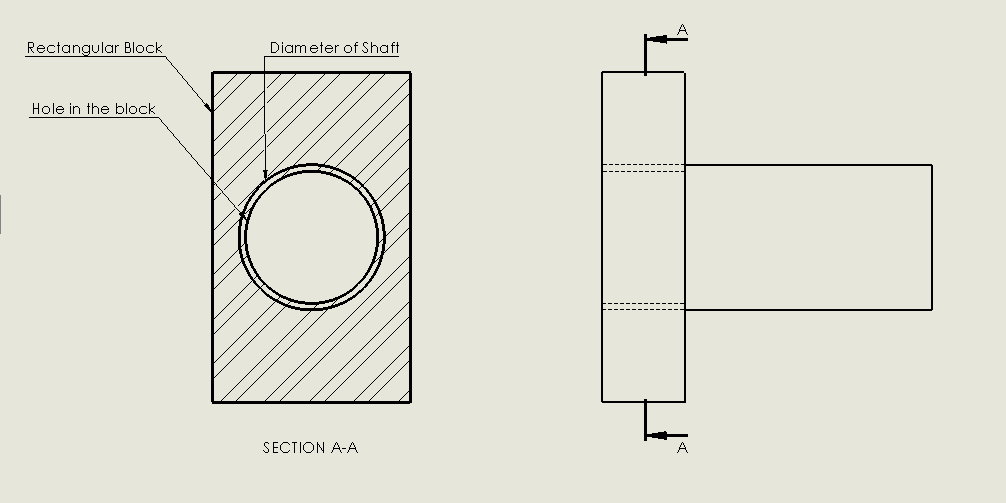
In an interference fit, the shaft is intentionally larger than the hole. Assembly requires mechanical force or thermal methods, creating a rigid friction joint that prevents relative motion.
Maximum interference occurs when the shaft is at its largest and the hole is at its smallest. Minimum interference occurs when the shaft is at its smallest and the hole is at its largest.
Types of Interference Fits
Driving Fit
Driving fit requires moderate force, typically applied with a cold press. The interference is small enough that parts can still be disassembled without damage.
- Application: Heavy-duty pulleys, brake discs, removable gears on shafts
- Example: H7/n6
Press Fit
Press fit joins two mating parts by pressing the shaft into the hole using a heavy mechanical press. The interference is moderate, making press fit common in bearing and bushing installations.
- Application: Camshafts, precision bearing inner rings, steel bushings
- Example: H7/p6
Force Fit
Force fit requires significant mechanical force from a hydraulic press or similar equipment. The parts are intended for permanent assembly. Unlike shrink fit, force fit relies on pressing alone without thermal methods.
- Application: Locomotive wheel axles, heavy machinery drive gears
- Example: H7/s6
Shrink Fit
Shrink fit uses thermal methods to join parts. The shaft is cooled to contract its diameter, or the hole is heated to expand, or both. Once temperatures equalise, the interference locks the parts permanently. Tolerances are tight, often fractions of a millimetre, to prevent cracking or excessive deformation.
- Application: High-torque turbine blades, heavy ring gears, permanent shaft couplings
- Example: H7/u6
| Fit Subtype | ISO Class | Assembly Method | Typical Applications |
| Driving Fit | H7/n6 | Moderate force via cold press or soft mallet | Heavy-duty pulleys, brake discs, removable gears on shafts |
| Press Fit | H7/p6 | Heavy mechanical press | Camshafts, precision bearing inner rings, steel bushings |
| Force Fit | H7/s6 | High-pressure hydraulic press, permanent joint | Locomotive wheel axles, heavy machinery drive gears |
| Shrink Fit | H7/u6 | Heating the hole or freezing the shaft | High-torque turbine blades, heavy ring gears, permanent shaft couplings |
Transition Fit
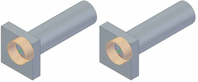
A transition fit sits between clearance fit and interference fit. Depending on where the actual dimensions fall within the tolerance band, the assembly can produce either slight clearance or slight interference. Transition fits are used where precise alignment and minimal play are critical.
Types of Transition Fits
Push Fit
Push fit allows assembly with light hand force or a soft mallet. The fit can produce a small clearance or a small interference depending on where the actual dimensions fall within the tolerance zone.
- Application: Precision dowel pins, valve guides, change gears, removable locating pins
- Example: H7/j6
Wringing Fit:
Wringing fit is a tight transition fit where parts are assembled by twisting or wringing them together. It produces near-zero clearance, sitting right at the boundary between clearance and interference. Assembly requires firm hand pressure with a slight rotational motion.
- Application: Gauge blocks, gear fittings, rudders
Example: H7/h6
Similar Fit
Similar fit gets its name from both parts having nearly identical dimensions. Only light force is needed to join them. The result can be a small clearance or a small interference.
- Application: Precision bearing seatings, removable sleeves, gearbox spigots
- Example: H7/k6
Fixed Fit
Fixed fit has tighter interference than similar fit and requires a press to assemble. It provides accurate location with stronger holding force.
- Application: Permanent locational pins, rigid couplings, motor shaft rotors
- Example: H7/m6
| Fit Subtype | ISO Class | Assembly Behaviour | Typical Applications |
| Push Fit | H7/j6 | Light hand force or rubber mallet | Precision dowel pins, valve guides, change gears, removable locating pins |
| Similar Fit | H7/k6 | Light mechanical tapping | Precision bearing seatings, removable sleeves, gearbox spigots |
| Fixed Fit | H7/m6 | Moderate arbor press force, slight interference predominates | Permanent locational pins, rigid couplings, motor shaft rotors |
Basis of Fits: Hole and Shaft System
Engineering fits are specified using either a hole basis system or a shaft basis system. These systems define which part has the fixed reference dimension, which part carries the tolerance variation, and how the tolerance range is standardised across engineering drawings.
Hole Basis System
In a hole basis system, the hole has a fixed reference dimension and the shaft size varies to achieve the desired fit. The lower deviation of the hole is always zero, meaning the hole is machined to its nominal size as the baseline. The shaft tolerance is then adjusted above or below to create clearance, interference, or transition.
Hole basis is the most common system in manufacturing because it is easier and cheaper to adjust shaft dimensions through turning or grinding than to resize a hole after drilling or reaming.
Hole Basis System Example
Using the ISO tolerance table with a nominal diameter of 40.00 mm and a tolerance code of H9/e9 (a clearance fit):
The capital letter H refers to the hole. The lowercase letter e refers to the shaft.
- H9 gives a lower deviation of 0.000 mm and an upper deviation of +0.062 mm.
- e9 gives an upper deviation of -0.050 mm and a lower deviation of -0.112 mm.
So the hole can range from 40.000 mm to 40.062 mm. The shaft can range from 39.888 mm to 39.950 mm. The gap between them confirms a clearance fit.
Shaft Basis System
In a shaft basis system, the shaft has the fixed reference dimension and the hole size varies to achieve the fit. The upper deviation of the shaft is always zero. The hole tolerance is adjusted to create the required clearance or interference.
Shaft basis is less common than hole basis but is used when the shaft is a standard size that cannot be modified, such as cold-drawn bar stock or a purchased motor shaft. Both ISO 286 and ANSI B4.1 provide tolerance tables for shaft basis fits.
Shaft Basis System Example
Using the ISO tolerance table with a nominal diameter of 40.00 mm and a tolerance code of D9/h9 (a clearance fit):
The lowercase letter h refers to the shaft (fixed reference). The uppercase letter D refers to the hole (variable).
- h9 gives an upper deviation of 0.000 mm and a lower deviation of -0.062 mm.
- D9 gives a lower deviation of +0.080 mm and an upper deviation of +0.142 mm.
So the shaft can range from 39.938 mm to 40.000 mm. The hole diameter can range from 40.080 mm to 40.142 mm. The gap between them confirms a clearance fit.
How to Choose Between Clearance, Interference, and Transition Fit
Selecting the right engineering fit depends on several factors. The most common considerations are listed below.
Assembly Function
If the parts need to slide or rotate freely, use a clearance fit. If the joint must be permanent with no relative movement, use an interference fit. If you need precise alignment with minimal play but occasional disassembly, a transition fit is the best choice.
Precision and Cost
Tighter fits require tighter tolerances, which increase machining time and production cost. An interference fit may also need thermal assembly methods such as shrink fitting or hot pressing, adding further expense. Specify only as tight a fit as the application actually requires.
Material and Environment
Thermal expansion, corrosion, and material hardness all affect how a fit performs in service. Softer materials deform more under interference. High-temperature environments can close a clearance gap or loosen an interference joint over time.
Production Volume
For high-volume production, hole basis fits with standard tooling reduce cost. Custom fits with narrow tolerance bands may be justified for low-volume, high-precision assemblies but are expensive to scale.
Conclusion
Engineering fits define how mating parts interact in a mechanical assembly. Clearance fits allow movement, interference fits lock parts permanently, and transition fits provide precise location with minimal play.
The tighter the fit, the higher the production cost and the lower the freedom of movement. Selecting the right balance between precision and cost is critical for every project.
Both the hole basis system and shaft basis system provide standardised tolerance references under ISO 286 and ANSI B4.1. Consistent use of these systems across engineering drawings ensures that parts mate correctly in production.
