

 EU
EU
True position in GD&T is the geometric control that defines the exact location of a feature on a part. It uses datums as reference points and a tolerance zone to show how far the actual feature can deviate from its nominal position. Engineers, designers, and shop floor managers use true position to control feature location during manufacturing and inspection.
This article covers what true position means, how to read the feature control frame, the types of tolerance zones, how to calculate true position with a worked example, how bonus tolerance works, and how to inspect true position on machined parts.
What is True Position?

In ASME Y14.5, there is no separate “True Position” symbol. The standard uses the term “Position.” True position is the shop floor term for the theoretically exact location of a feature defined by basic dimensions from the datums.
The position symbol on a drawing marks where a feature like a hole, slot, or pin should be located relative to datum surfaces. Basic dimensions fix the nominal coordinates. True position refers to that ideal, exact point. For holes and pins, the controlled element is the feature’s central axis.
True position is always used with datums. Without datums, there is no reference to measure from, and the callout has no meaning.
How to Read the Feature Control Frame
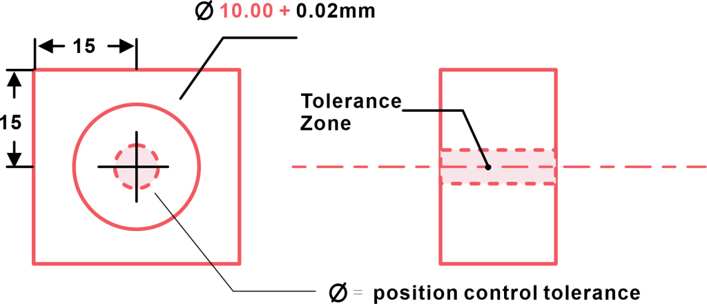
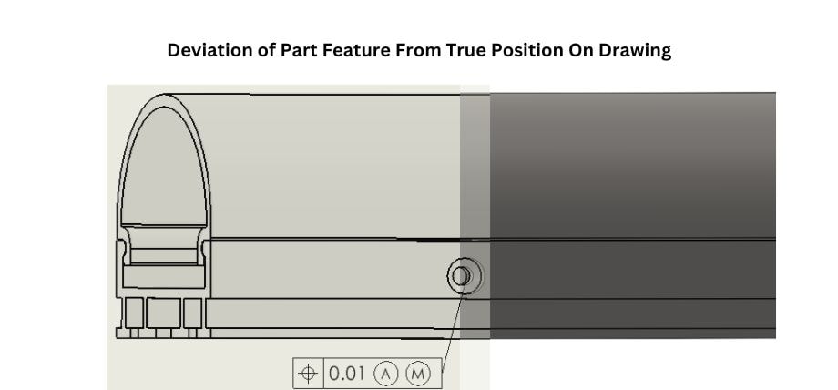
The feature control frame (FCF) is a rectangular box on the drawing that carries the full true position callout. It communicates the type of geometric control, the tolerance value, and the reference datums for a feature.
A typical true position FCF is read from left to right across its compartments:
- First compartment contains the position symbol (⌖). This identifies the geometric characteristic as position control.
- Second compartment contains the diameter symbol (⌀) followed by a tolerance value, such as 0.05. The diameter symbol means the tolerance zone is cylindrical. The number defines the diameter of that zone.
- Material condition modifier, such as (M), appears after the tolerance value. MMC means the stated tolerance applies when the feature is at its maximum material size. For a hole, maximum material is the smallest allowable diameter.
- Datum references such as A, B, and C define the datum reference frame. These are listed in order of priority: primary, secondary, and tertiary.
Each compartment carries specific meaning. Missing or misreading any part leads to incorrect inspection or manufacturing setup.
True Position Tolerance Zone
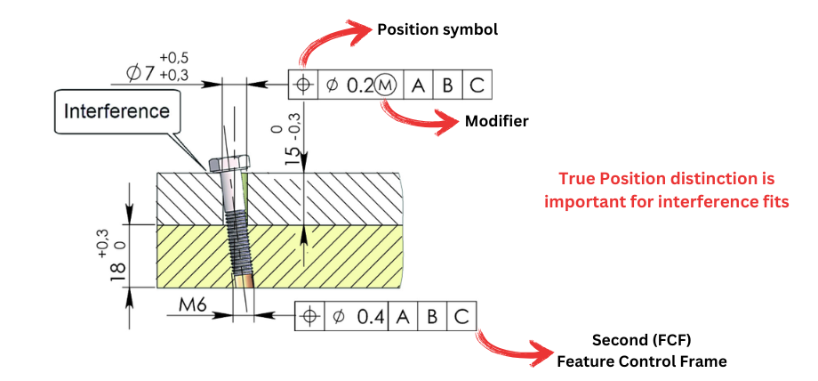
The tolerance zone defines the allowable deviation from the nominal position. For true position, the most common zone shape is cylindrical.
Imagine the basic dimensions place a hole’s ideal centre axis at a specific X, Y coordinate relative to the datums. The cylindrical tolerance zone is centred on that ideal axis. The actual hole axis must fall within this cylinder.
For example, if a feature control frame specifies ⌀0.2 mm, the actual hole axis must lie within a cylinder of 0.2 mm diameter centred on the basic position. The maximum allowable deviation from the ideal axis is 0.1 mm in any radial direction.
This cylindrical zone is three-dimensional. It extends through the full depth of the feature, controlling the axis along its entire length.
True Position vs Linear Tolerance
There are different ways to control feature location. The two most common are linear tolerancing and true position tolerancing. They use different tolerance zone shapes and produce different results.
Linear Tolerancing
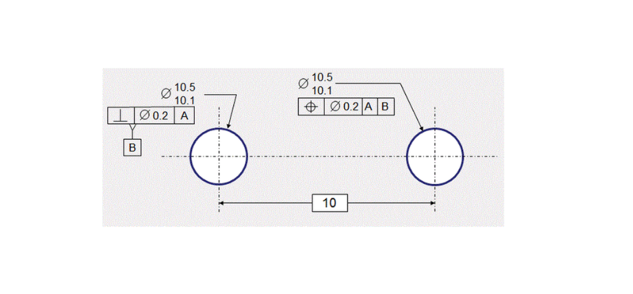
Linear tolerances use ± values to define allowable deviation in X and Y separately. For example, a hole at 20.00 mm ± 0.2 mm means the centre can range from 19.8 mm to 20.2 mm in that direction.
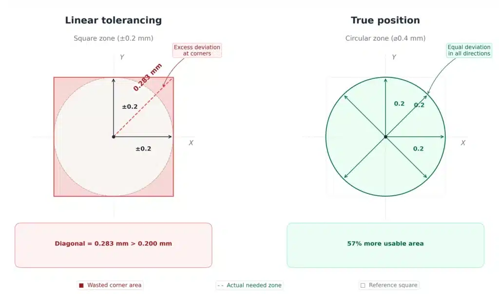
This creates a square tolerance zone. The hole centre can move ±0.2 mm in X and ±0.2 mm in Y independently. The problem is at the corners. If the centre shifts +0.2 mm in both X and Y at the same time, the actual deviation from nominal is 0.283 mm (the diagonal of the square), not 0.2 mm. This means a square zone allows more variation in the diagonal directions than intended.
For round features like holes and pins, this is a poor fit. The mating part does not care which direction the hole drifts. It only cares about the total distance from nominal.
The diagram below illustrates this difference:
True Position Tolerancing
True position uses a circular (or cylindrical in 3D) tolerance zone. The tolerance is equal in all directions. A ⌀0.2 mm true position zone means the hole centre can deviate up to 0.1 mm in any direction from nominal.
Compared to a square zone of the same width (±0.1 mm), the circular zone gives about 57% more usable area. This is because the circular zone fills in the diagonal corners that the square zone wastes. In practice, true position provides more tolerance to the manufacturer without loosening the functional requirement.
True position also simplifies inspection. One measurement (distance from nominal) replaces separate X and Y checks.
Types of Tolerance Zones in GD&T
Different GD&T controls use different tolerance zone shapes. The table below summarises the main types and their typical applications.
| Tolerance Zone | Shape | Typical Use |
| Cylindrical (⌀) | 3D cylinder around an axis | True position of holes, pins, bosses |
| Circular (○) | 2D ring in a cross-section | Roundness control for shafts, bearings |
| Planar (⏤) | Two parallel planes | Flatness of surfaces |
| Square (±) | Rectangular box in X/Y | Linear tolerancing of feature locations |
For true position, always use a cylindrical tolerance zone specified with the diameter symbol. Square tolerance zones belong to linear dimensioning, not GD&T position control.
How to Calculate True Position
True position deviation is calculated from the difference between the measured feature location and the basic (nominal) location.
Formula:
- TP = 2 × √[(X_actual – X_basic)² + (Y_actual – Y_basic)²]
The result is the diameter of the smallest cylindrical zone that contains the measured axis. The factor of 2 converts the radial deviation to a diametral value, since the tolerance zone is defined as a diameter.
Worked Example
A hole has basic dimensions of X = 25.000 mm and Y = 30.000 mm from the datum reference frame. After machining, the measured centre is at X = 25.050 mm and Y = 30.080 mm.
Step 1: Find the deviations.
- ΔX = 25.050 – 25.000 = 0.050 mm
- ΔY = 30.080 – 30.000 = 0.080 mm
Step 2: Calculate the radial distance.
- √(0.050² + 0.080²) = √(0.0025 + 0.0064) = √0.0089 = 0.0943 mm
Step 3: Multiply by 2 to get the diametral true position.
- TP = 2 × 0.0943 = 0.189 mm
If the feature control frame specifies ⌀0.20 mm, this hole passes (0.189 < 0.200). If the tolerance were ⌀0.15 mm, it would fail.
Material Condition Modifiers
Modifiers appear in the feature control frame after the tolerance value. They change how the tolerance applies based on the actual produced size of the feature.
- MMC (M) stands for Maximum Material Condition. For a hole, MMC is the smallest allowable diameter. For a pin, MMC is the largest allowable diameter. When MMC is specified, the stated tolerance applies only at the MMC size. As the feature departs from MMC (hole gets larger, pin gets smaller), bonus tolerance is added.
- LMC (L) stands for Least Material Condition. This is the opposite: for a hole, LMC is the largest allowable diameter. Bonus tolerance is added as the feature departs from LMC toward MMC.
- RFS (S) stands for Regardless of Feature Size. The tolerance applies at any produced size. No bonus tolerance is available. In ASME Y14.5-2009, RFS is the default when no modifier is stated.
Bonus Tolerance with Maximum Material Condition
Bonus tolerance is extra positional tolerance gained when the actual feature size is not at its maximum material condition size. The bonus equals the difference between the actual feature size and the MMC size.
Example:
A hole has a size tolerance of ⌀10.0 to ⌀10.4 mm. The true position callout is ⌀0.2 mm at maximum material condition.
| Actual Feature Size | Bonus Tolerance | Total Position Tolerance |
| ⌀10.0 mm (MMC) | 0.0 mm | 0.2 mm |
| ⌀10.1 mm | 0.1 mm | 0.3 mm |
| ⌀10.2 mm | 0.2 mm | 0.4 mm |
| ⌀10.3 mm | 0.3 mm | 0.5 mm |
| ⌀10.4 mm (LMC) | 0.4 mm | 0.6 mm |
Bonus tolerance is widely used in hole pattern designs where functional gauging is the acceptance method. It reflects the reality that a larger hole can tolerate more feature position shift and still assemble with its mating pin. This material condition approach is standard for automotive and aerospace position control.
How To Select Datum
A datum is a reference point, plane, or datum surface used for measuring and setup. When selecting a datum, use a hierarchy by assigning primary datum, secondary, and tertiary datum labels based on how each surface constrains degrees of freedom.
- Primary datum (Datum A): The main reference surface. Choose the surface that makes the most contact or provides the most stable setup. This is usually the largest flat face or the bottom surface of the part. The primary datum constrains the most degrees of movement.
- Secondary datum (Datum B): Constrains additional degrees of freedom. On a turned part, the shaft’s central axis often serves as Datum B when it is the referenced secondary axis.
- Tertiary datum (Datum C): Locks the remaining degree of freedom. This is often a smaller feature like a slot, hole, or edge.
A consistent datum structure helps keep hole position stable across setups. If a hole pattern is referenced to Datum A, Datum B, and C, all holes in that pattern should use the same datum order. Changing datum order between features in the same pattern creates conflicting requirements.
When the primary datum is a cylindrical feature such as a bore or shaft, the datum axis of that feature becomes the reference. The true position of other features is then measured from this datum axis.
Composite True Position Tolerance
A composite feature control frame has two or more rows sharing the same true position symbol. The upper row controls the pattern location relative to the datum reference frame (PLTZF, Pattern Locating Tolerance Zone Framework). The lower row controls the feature-to-feature relationship within the pattern (FRTZF, Feature Relating Tolerance Zone Framework).
The upper row uses all three datums (Datum A, Datum B, and C) and a larger position tolerance. It controls where the entire hole pattern sits on the part. The lower row may reference fewer datums or only one datum, with a tighter position tolerance. It controls how evenly spaced and oriented the features are relative to each other.
Composite true position is common for bolt hole patterns. The assembly may tolerate a slight shift in the overall pattern location, but the individual hole positions within the pattern must be closely spaced to match the mating bolt circle. This allows a single true position callout to control both pattern-level and feature-level position tolerance.
How to Measure True Position
To measure true position of a feature, the actual position must be compared to the ideal position defined by the basic dimensions. Several inspection methods are available.
Coordinate Measuring Machine (CMM)
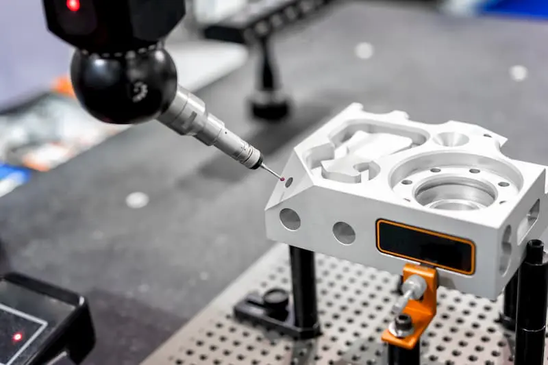
A coordinate measuring machine (CMM) is the most common tool for true position measurement. The CMM probe touches multiple points on the measured feature and datum surfaces. The software calculates the actual location relative to the datum reference frame and compares it to the basic dimensions.
CMMs provide high accuracy and can measure true position of complex parts with many features in a single setup. They are the standard for first article inspection and detailed quality control reports. The CMM automatically applies the true position formula and reports the position deviation for each measured feature.
Functional Gauging
A functional gauge (go/no-go gauge) checks whether a controlled feature at its worst-case actual feature size and actual position will still assemble. The gauge pin diameter equals the virtual condition of the hole. Virtual condition is calculated as the MMC size minus the true position tolerance. For example, a ⌀10.0 mm MMC hole with a ⌀0.2 mm true position tolerance has a virtual condition of ⌀9.8 mm. If a gauge pin of ⌀9.8 mm fits through the hole, it passes.
Functional gauging is faster than CMM inspection and is commonly used for production-line quality control. It works best when the true position callout uses the maximum material condition modifier, because the virtual condition is a fixed value.
Open Setup with Dial Indicators
For simpler parts, a dial indicator mounted on a surface plate can measure feature position. The part is set up on the datum surfaces and the indicator is zeroed at the basic dimensions. The measured position of the feature is read directly as deviation from the ideal position.
This method is less accurate than a CMM but is accessible for shops without expensive metrology equipment. For small parts where contact measurement is difficult, an optical system such as a profile projector can also be used. The projector displays a magnified image of the feature on a screen, and the measured center is compared to the ideal position using reticle overlays or digital readouts.
GD&T True Position Applications
GD&T true position is used across many manufacturing sectors. Some of the most common applications include the following.
Hole patterns are the most frequent application of true position. Bolt hole patterns, dowel pin holes, and mounting hole patterns all require tight position control to ensure interchangeability. True position of each hole in the pattern is measured relative to the datum reference frame.
Automotive and aerospace CNC components rely heavily on GD&T true position. Engine blocks, cylinder heads, gearbox housings, aircraft structural brackets, and landing gear components all use true position callouts to control hole position, pin location, and feature position. Interchangeability ensures mass-produced components fit together on the assembly line without rework.
Circular features such as bearing bores, O-ring grooves, and shaft journals use true position to control the feature’s location relative to the datum axis. The actual position of the central axis of these circular features must fall within the cylindrical tolerance zone.
Different features like counterbores, countersinks, slots, and bosses also use true position when their exact location is critical for function or assembly.
Common Mistakes with True Position
Confusing true position with linear tolerance is the most frequent error. Linear ± values create square tolerance zones. True position creates cylindrical tolerance zones. They are not interchangeable.
Another common mistake is forgetting to use basic dimensions. True position requires basic (untoleranced, boxed) dimensions for the exact dimension of the nominal location. If standard toleranced dimensions are used instead, the position tolerance stacks with the size tolerance and the design intent is lost.
Omitting datums is also an error. True position without datums cannot be measured or inspected. Every true position callout must include at least one datum reference. Using only one datum in a feature control frame for true position means the position control only constrains orientation, not location.
Applying the wrong material condition modifier leads to rejected parts or missed failures. Always confirm whether the true position callout specifies maximum material condition, least material condition, or RFS (default) before inspection.
Ignoring bonus tolerance under maximum material condition is another common mistake. If the true position callout specifies MMC and the actual feature size is larger than maximum material condition, the total allowable position tolerance increases. Failing to account for this extra tolerance may lead to rejecting good parts.
FAQs
What is true position in GD&T?
True position is the theoretically exact location of a feature defined by basic dimensions from datum references. The true position symbol and the true position tolerance zone control how far the actual feature can deviate from that ideal position.
How do you calculate true position?
Use the true position formula: TP = 2 × √[(X_actual – X_basic)² + (Y_actual – Y_basic)²]. Take the square root of the sum of the squared deviations and multiply by 2. This gives the diametral position deviation. Compare the calculated true position to the position tolerance value in the feature control frame. A true position calculator can automate this.
Can you have true position without datums?
In most cases, true position requires datum references. Without datums, there is no fixed frame to measure feature location from. However, ASME Y14.5 does allow position without explicit datums in specific cases. These include the lower tier of a composite position callout, coaxial features, and self-referencing symmetrical patterns.
What is Rule #1 in GD&T?
Rule #1 (Envelope Principle) states that the form of a regular feature of size must not extend beyond a boundary of perfect form at MMC. It links size and form control.
What is Rule #2 in GD&T?
Rule #2 states that RFS (Regardless of Feature Size) is the default for all geometric tolerances unless a modifier (MMC or LMC) is explicitly stated.
What is the difference between true position and actual position?
True position is the theoretically perfect, ideal position of a feature as defined by basic dimensions. The actual position is the measured position of the produced feature on the physical part. The position deviation between the actual position and the true position is calculated using the true position formula.
