

 EU
EUCNC turning is a subcategory of the CNC machining process and one of the most widely used forms of CNC technology. The motor shafts, threaded connectors, and knurled knobs you come across are, for the most part, turned parts.
CNC turning spins the raw material at speed and feeds a stationary tool into it, shaping round or cylindrical parts to tight tolerances. Its real value is repeatability, holding an exact diameter across thousands of identical units.
This guide covers how turning works, the operations a lathe performs, the materials suited to it, and where the process fits in real production.
What is CNC Turning?
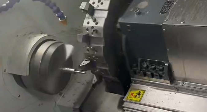
CNC turning is a subtractive manufacturing process that shapes round parts. The workpiece is clamped in a spindle and spun at high speed, while a stationary cutting tool feeds into the surface to remove material until the part reaches its final diameter and profile.
The defining characteristic of turning is its kinematic configuration: the workpiece rotates while the tool remains fixed. This stands in contrast to CNC milling, where the tool rotates against a stationary workpiece. Because the material rotates continuously around a central axis, turning naturally produces symmetrical geometries, including stepped shafts, tapers, external threads, and precision internal bores.
How CNC Turning Works
Turning a finished part is a sequence, not a single action. It runs from a digital model through machine setup to the cutting itself, then any finishing the part needs. Each phase ensures the part meets its dimensional and surface requirements before it moves on.
Create 3D Model File
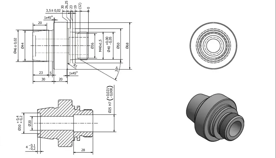
Work starts with a CAD model of the part. The model carries the full definition: dimensions, chamfers, threads and tolerances. Designing for turning means favouring axisymmetric profiles, keeping wall thicknesses consistent and calling out standard radii where possible. Anything left ambiguous here surfaces later as a problem on the machine, so the drawing is where accuracy begins.
Converting the model to G-code
CAM software, or computer aided manufacturing, processes the geometry and generates the tool paths, along with the spindle speeds, feed rates and depth of cut for each pass. It exports this as G-code, the instruction set the lathe controller reads. A manufacturing engineer usually reviews the output, since a clean CAD model can still produce an inefficient or unsafe tool path.
Stationary Tool & Materials
On turning machine tools, raw stock is chosen to match the part, most often round bar in steel, aluminium or engineering plastic. A non-round profile such as hex bar is sometimes used when it saves later work. The stock is mounted in the spindle or fed from an automatic bar feeder. Cutting inserts, usually tungsten carbide or coated high-speed steel, are selected for roughing and finishing, then loaded into the turret.
CNC Machines Setup
The operator loads the stock, sets the workpiece offset, and calibrates tool lengths, often using a probing system. Correct alignment prevents dimensional errors and protects tools from collisions once the spindle brings the stock up to speed. Coolant lines are aimed at the cutting point to control heat and clear chips. A dry run or first-article check confirms the setup before full production begins.
Run the Turning Process
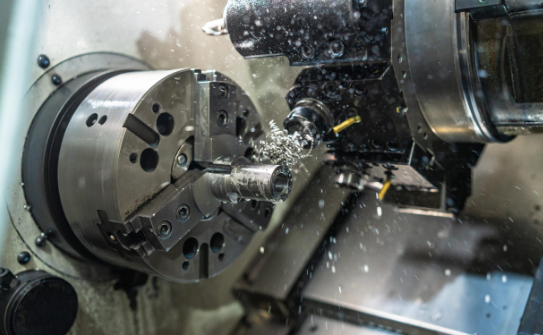
The spindle rotates the workpiece up to speed and the tool follows the programmed path. Cutting almost always splits into two stages: roughing and finishing.
- Roughing runs first, using a lower speed and a heavier depth of cut to strip away bulk material fast until the part reaches its rough shape. Accuracy is not the goal here, throughput is, so the pass deliberately leaves a small amount of stock on the part for the finishing cut to clean up.
- Finishing then removes that remaining stock. It uses a higher speed and a light depth of cut, which reduces cutting force and lets the tool hold the final diameter and produce a smooth surface. Conservative finishing parameters also improve tool life. Pushing speed and feed too hard at this stage causes deflection or chatter, both of which show up as poor finish or a part out of tolerance.
Post-processing
Few parts ship straight off the lathe. The component is first parted off from the bar stock, then deburred to remove sharp edges left by cutting. Depending on the application, it may be bead blasted, polished, anodised, plated or heat treated. These steps add corrosion resistance, wear resistance or a specific finish that turning alone does not provide. If a part also needs secondary features, further machining processes may follow.
Types of CNC Turning Operations
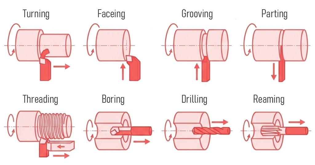
A lathe executes a range of common CNC turning operations, each defined by the cutting tool profile and feed direction. Most complex components require com
bining several operations within a single automated program. These processes split into external operations (shaping the outer diameter) and internal operations (machining the face or inner bore).
Turning
Turning is the core operation the process is named after, using a single-point cutting tool along the length of a rotating workpiece to reduce the outer diameter. Straight turning moves the tool to create a consistent diameter. Feeding the tool at an angle produces taper turning, which creates a cone-like shape, and guiding it along a curved path produces a contour. Most profiles are reached across several passes at increasing depth, with the tool path running parallel to or at an angle to the workpiece’s rotational axis.
Facing
Facing cuts across the end of the workpiece rather than along its length. The tool feeds in perpendicular to the axis, removing a thin layer to form a smooth, flat end face. It is often the first operation on a new bar, setting a clean reference length and surface for everything that follows, such as drilling or grooving.
Grooving
Grooving cuts a narrow channel into the surface, with the tool fed radially into the side of the part. A single pass produces a groove the width of the tool, and wider grooves need multiple passes. Common uses are seats for O-rings, snap rings and oil seals. A groove reduces the cross-section at that point, so its depth and position are worth checking on parts that carry load.
Boring
Boring enlarges and refines an existing hole from the inside. A single-point boring bar enters the pre-drilled cavity and cuts along the internal surfaces, improving the hole’s finish as well as concentricity, location accuracy, and diameter tolerance beyond what a drill alone can hold. Internal tapers, steps and contours are cut the same way. It is the standard route to an accurate bore in bearing housings, valve bodies and engine cylinders.
Threading
Threading cuts a helical thread onto the part. A pointed tool tracks along the surface in time with the spindle rotation, so each pass follows the same helix. Internal and external threads are cut inside a bore and on the outer diameter respectively. This synchronisation of feed to rotation is what sets the thread pitch, and full depth usually takes several passes. It produces the fasteners, fittings and adjustment screws that need to mate with a matching part.
Parting
Parting, also called cut-off, separates the finished part from the bar stock. A narrow blade feeds radially into the side until it reaches the centre and the part detaches. The motion resembles grooving, but the tool travels all the way to the axis. Because the blade is thin and deep, it is one of the more fragile setups, so feed and rigidity matter. This is normally the last operation in a cycle.
Drilling
Drilling produces a hole along the rotational axis as the drill is fed into a flat surface perpendicular to that axis. The drill is held in the tailstock or turret while the workpiece rotates against it, so the hole runs true to the axis of rotation. It is often the first step before boring, reaming or tapping, and on its own it makes lubrication holes, dowel holes and pilot holes. On modern turning equipment, drilling is one of the operations often combined in a single setup.
Knurling
Knurling is a forming operation, not a cutting one: a knurling tool with hardened patterned wheels presses into the rotating surface, indenting a straight or diamond pattern rather than removing material. The result is a textured grip on knobs, handles and thumb screws. The pattern also helps on press-fit parts and as a plain visual marking.
Reaming
Reaming finishes a pre-drilled hole to a precise diameter and a smooth wall. A multi-fluted reamer enters a hole drilled slightly undersize and removes a small amount of material. It is a sizing operation, used when a drilled hole alone is not accurate enough, for example a bore that must take a dowel pin to a close fit.
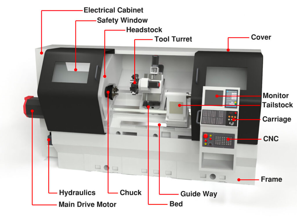
Components Of CNC Turning Machine
Knowing the machine helps in reading a quote, judging what a part will cost, and understanding why a supplier suggests one approach. Modern CNC lathes are built from a set of core components, each with a defined job. The description below follows a standard horizontal lathe setup.
Headstock
The headstock sits at one end and drives everything that rotates, housing the main motor, the spindle and its bearings. The workholding mounts to the spindle here. Two figures decide its reach: swing, the largest diameter that clears the bed, and spindle bore, the thickest bar you can feed through.
Chuck and Collet
The chuck grips the workpiece and transmits the spindle rotation. A three-jaw self-centring chuck holds round or hexagonal stock and centres it automatically, while a four-jaw chuck suits off-centre or irregular parts. A collet grips a part around its full circumference, giving a more concentric hold for small-diameter bar work.
Tailstock
The tailstock supports the free end of a long workpiece, which would otherwise flex away from the tool and chatter. Its quill advances against the part, often hydraulically, to hold it steady, and it also carries drills and reamers. It cannot be used when the end face itself is being machined.
Lathe Bed
The bed is the base the whole machine is built on, a heavy iron casting chosen for mass and stiffness. It holds the headstock, tailstock and carriage in fixed alignment and absorbs cutting vibration. Its top is ground into guideways that let the carriage slide true, so any flex in it shows up directly in the part.
Carriage
The carriage carries the tool and moves it against the workpiece, riding the bed on guideways driven by ball screws and servo motors. It moves along the Z-axis, one of the machine axes, parallel to the spindle axis to set the length of a cut, while its cross-slide moves along the X-axis, the other of the basic machine axes, to set the diameter. These two movements are the basis of every turning operation.
Turret
The tool turret holds multiple cutting tools at once, commonly eight to twelve, each mounted in its own tool holders within the turret, and indexes to bring any one into position on command. This lets a lathe move from roughing to grooving to threading without a manual tool change. A turret with live tooling adds powered tools, so milling and cross-drilling happen in the same setup.
Control Panel
The control panel is the interface between operator and machine. It runs the G-code and lets the operator set offsets, adjust overrides and monitor spindle load. Behind it, a controller from a family such as Fanuc, Siemens or Haas coordinates speed, feed and tool position in real time. This closed-loop control is part of modern CNC systems, rather than the more manual open-loop behaviour of older NC machines.
Beyond these core parts, a production lathe relies on supporting systems. A coolant system manages heat and flushes chips, a chip conveyor clears swarf over a long run, and a bar feeder loads fresh stock so the machine can turn part after part unattended. These rarely appear on a drawing, but they are much of why turning is economical at volume.
CNC Turning Materials
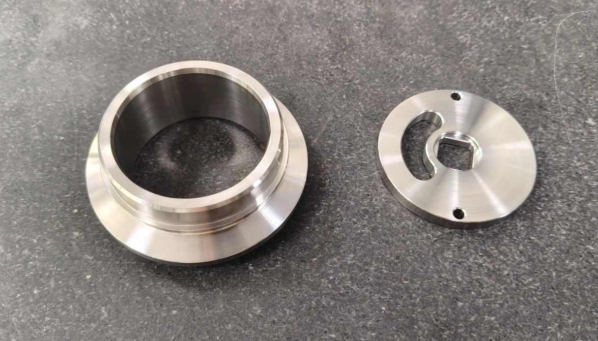
Turning works with any material rigid enough to be held in a chuck and to resist the cutting tool without deforming. In practice this means metals and rigid plastics.
Metals
Metals are the most turned materials by far. Common choices include aluminium, brass, mild and alloy steels, stainless steel and titanium.
Plastics
Rigid plastics suit parts that need light weight, chemical resistance or electrical insulation. Common choices include acetal (Delrin), nylon, PTFE and PEEK.
Advantages of CNC Turning
Turning earns its place for round parts through a mix of precision, speed and consistency that few processes match.
High precision and consistency
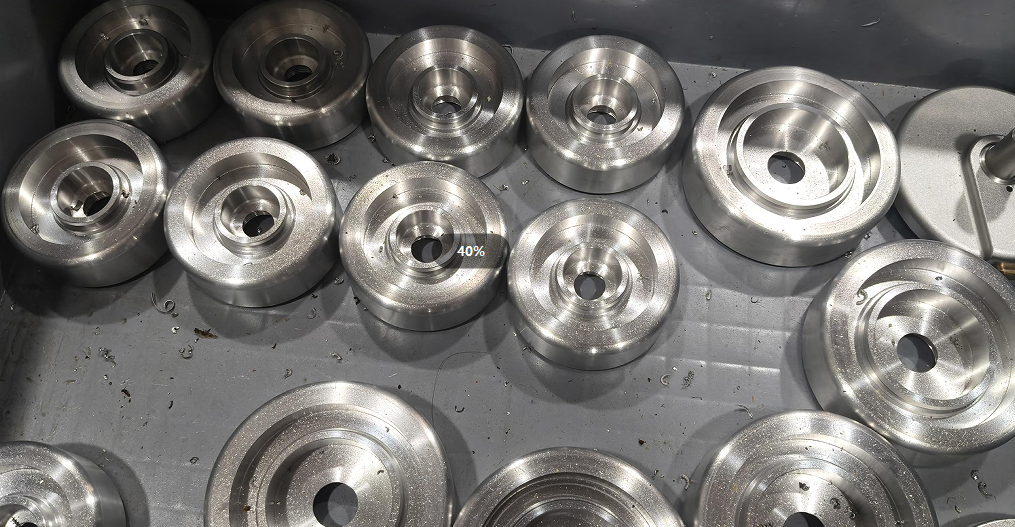
Computer control removes operator variation. Once a program is proven, precision machining allows the lathe to repeat the same operations across thousands of cycles while holding tight tolerances on diameter and length, maintaining dimensional accuracy. High-end CNC turning achieves tolerances as tight as ±0.0001 inches. The first part and the last part match, which is what production depends on.
Superior surface finish
The workpiece spins continuously against a fixed tool edge, and that steady contact produces a smooth surface straight off the machine. Turning, boring and facing often reach a finish that needs no secondary polishing or grinding, saving a step and its cost.
Fast and cost-effective for round parts
A round feature on a mill needs multi-axis motion and long tool paths. On a lathe the tool only travels along a spinning part, so a full diameter is cut in one pass. Faster cycles mean lower machine hours and less tool wear, which shows up directly in unit cost.
Scalable across volume and size
The same machine handles a single prototype or a full batch, and moving to a new design is a programming change rather than new tooling. Machines exist to suit almost any scale too, from parts the size of a watch pin to shafts weighing hundreds of kilograms.
Live tooling reduces setup
A turning center with live tooling can perform off-centre drilling, tapping, keyway milling, and other secondary operations in one setup, and some shops classify this kind of combined machine as a machining center. Keeping these operations on the lathe avoids re-fixturing, removes a source of alignment error and shortens lead time.
Safe, enclosed operation
Modern lathes run fully enclosed, containing chips and coolant behind guarding and interlocks. Because the cutting is automated, the operator monitors the job rather than standing in the cutting zone, which lowers the risk that comes with manual machining. In practice, that makes enclosed CNC operation safer and more consistent than manual lathes.
Common Uses
Turning appears wherever a design calls for a precise round part, which is almost everywhere. CNC turning is widely used across various industries, including automotive and aerospace, where tight tolerances and structural reliability are essential.
Automotive
Drive systems run high in volume and tight in tolerance, handling real rotational speed and load. Turning produces crankshafts, camshafts, transmission shafts, wheel hubs and brake pistons, along with the high-concentricity motor shafts and bearing housings now used in electric vehicles.
Aerospace and defence
The same precision is required, but in harder materials. Turbine shafts, landing gear pins, hydraulic actuator sleeves and high-strength fasteners are turned from titanium and alloys like Inconel, where a part out of tolerance is not an option.
Medical device manufacturing
Much of this work uses Swiss-style turning for small, intricate parts. Bone screws, dental abutments, spinal rods and surgical instruments are turned from biocompatible metals and plastics. A smooth, burr-free finish matters as much as the dimension, since it affects patient safety.
Oil, gas and energy
These parts seal under pressure in harsh conditions, so concentricity and thread accuracy decide whether they hold. Turning makes valve stems, pump shafts, drill collars, downhole tool bodies and heavy pipe couplings, often from large-diameter steel bar.
Electronics and industrial machinery
The rest runs high in quantity and often small in size. Turning produces brass connector pins, copper heat-sink parts, standoff spacers, and the bearings, bushings and couplings that keep general machinery running, held to tight tolerances across large runs.
Recognising a turning part
A few signals point to turning before a supplier is even involved. The part is symmetrical around one axis, its cross-section is round whether solid or hollow, and it can start from bar stock. When a design fits that description, a lathe is usually the fastest and cheapest route to it. Parts with that profile are often classed as cnc turning parts.
What are the key differences between CNC milling and CNC turning?
Milling and turning are two different machining methods within CNC machining, and the choice comes down to part geometry. The core difference is one reversal: in turning the workpiece spins and the tool stays fixed, while in milling the tool spins and the workpiece stays fixed on CNC milling machines.
This also shows in the axes: a turning centre usually works in two (X and Z), while milling machines may use up to five axes for complex contours. Turning suits round parts like shafts and bores, milling suits flat and prismatic parts like brackets and pockets.
| Feature | CNC Turning | CNC Milling |
| What moves | Workpiece rotates, tool fixed | Tool rotates, workpiece fixed |
| Cutting tool | Single-point tool | Multi-flute cutter |
| Cutting action | Continuous | Interrupted |
| Best geometry | Round: shafts, bores, threads | Flat and prismatic: pockets, slots, faces |
| Typical parts | Shafts, pins, valve bodies | Brackets, housings, plates |
Other machining methods may be a better fit when a part is flat or highly prismatic rather than rotationally symmetric.
The two often work together. A round part with a few flats or cross-holes needs both, which is why many shops run mill-turn centres that combine them. For a full breakdown of when to choose each, see our dedicated guide on CNC milling vs CNC turning.
Why Choose Aria CNC Turning Centers?
Choosing a turning supplier is less about the machine and more about what surrounds it: whether the finish, the tolerances and the delivery hold up once the order scales. A few things set the work at Aria apart on those terms.
Turning rarely ends at the lathe. Most parts need finishing, and some need milling, moulding or sheet metal work alongside. Aria runs CNC machining, injection moulding, sheet metal fabrication and surface finishing in-house, so a turned part can move straight to anodising, plating or assembly without leaving the supply chain. That removes the handoffs that add cost and lead time when finishing is subcontracted.
For buyers in Europe, the practical friction is usually distance and communication. Aria has an European office & CNC workshop in Denmark, which gives a local point of contact for quotes, drawings and follow-up while production runs at a China cost base.
Frequently Asked Questions
Q: What are the different types of CNC lathe machines?
A: CNC lathes are grouped by spindle orientation and capability. Horizontal lathes are standard for shaft and bar turning. Vertical CNC turning centers suit heavy, large-diameter components. Swiss-type lathes specialize in high-precision, small-diameter slender parts, while multi-axis turning centres integrate live tooling for combined turning and milling.
Q: What are the downsides of CNC turning?
A: Turning is built for round parts, so flat or off-axis features need a second process like milling. It removes material as waste because it remains a subtractive manufacturing technology rather than a reshaping process. Setup and tooling carry a fixed cost that makes very small runs expensive per part, and most machines cut one part at a time.
Q: What is a CNC lathe?
A: A CNC lathe is a CNC lathe machine that performs turning, and one of the computer controlled lathes used for cylindrical work. It spins the workpiece while a computer-controlled tool feeds in to cut the shape. The controller sets spindle speed, feed and tool position, which is what lets it hold tight tolerances and repeat a part across a run. Many CNC lathes also support various cutting tools for turning, drilling, or threading.
Q: How to calculate CNC turning cost?
A: There is no single price. Cost builds from material, machine time (driven by complexity and number of passes), and setup and programming spread across the run. Tooling, tolerances and finishing add the rest. Because setup is fixed, cost per part drops sharply at volume. Send a drawing for a real figure.
Q: What is CNC in simple terms?
A: CNC stands for computer numerical control. It means a machine follows a digital program, written as G-code from a CAD model, instead of an operator working it by hand. The program directs every movement, so the same part comes out accurately every time.
Q: Is CNC turning the same as a lathe?
A: Not quite.A lathe is the machine. Turning is the process it performs. A CNC lathe is a lathe run by computer control, and a turning center can also combine turning with milling or drilling, which helps produce more complex geometries on cylindrical parts. CNC turning is that machine cutting a part. Turning is the action, the lathe is the tool.
