

 EU
EUEnd milling sits at the centre of most machine shops. It shapes prototypes, production parts and tooling across aerospace, automotive, medical and electronics work. This guide covers how the process works, the tools used, the parameters that control quality, and the problems that show up on the shop floor.
What Is End Milling?
End milling is a versatile machining process that uses a rotating cutting tool, called an end mill, to remove material from a workpiece. Unlike a drill, an end mill can cut in multiple directions. It removes material axially, radially, or in a combined motion, which lets it produce slots, pockets, contours and complex 3D surfaces from a single tool.
The end mill is held in a spindle and moved along programmed paths, usually on a CNC milling machine or machining centre. The workpiece stays fixed in most setups, while the tool travels along the X, Y and Z axes. This flexibility is what separates the end milling process from simpler processes like face milling, drilling and other tools, and it is why the process shows up in nearly every stage of part production, from roughing a block down to size through to finishing a mould cavity.

How Does End Milling Work?
The basic idea is simple. A rotating tool with sharp cutting edges engages the workpiece and shears away material in small chips. The details of how that happens, and how well it happens, depend on several linked factors: how the part is held, how the spindle and tool interact, how the tool moves, and how the chips get cleared away.
Setup and Workpiece Clamping
Before any cutting starts, the workpiece needs to be held securely. A vice, fixture or clamping system keeps the part still while cutting forces try to push it around. Poor clamping is one of the most common causes of dimensional error and vibration, so fixture design gets as much attention as the toolpath itself on tight-tolerance jobs.
The part also needs to be located accurately against the machine’s coordinate system. This usually means touching off the workpiece origin with an edge finder, probe or dial indicator, then confirming the setup with a test cut. A few minutes spent here saves a lot of scrapped material later.
Spindle Rotation and Tool Engagement
Once the part is fixed, the spindle spins the end mill at a set speed, measured in revolutions per minute. As the tool rotates, its cutting edges, called flutes, engage the material and peel off chips. The engagement point matters: too much contact and the tool overheats or deflects, too little and the cut becomes inefficient.
Tool engagement is described by radial depth of cut and axial depth of cut. Radial engagement controls how much of the tool’s diameter is buried in the material sideways. Axial engagement controls how deep the tool cuts downward. Balancing the two keeps cutting forces manageable and extends tool life.
Axis Movement and Toolpath
CNC controls move the tool along a programmed path while the spindle rotates. Simple operations use straight lines and arcs. Complex 3D surfaces use continuous, calculated paths generated by CAM software, often with thousands of small linear or curved segments.
Toolpath strategy affects both cycle time and surface quality. A well-planned path keeps engagement consistent, avoids sudden direction changes that shock the tool, and minimises air cutting where the tool moves without removing material.
Material Removal and Chip Evacuation
As the tool cuts, chips form and need to leave the cutting zone. If they don’t, they get re-cut, which dulls the tool and damages the surface finish. Chip evacuation relies on flute geometry, cutting fluid or air blast, and sensible depth of cut settings.
Deep slots and pocketing operations are particularly prone to chip packing, since the chips have less room to escape. Peck cycles, reduced stepdowns and high-pressure coolant all help clear chips from confined spaces.
Climb Milling vs. Conventional Milling
There are two ways to orient the cut relative to tool rotation. In climb milling, the tool rotates in the same direction as the feed, so the chip starts thick and thins out. In conventional milling, the tool rotates against the feed direction, so the chip starts thin and thickens.
Climb milling generally gives a better surface finish and less tool wear, because it avoids the tool rubbing before it bites. It does need a rigid machine and minimal backlash, since the cutting force tends to pull the workpiece into the tool. Conventional milling is more forgiving on older or less rigid machines, though it produces more heat and a rougher finish. Most modern CNC shops default to climb milling wherever the setup allows it.
Cutting Tool Materials (HSS, Carbide, Coatings)
The material an end mill is made from decides how fast it can cut, how long it lasts, and what it can cut through. High speed steel, or HSS, is tough and cost effective, and it handles interrupted cuts well, but it loses hardness at high temperatures and wears faster than harder alternatives.
Solid end mills made from carbide run at much higher speeds and hold an edge far longer than HSS. They are more brittle, so they suit rigid setups with controlled vibration rather than manual or older machines, which makes them well suited to high speed machining. Coatings add another layer of performance.
Titanium nitride, titanium aluminium nitride and diamond-like coatings each reduce friction, resist heat, or protect against abrasive wear, depending on the coating chemistry and the material being cut. Choosing the right combination of substrate and coating is often the difference between a tool lasting one job or fifty.
Types of End Mill Cutters
End mills come in many geometries and end mill sizes, each suited to a particular job. The features that make end mills different from one another affect surface finish, cycle time and tool life as much as the machine parameters do. Picking the right milling tool matters just as much.
Square End Mills
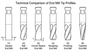
Square end mills, also called flat end mills, have a flat cutting face perpendicular to the tool axis. They are the general-purpose choice for slotting, profiling, pocketing and facing. Most machinists reach for a square end mill first, before considering anything more specialised.
Ball End Mills
Ball end mills, sometimes called ball nose end mills, have a rounded, hemispherical tip. They are built for 3D contour work, mould and die cavities, and any surface with intricate contours or fillets. Because the cutting edge is a radius rather than a sharp corner, they leave a smooth finish on curved geometry, though they need tighter stepover control to hold a consistent surface finish.
Corner Radius / Corner Rounding End Mills
These corner radius end mills combine a flat cutting face with a small radius at the corner, rather than a sharp 90 degree edge or a full ball profile. The radius reduces stress concentration at the corner of the tool, which helps it survive heavy roughing and resist chipping. Parts that need a small fillet at internal corners, without switching to a full ball end mill, are a common use case.
Roughing End Mills
Roughing end mills have a serrated or wavy cutting edge that breaks chips into smaller pieces. This lets them remove material quickly at higher feed rates while spreading cutting forces across multiple contact points. The tradeoff is a rougher surface finish, so roughing tools are almost always followed by a finishing pass with a different tool.
Finishing End Mills
Finishing end mills have a continuous, sharp cutting edge and are run at lighter depths of cut. Their job is surface quality, not material removal rate. They typically follow a roughing operation once the bulk of the material has already been cleared.
Dovetail End Mills
Dovetail end mills cut an angled, undercut profile in a single pass, producing the classic dovetail slot used in sliding joints and locking mechanisms. They are a specialised tool, used specifically when a part needs that interlocking geometry rather than a straight-sided slot.
V-Bit End Mills
V-bit end mills, sometimes called V-groove or engraving tools, come to a sharp conical point. They are used for engraving, chamfering and fine detail work where a flat-bottomed tool would not reach into a sharp corner or edge angle to produce a clean V-shaped groove.
Tapered End Mills
Tapered end mills have a conical body instead of a straight cylindrical one. They are common in mould and die work, where draft angles need to match the taper of the tool, and in deep, narrow cavities where a straight tool would be too weak to reach the bottom without excessive deflection.
Flute Count and Helix Angle Selection
Flute count changes how a tool behaves in cut. Two-flute end mills have more room between flutes for chip clearance, which suits softer materials like aluminium and plastics where large chips need to escape quickly. Four-flute and higher flute counts remove material more slowly per rotation but offer more cutting edges in contact, which suits harder materials like steel and stainless steel where chip volume is lower.
Helix angle affects how the cutting edge shears into the material. A higher helix angle, typically 40 to 45 degrees, gives a shearing action that produces a better finish and lower cutting forces, and it suits softer, gummy materials. A lower helix angle, around 30 degrees, gives a stronger edge that holds up better in harder materials, at the cost of a slightly rougher finish.
Matching End Mills to Materials
Different materials behave differently under a cutting edge. Some are soft and gummy, some are hard and abrasive, some conduct heat well and some trap it right at the cutting zone. Choosing a tool and coating that suits the material type in front of you avoids most of the common failure modes, from built-up edge to premature wear.
| Material Category | Material Properties | Recommended Tool / Coating | Notes |
| Aluminium | Soft, gummy, high thermal conductivity, prone to built-up edge | Uncoated or ZrN-coated carbide, 2 to 3 flutes, high helix angle (40 to 45 degrees) | High spindle speeds work well. Sharp edges and good chip evacuation matter more than hardness. |
| Stainless steel | Work-hardens quickly, low thermal conductivity, gummy chips | Carbide with TiAlN coating, 4 flutes, moderate helix angle | Keep consistent feed to avoid rubbing, which accelerates work hardening. Use coolant to manage heat build-up. |
| Titanium alloys | Low thermal conductivity, high strength retained at temperature, reactive with tool coatings at high heat | Carbide with AlTiN or similar high-temperature coating, low helix angle, rigid tooling | Heat concentrates at the cutting edge rather than dispersing into the chip. Lower speeds and heavier feeds reduce dwell time at the edge. |
| Brass / Copper | Soft, ductile, prone to smearing rather than clean shearing | Uncoated carbide or HSS, sharp positive geometry, 2 flutes | Copper in particular can gum up flutes. Polished flutes and good chip clearance help. |
| ABS | Low melting point, prone to melting and re-adhering if overheated | Uncoated carbide, 2 flutes, high helix angle, sharp edges | Run higher speeds with light depth of cut. Avoid excessive heat build-up, which softens the surface. |
| POM (Acetal / Delrin) | Rigid, low friction, machines cleanly | Uncoated carbide, 1 to 2 flutes | Produces long, stringy chips. Good chip evacuation and sharp tools prevent melting at the cut line. |
| Acrylic / Polycarbonate | Brittle (acrylic) or tough and impact-resistant (polycarbonate), both heat-sensitive | Single-flute or two-flute carbide with high helix angle and polished flutes | Acrylic chips easily if fed too aggressively. Polycarbonate needs careful heat control to avoid melting and re-welding to the tool. |
Types of End Mill Operations
End mills carry out a range of distinct operations, each with its own toolpath logic and parameter set.
Slotting and Profiling
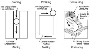
Slotting cuts a channel into the material using the full width of the tool, engaging both sides of the flute at once. It generates the most heat and cutting force of the common operations, since the tool is fully buried on both sides. Profiling, by contrast, follows the outer or inner boundary of a part, cutting on one side of the tool only, which allows for higher feed rates and better tool life since engagement is lighter.
Contouring and 3D Surfacing
Contouring follows a defined 2D or 3D boundary to shape a part’s edge or profile. 3D surfacing extends this to complex contours, typically using ball end mills and closely spaced toolpaths to build up a smooth surface across a mould cavity, turbine blade or organic shape. Surface finish in 3D work depends heavily on stepover distance and tool stepdown, since these determine the height of the small ridges, called scallops, left between passes.
Key Process Parameters for End Milling
Getting good results from end milling comes down to a handful of interlinked parameters and other variables. Change one and the others usually need adjusting too.
Spindle Speed and Feed Rate
Spindle speed, measured in RPM, controls how fast the cutting edges pass through the material. It is usually derived from a recommended surface speed for the tool and material combination, converted using the tool diameter. Feed rate controls how quickly the tool advances through the material, usually expressed as feed per tooth multiplied by the number of flutes and the spindle speed.
Too high a feed rate for a given speed overloads each tooth and risks breakage. Too low a feed rate causes rubbing rather than cutting, which generates heat and wears the tool prematurely. The two need to be set together, not in isolation.
Depth of Cut and Width of Cut
Depth of cut refers to how far the tool plunges axially into the material, while width of cut, or radial engagement, refers to how much of the tool’s diameter contacts the material sideways. Heavier axial depth with lighter radial engagement is a common roughing strategy, since it keeps the tool from deflecting sideways while still removing volume quickly.
Finishing passes typically flip this balance, using a light axial depth with wider radial engagement to smooth the surface without generating excessive heat or force.
Cutting Parameter Reference by Material
Exact parameters depend on the specific tool, coating, machine rigidity and coolant strategy, and other machining conditions, so any numbers here should be treated as a starting point rather than a fixed rule. As a general guide, aluminium tolerates the highest cutting speeds, often several hundred metres per minute with carbide tooling, since it is soft and dissipates heat readily. Mild and alloy steels typically run at a fraction of that speed.
Stainless steel and titanium run slower still, since both retain heat at the cutting edge and work-harden if the tool rubs rather than cuts cleanly. Plastics can often run at aluminium-like speeds or higher, but with much lighter depths of cut to control heat and prevent melting. Tool manufacturers publish detailed speed and feed charts for their specific products, and these should be the first reference point for any new job.
Advantages of End Milling
End milling earns its place in most shops because of a few consistent strengths.
Versatile operations. A single tool type can cut slots, pockets, contours, chamfers and complex 3D surfaces, which reduces the number of tool changes and setups needed for complex parts.
High precision. Modern CNC end milling holds tight tolerances repeatably, delivering high accuracy that suits aerospace, medical and precision tooling work where fit and function depend on accurate dimensions.
Good surface finish. With the right tool, coating and finishing parameters, end milling produces surfaces that need little or no secondary finishing, saving time downstream.
Broad material compatibility. The same basic process, with adjusted tooling and parameters, machines aluminium, steel, titanium, plastics and composites, which makes it a practical default for mixed-material production.
Disadvantages of End Milling
The process has real limitations that are worth planning around.
Higher tool costs. Carbide end mills, especially specialised geometries and coatings, cost considerably more than basic drills or turning inserts, and this adds up on high-volume jobs.
Setup complexity. Fixturing, tool selection and toolpath programming can be time consuming, particularly for complex 3D parts, which adds cost before the first chip is even cut.
Faster tool wear. Compared with some other processes, end mills see heavy, repeated engagement, which shortens their working life, especially in abrasive or hard materials.
Risk of chatter and vibration. Long tool overhangs, thin walls or insufficiently rigid setups can all trigger vibration, which damages surface finish and can break the tool if left unaddressed.
Significant heat generation. Friction and shear at the cutting edge generate heat that needs to be managed with coolant, tool coatings or reduced cutting speeds, or it degrades both tool life and part accuracy.
Applications of End Milling
End milling shows up wherever precision parts need machining from solid material.
Aerospace. Shapes structural brackets, engine components and thin-walled parts that need tight tolerances and reliable material properties.
Automotive. Produces everything from prototype and custom parts to production tooling, including moulds and jigs.
Medical. Used for implants, surgical instruments and device housings, where surface finish and dimensional accuracy directly affect fit and biocompatibility.
Tool & Die / Mold Making. Cuts mould cavities and die surfaces, often in hardened steel, where 3D contouring capability is essential.
Electronics. Used for enclosures, heat sinks and precision brackets, frequently in aluminium, where thermal performance and weight both matter.
End Milling vs. Drilling
How does end milling differ from drilling? The table below breaks down the key dimensions.
| Dimension | Drilling | End Milling |
| Cutting Direction | Axial only — moves straight down | Multi-directional — axial and radial |
| Typical Output | Round holes | Slots, pockets, contours, complex profiles |
| Speed / Efficiency | Faster for producing round holes, especially in volume | Slower for simple holes, but handles complex geometry a drill can’t |
| When to Use | Choose drilling when the feature is a simple round hole | Choose end milling when the part needs slots, pockets or contoured shapes — many parts use both, holes drilled first, profiles milled after |
End Milling vs. Face Milling
The milling process looks different depending on whether the job calls for end milling or face milling, as the table below shows.
| Dimension | Face Milling | End Milling |
| Cutter Design | Wide cutter with inserts around the face | Smaller cutter, edges on both end and side |
| Cutting Action | Happens at the periphery; flat face finishes the surface | Cuts axially and radially from the same tool |
| Best For | Flattening and finishing large flat surfaces quickly | Versatility — facing, slotting, contouring in one setup |
| When to Use | Choose face milling when the job is mostly flattening large flat areas fast | Choose end milling when the part needs to switch between facing, slotting and contouring without a tool change |
Troubleshooting Common End Milling Problems
Most end milling problems trace back to a small set of root causes, and recognising the pattern speeds up the fix considerably.
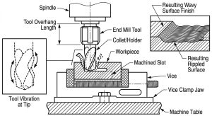
Chatter and vibration usually come from insufficient rigidity, whether that is excessive tool length, a thin-walled workpiece, or a loose fixture. Reducing stickout, increasing clamping stiffness, or adjusting spindle speed to move away from a resonant frequency all help. Sometimes simply slowing the feed rate settles the vibration enough to finish the job.
Tool breakage often follows excessive radial or axial engagement, a feed rate mismatched to the tool’s flute count, or a worn cutting edge that is no longer shearing cleanly. Checking that the programmed parameters match the tool manufacturer’s recommendations, and replacing tools before they reach the end of useful life, prevents most breakages.
Excessive heat points to rubbing rather than cutting, insufficient coolant, or cutting speeds set too high for the material. Confirming chip formation looks correct, rather than dust or smearing, is a quick diagnostic. Reducing speed, increasing feed, or improving coolant delivery usually resolves it.
Poor chip evacuation or packing shows up as re-cut chips, poor surface finish, or sudden tool failure in deep slots and pockets. Reducing depth of cut per pass, adding peck cycles, or increasing coolant pressure to physically flush chips out of the cut all address this directly.
FAQs
Can End Mills Drill Holes?
Some end mills, particularly those with a centre-cutting design, can plunge directly into material like a drill and start a hole from solid. Not all end mills are centre-cutting, though, so this depends on the specific tool. Even when possible, a dedicated drill is usually faster and more efficient for producing a simple round hole.
Can End Mills Be Sharpened?
Yes. End mills, particularly solid carbide ones, can be resharpened by regrinding the cutting edges, which restores much of their original performance at a fraction of the cost of a new tool. Coated tools generally need recoating after regrinding to maintain wear resistance, and there is a limit to how many times a tool can be reground before its geometry or diameter drifts out of tolerance.
Is End Milling Accurate?
Modern CNC end milling holds tolerances in the range of a few thousandths of a millimetre on well-maintained machines with rigid setups, which is accurate enough for aerospace, medical and precision tooling work. Actual achievable accuracy depends on machine condition, tool quality, workholding and thermal stability, so it varies from shop to shop and job to job.
How Deep Can an End Mill Cut per Pass?
This depends on tool diameter, material and rigidity, but a common rule of thumb for roughing is a depth of cut around 0.5 to 1 times the tool diameter in easier materials like aluminium, dropping to a fraction of that in harder materials like stainless steel or titanium. Finishing passes are almost always much shallower, often well under a millimetre, since the goal there is surface quality rather than material removal rate.
