

 EU
Face milling is how most shops produce the flat face that almost every machined part needs, whether to locate in a fixture, seal against a gasket, or mount to another component.
The same face mill can clean up a cast housing in a few passes, or leave chatter marks, burred edges, and a surface that fails flatness inspection. The difference comes down to four choices: the cutter, its entering angle, where it sits on the part, and the feed per tooth.
This guide explains each one, along with the process, cutter types, and trade-offs.
What Is Face Milling?
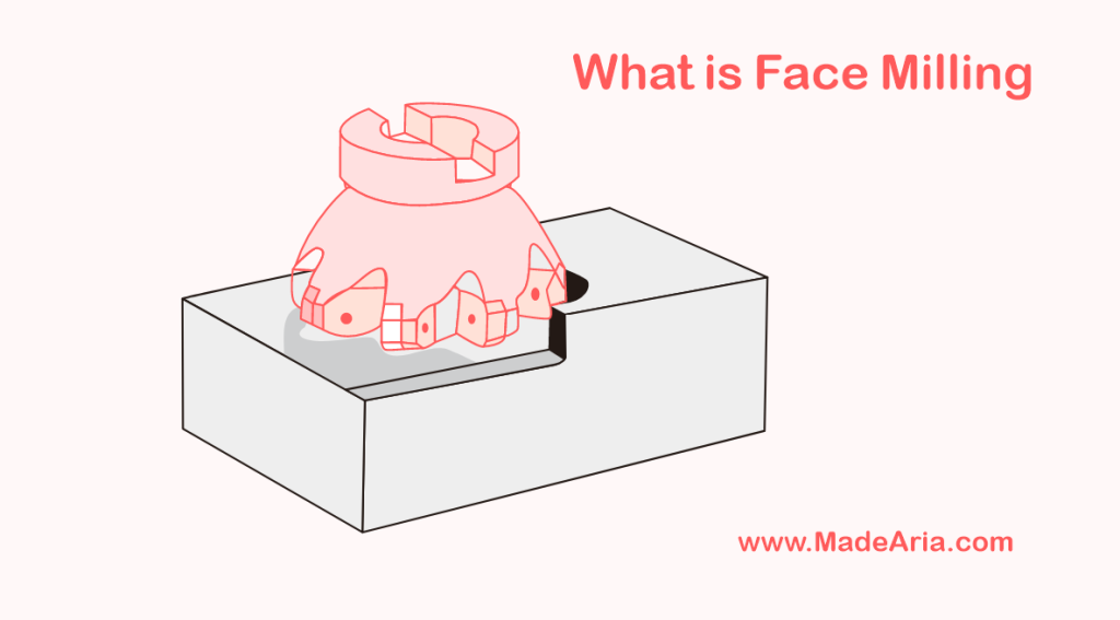
Face milling is a machining process that cuts a flat surface on the top of a workpiece using a rotating cutting tool, usually fitted with multiple inserts, with the tool axis perpendicular to the workpiece surface. It is the standard method for flattening, squaring, and finishing large surfaces on CNC milling machines and machining centers.
The cutter uses two sets of edges. The main cutting edges, at the outer corner of each insert, cut to depth and remove most of the material. The short edges on the bottom face pass over the new surface and produce the final finish. The result is a flat face with curved, overlapping tool marks left by the cutter’s rotation and feed.
How the Face Milling Process Works
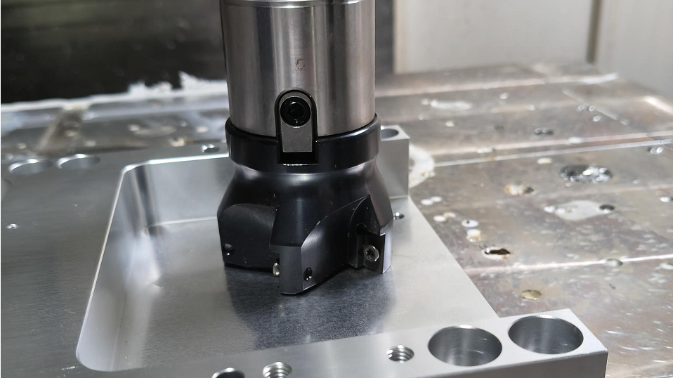
Face milling follows six steps: set up the workpiece, select the cutter, position the cutter and plan the tool path, set the cutting parameters, remove the material, and inspect the surface.
1. Set Up the Workpiece
Clamp the part in a vise or fixture so it sits flat and cannot move. Support the area under the face being cut. Thin or unsupported sections deflect during cutting and measure out of flat once unclamped.
2. Select the Cutter
Choose the cutter type based on the workpiece material, stock to remove, and required finish. A 45° indexable face mill suits most general work. Size the cutter 20 to 50% larger than the width of cut for a stable cut.
3. Position the Cutter and Plan the Tool Path
- Offset the cutter from the part centerline: On center, the radial force on each insert reverses direction and causes vibration. An offset that makes most of the cut climb milling also improves chip formation, giving a thin chip at exit that reduces burrs.
- Roll into the cut on an arc: A gradual entry reduces impact on the cutting edges, extending tool life.
- Keep the cutter engaged: Avoid crossing holes and slots, since each re-entry is a new impact on the inserts.
- Overlap passes on wide faces: A stepover of about 70 to 80% of the cutter diameter prevents uncut ridges.
4. Set the Cutting Parameters
Take spindle speed and feed per tooth from the insert supplier’s data for the workpiece material. Set depth of cut based on stock allowance and machine power.
5. Remove the Material
Take one or more roughing passes to remove most of the stock. On castings, cut below the hard outer skin on the first pass. Finish with a light, even pass to set the final dimension and surface.
6. Inspect the Surface
Check flatness, dimensions, and surface roughness against the drawing before unclamping the part. If the surface shows chatter or uneven tool marks, review the setup, cutter position, and insert condition.
Main Types of Face Milling Cutters
Face milling cutters are classified by construction and by entering angle.
By Construction
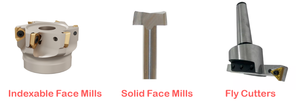
- Indexable Face Mills: An indexable face mill holds replaceable carbide milling inserts in a steel body. Worn edges are rotated or replaced while the body stays in use, which makes indexable face mills the standard choice for both roughing and finishing in production. Larger sizes use a shell mill mount, fitted onto an arbor with drive keys and a center bolt.
- Solid Face Mills: A solid face mill is made in one piece from carbide or high-speed steel. Solid face mills suit small faces, low-power machines, and tight spaces. When worn, the whole cutting tool must be reground or replaced.
- Fly Cutters: A fly cutter is a face milling tool that holds a single point cutting tool in a rotating body. Fly cutters are cheap and leave a fine finish, but one cutting edge means slower material removal, so they are too slow for production. They are common for prototypes and machining softer materials such as aluminum.
By Entering Angle
The entering angle (κr) of a face milling cutter, also called the cutting edge angle, is the angle between the main cutting edge and the machined surface. US catalogs use lead angle instead, measured from the cutter axis, so a 90° entering angle equals a 0° lead angle. A smaller entering angle makes the chip thinner, known as the chip thinning effect (hex = fz × sin κr), and sends more cutting force axially into the spindle.
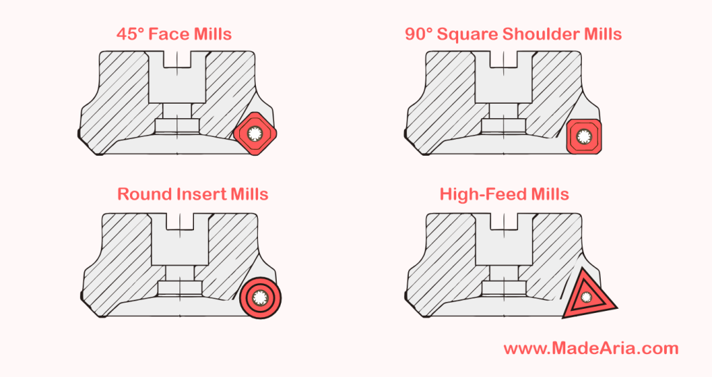
- 45° Face Mills: A 45° face mill is the standard choice for general face milling. Its chip is about 0.71 × fz, its balanced forces give a smooth cutting action, and it reduces exit burrs. A 45° face mill cannot cut a 90° shoulder.
- 90° Square Shoulder Mills: A 90° square shoulder mill cuts a flat face and a square wall in one pass. Its chip equals fz, so the feed must be lower than with a 45° face mill. Its mostly radial force suits thin floors that would bend under axial load, but exit burrs are more likely.
- Round Insert Mills: A round insert face mill has an entering angle that changes with depth of cut. The round edge is the strongest insert shape, so round insert cutters suit titanium, heat-resistant alloys, and heavy roughing. They leave a corner radius at the shoulder.
- High-Feed Mills: A high-feed face mill, used for high feed milling, has an entering angle of about 10°, which makes the chip only about 0.17 × fz. This allows a feed per tooth several times higher than a 45° face mill. Axial force keeps the cut stable with long tool overhang, but depth of cut is shallow and a finishing pass is needed.
Types of Face Milling Operations
The four main types of face milling operations are conventional, partial, roughing, and finishing face milling. The first two describe how the cutter covers the part. The last two describe the purpose of the pass.
Conventional Face Milling
Conventional face milling uses a cutter wider than the workpiece, so the cutter overhangs the part on both sides and cuts the full width in one pass. It is the standard way to flatten plates, blocks, and housing faces. The name refers to cutter coverage, not to conventional (up) milling direction.
Partial Face Milling
Partial face milling uses a cutter that overhangs the workpiece on one side only. It is used for narrow faces along an edge, faces next to a shoulder, and wide faces that need several passes. The radial force pushes the part to one side, so the fixture must resist that load. When less than half the cutter diameter is engaged, the chip gets thinner and the feed can be raised.
Roughing Face Milling
Roughing face milling, sometimes called heavy-duty face milling, removes most of the stock with a large depth of cut, a high feed, and tough inserts. Its limit is usually machine power and setup rigidity, not the cutter. Roughing face milling leaves a small, even allowance for the finishing pass.
Finishing Face Milling
Finishing face milling uses a light cut to achieve the required dimensions and surface finish. Wiper inserts can allow up to twice the feed rate without sacrificing surface quality under suitable conditions. Typical surface roughness may range from Ra 0.8 to 3.2 µm (32 to 125 µin), depending on the material, tooling, and cutting parameters.
Are Climb Milling and Slotting Types of Face Milling?
No. Climb milling and conventional milling describe cutting direction, not a face milling operation. In climb milling, also called down milling, the cutter rotates in the same direction as the feed at the point of contact. A face mill does both climb and conventional milling in every pass. When the cutter overhangs the part on both sides, the inserts climb mill on one side of the cutter centerline and conventional mill on the other. The cutter offset sets the ratio between the two, which is why an offset toward climb milling gives a thinner chip at exit.
Slotting and contour milling are not face milling operations either. They cut with the side of the tool and are done with end mills, as covered in the comparison section below.
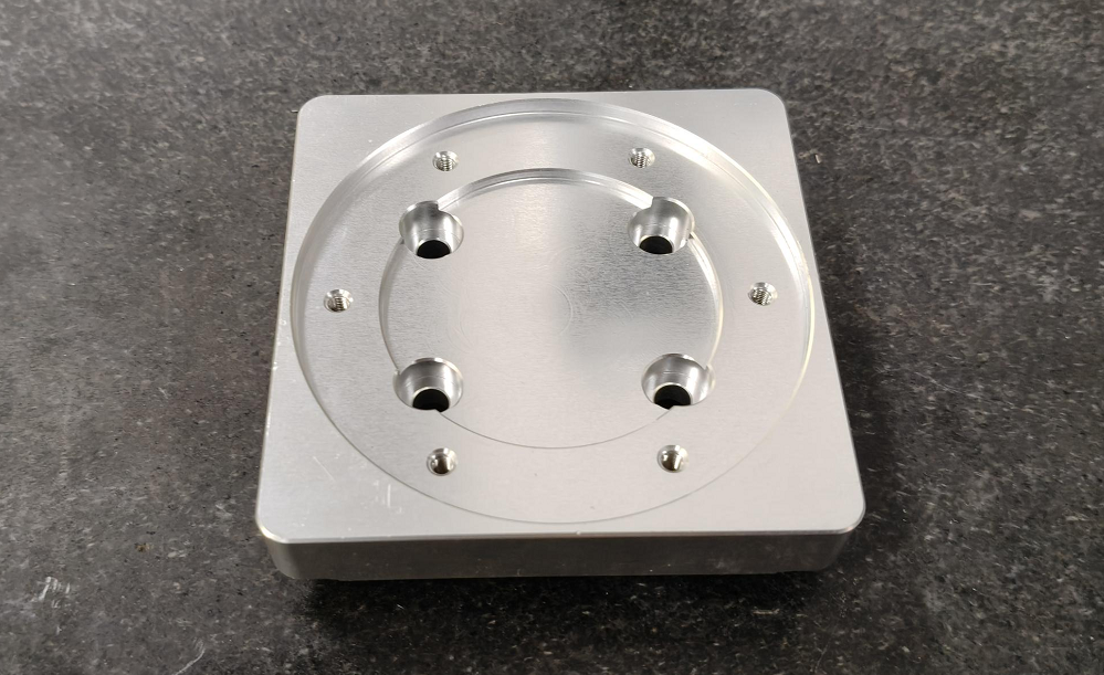
Key Parameters of Face Milling
Face milling results depend on four parameters: cutting speed, feed rate, depth of cut, and width of cut. Together, they set the cycle time, surface quality, and cutting forces on the cutter and part. Starting values come from the insert supplier’s data for the workpiece material and are then adjusted from test cuts.
- Cutting speed is the speed of the cutting edge through the material, in m/min or SFM. It depends mainly on the work material and insert grade. Aluminum runs much faster than steel, and titanium much slower. Too high a speed accelerates tool wear.
- Feed rate is the table feed, calculated as vf = fz × z × n, where fz is feed per tooth, z is the number of inserts, and n is spindle speed. A higher feed shortens cycle time, while feed per revolution sets the surface finish.
- Depth of cut, or cutting depth, is how deep the cutter goes in one pass. Roughing uses deeper cuts. Finishing uses a light, even cut to set the final size and finish.
- Width of cut is how much of the cutter diameter engages the part. About 65 to 85% of the cutter diameter gives a stable cut.
Advantages and Limitations of Face Milling
Face milling is usually the fastest way to produce large, flat, smooth surfaces. Its main limits are that it only makes flat surfaces and needs a rigid, well-powered setup.
Advantages of Face Milling
- Fast material removal on large surfaces: A face mill carries many inserts and covers a wide path, so it removes material quickly and clears large faces in few passes.
- Good flatness and surface finish: With wiper inserts and a stable setup, face milling often reaches the final finish without grinding and leaves a reliable datum for later operations such as drilling and pocket milling.
- Low cost per part in production: Indexable inserts have multiple cutting edges each, and only the inserts are replaced when they wear.
- Works on most machinable materials: Steel, stainless steel, cast iron, aluminum, titanium, and plastics can all be face milled with the right insert grade and proper insert geometry.
Limitations of Face Milling
- Flat surfaces only: Face milling cannot cut pockets, slots, internal corners, or 3D contours, and a large cutter cannot reach faces beside tall walls. These features need end mills.
- Higher upfront tooling cost: A face mill body and inserts cost more than a solid end mill, though the cost per part drops over a production run.
- Needs a rigid machine and enough power: Weak workholding or a low-power spindle causes chatter marks and poor flatness. Choosing a smaller cutter or a high-feed design reduces the load.
- Burrs and edge chipping at the exit: Burrs and chipped edges can form where the inserts leave the part, especially in cast iron. A 45° cutter and a thin exit chip keep this under control.
Face Milling Vs Other Milling Operations
Face milling, peripheral milling, and end milling can all produce flat surfaces. They differ in cutter orientation and in which edges do the cutting.
Face Milling vs. Peripheral Milling
In face milling, the cutter axis is perpendicular to the machined surface. In peripheral milling, also called slab or plain milling, the cutter axis is parallel to the surface, and the teeth on the outer diameter do the cutting. Face milling is faster on wide surfaces and gives better flatness and finish, while peripheral milling suits narrow faces, side walls, and profiles. For a detailed breakdown, see the guide on peripheral milling vs face milling.
Face Milling vs. End Milling
Face milling uses a large, multi-insert cutter to flatten wide, open surfaces quickly. End milling uses a smaller cutter that cuts with both its side and its end, so it can produce pockets, slots, shoulders, and contours that a face mill cannot reach. For a full comparison of tools and applications, see the guide on face milling vs end milling.
Conclusion
Face milling is the standard method for machining flat surfaces on metal and plastic parts. Good results come from a few key choices: the right cutter and entering angle, an offset cutter position, and cutting data matched to the material. With these in place, a single setup can deliver a flat datum, a clean finish, and a short cycle time.
Need Precision Face-Milled Parts?
Aria Manufacturing provides CNC machining for metal and plastic parts, from prototypes to production runs. Projects are supported by the factory in Dongguan, China, and the European office in Denmark. Send your drawings to get a quote.
