

 EU
Most features on a machined part, from slots and pockets to 3D contours, are cut by end milling. How the process is run decides part cost, lead time, and whether the part holds tolerance. This guide helps engineers, designers, and buyers understand the process, avoid common machining problems, and work better with suppliers.
What is End Milling?
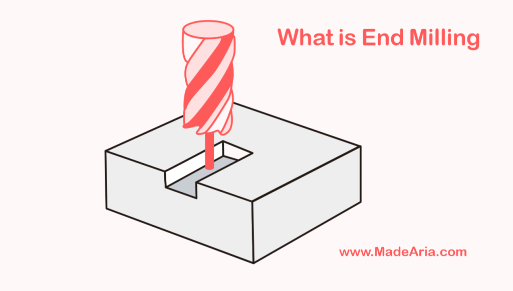
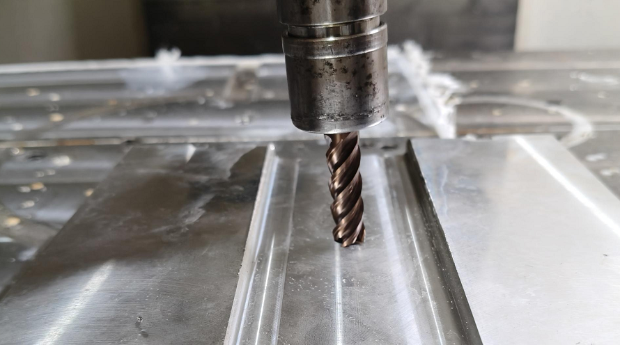
End milling is a CNC machining process in which a rotating end mill removes material using cutting edges on both the tip and the sides. The tool can plunge into the part and then move sideways, so it forms slots, pockets, shoulders, profiles, and 3D contours. A drill bit with a pointed tip only makes round holes, and face milling only flattens surfaces.
The name comes from the milling tool itself, which cuts with its end as well as its sides. The process runs on CNC milling machines and machining centers and works on most machinable metals, plastics, and composites.
How End Milling Works
End milling starts with the workpiece clamped firmly in a vise or fixture on the machine table. The end mill is held in the spindle and spins at a set speed. The CNC program then moves the tool or the table along the X, Y, and Z axes. As the tool feeds into the part, each flute shears off a thin layer of material as a chip. The bottom edges cut down to set the depth and form floors, while the side edges cut walls, shoulders, and profiles.
The helical flutes lift the chips up and out of the cut, carrying much of the heat with them. Coolant or compressed air helps clear the chips and keep the tool cool. Spindle speed, feed rate, depth of cut, and toolpath are all set in the CNC program, and together they decide the part’s accuracy, surface finish, and tool life.
Structure of End Mills
An end mill has four main features. Each one affects how the tool cuts and how long it lasts.
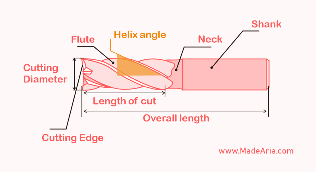
- Shank: The non-cutting part clamped in the tool holder. It keeps the tool centered and rigid during cutting. The shank diameter must match the collet or tool holder.
- Neck: A reduced-diameter section between the shank and the flutes on some end mills. It gives clearance when cutting deep features.
- Flute: The spiral grooves along the tool body. They form the cutting edges and carry chips out of the cut.
- Cutting edge: The sharp edges along each flute and across the tip. Side edges cut walls and profiles. End edges cut floors and let the tool enter the material.
- Helix angle: The angle between the flute and the tool axis. It affects cutting smoothness, chip flow, and edge strength.
Types of End Mills
End mills are mainly classified by the shape of their cutting end. The shape decides which features the tool can cut. The most common types are
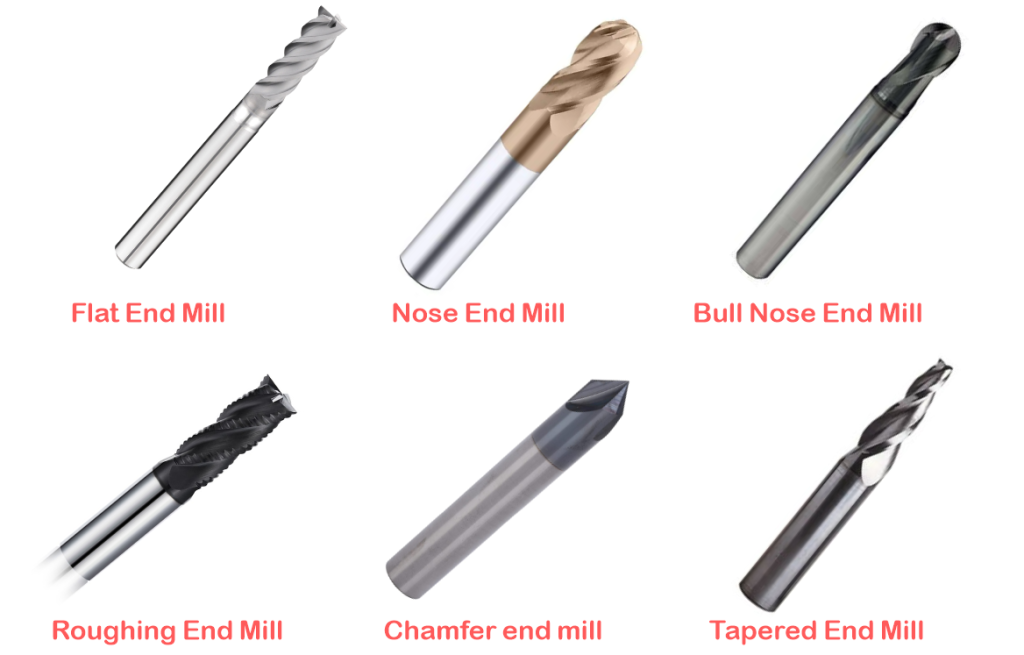
- Square (flat) end mill: Flat tip with sharp 90° corners. Used for slots, pockets, shoulders, and flat-bottom features.
- Ball nose end mill: Also called a ball end mill. Rounded tip for 3D contours, curved surfaces, and mold cavities.
- Corner radius (bull nose) end mill: Flat tip with rounded corners. Stronger than a square tip and leaves a fillet at the base of walls.
- Roughing end mill: Serrated edges that break chips into small pieces for fast material removal.
- Chamfer end mill: Angled edges for beveling and deburring part edges.
- Tapered end mill: Edges that narrow toward the tip, used for angled walls and draft features in molds.
End mills also differ in construction. Solid end mills are made from one piece of carbide or high speed steel (HSS). They typically range from about 0.5 mm to 25 mm in diameter and suit small features and precision work. Indexable end mills hold replaceable carbide inserts on a steel body. They are available in much larger diameters, some over 100 mm, which makes them cost effective for heavy roughing.
How to Choose the Right End Mill
The right end mill depends on the workpiece material and the feature being cut. Five factors matter most.
- Flute count: The number of flutes sets chip room and strength. 2 or 3 flutes leave more room for chips and suit aluminum, plastics, and slotting. 4 or more flutes add tool strength and give a finer finish for steel, harder materials, and finishing operations.
- End mill material and coating: Carbide end mills can run at several times the cutting speed of HSS and are the standard for CNC work. HSS suits soft materials and lower cutting speeds. TiN, TiAlN, or AlTiN coatings help with steel, stainless steel, and titanium. Uncoated or DLC-coated carbide works best for aluminum and plastics.
- Helix angle: A helix of around 30° gives a strong edge for steel and general work. A higher helix of 40° to 45° cuts more smoothly and clears chips faster in aluminum. A variable helix reduces chatter.
- Center-cutting: Only a center-cutting end mill can plunge straight down into solid material. Choose one for closed pockets. Non-center-cutting tools must ramp in or start from an open edge or pre-drilled hole.
- Length: Choose the shortest overall length that reaches the full feature depth. Longer tools bend more, which causes chatter and poor finish. A reduced-neck tool gives reach for deep pockets while staying rigid.
Types of End Milling Operations
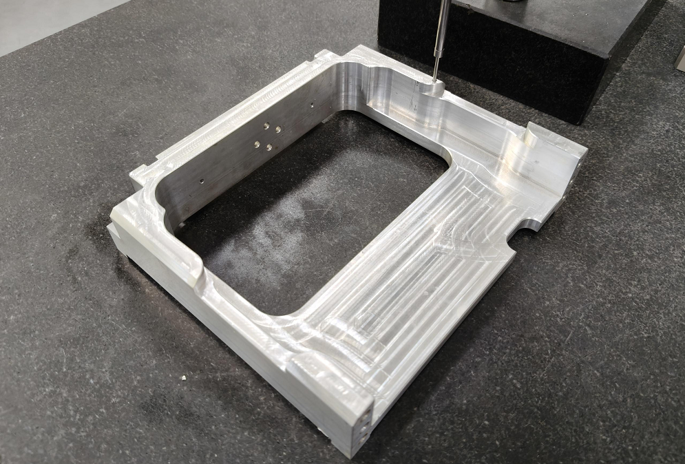
End mills are versatile tools. The same end mill can cut different features depending on the toolpath. The most common operations are:
- Slotting: Cuts a straight channel using the full cutter diameter, so a 6 mm end mill cuts a 6 mm wide slot. It puts the highest load on the tool. A common starting point is a depth of cut no more than half the tool diameter, along with good chip clearing.
- Pocket milling: Clears material inside a closed boundary to form a recess. The inside corners always take the tool radius, so sharp internal corners cannot be milled.
- Profiling and contouring: Profiling cuts the outer or inner outline of a part. Contouring follows curved 3D surfaces, usually with ball end mills.
- Side (shoulder) milling: Cuts a vertical wall, or a wall and the floor next to it, to form a step.
- Plunging and ramping: Plunging feeds the tool straight down and needs a center-cutting end mill. Ramping enters at an angle or in a spiral, which lowers the load on the tip.
Climb vs. Conventional Milling
Climb and conventional milling describe the direction of tool rotation relative to the feed. They apply to all the operations above.
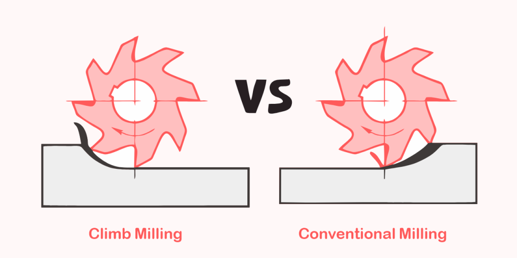
- Climb milling (down milling): The tool rotates in the same direction as the feed. Each chip starts thick and ends thin. This reduces rubbing and heat, helps extend tool life, and gives a better surface finish. It is the default on modern CNC machines.
- Conventional milling (up milling): The tool rotates against the feed. Each chip starts thin and ends thick, so the edge rubs before it cuts. It is still used on manual machines with leadscrew backlash and on castings or forgings with a hard outer skin.
For a full comparison of when to use each method, read our guide on climb vs. conventional milling.
Advantages and Disadvantages
End milling is the most flexible way to cut features into a part, but it is not always the cheapest or fastest. The points below help you decide when it fits your project and when another process may be better.
Advantages
- Versatile: One tool can cut slots, pockets, profiles, shoulders, and 3D contours, often in a single setup, which improves machining efficiency.
- Handles complex shapes: On 3-, 4-, and 5-axis machines, end mills follow curved surfaces and deep cavities that other cutting methods cannot reach.
- High precision: CNC control produces accurate parts and repeats the same result on every part in a batch.
- Good surface finish: With finishing end mills and the right parameters, walls and floors often need no secondary polishing.
- Wide material range: With the right tool, it cuts aluminum, steel, stainless steel, titanium, plastics, and composites.
Disadvantages
- Tool wear and cost: Hard and abrasive materials wear end mills quickly, and high-performance carbide tools are costly to replace.
- Skill required: Tool selection, toolpath programming, and setup all affect the result, so complex parts need experienced machinists.
- Limited depth: Tool length limits how deep the tool can cut. Deep, narrow pockets need long tools, which are less accurate and slower to run.
- Slow on large flat areas: End mills have lower material removal rates than face mills on wide surfaces.
- No sharp internal corners: The round tool always leaves a radius in inside corners. Sharp corners need EDM or another secondary process.
Industry Applications
End milling is used wherever parts need slots, pockets, profiles, or 3D surfaces. It is especially useful when one part has many features that can be cut in a single setup.
- Aerospace: Structural ribs, brackets, housings, and turbine blades in aluminum and titanium.
- Automotive and EV: Engine and transmission housings, brake calipers, battery trays, and motor components.
- Medical: Surgical instruments, orthopedic implants, fluid manifolds, and device housings in titanium, stainless steel, and PEEK.
- Electronics: Enclosures, EMI shielding covers, heat sinks, and sensor housings with fine pockets and thin walls.
- Mold and die: Core and cavity inserts, electrodes, and complex 3D mold surfaces.
- Industrial equipment: Hydraulic manifolds, fixtures, jigs, and machine components with keyways and precision slots.
Common Problems
Most end milling problems trace back to four causes. Each one shows clear signs on the part and has a known fix.
- Chatter: Vibration leaves a wavy pattern on the surface and a high-pitched noise. It usually comes from long tool stick-out, weak clamping, or too heavy a cut. Shorten the tool, clamp the part more rigidly, reduce the depth or width of cut, or adjust the spindle speed. A variable helix end mill also helps.
- Tool runout: When the tool does not spin on its true center, one flute does most of the cutting. This causes oversized features, a poor finish, and early wear. Clean the collet and holder, replace worn collets, and use precision holders for tight-tolerance work.
- Tool breakage: Tools break from excessive feed or depth, packed chips, straight plunging with the wrong tool, or sudden load in corners. Follow the supplier’s recommended parameters, ramp into the material, use toolpaths with steady engagement, and replace tools before they wear out.
- Poor chip evacuation: Chips trapped in deep slots and pockets get recut, which raises heat and can break the tool. Use fewer flutes for soft materials, direct coolant or air at the cut, and machine deep features in several shallower layers.
Conclusion
End milling cuts most of the features on a machined part, from simple slots to complex 3D surfaces. The result comes down to three choices: the right end mill for the material and feature, the right operation, and a setup that keeps chatter and chip buildup under control. Small design decisions matter too. Adding a radius to internal corners and avoiding unnecessarily deep pockets can reduce machining time and cost.
If you are not sure how a feature on your drawing will be machined, or which details drive the cost, Aria’s engineers can review your CAD files and suggest changes before production.
