

 EU
EUFace milling is one of the most common machining operations in CNC machining. It turns a rough casting or a welded plate into a flat, accurate reference surface. This guide covers how the face milling process works, the parameters and tooling choices that affect results, and how it compares with peripheral milling and end milling.
What Is Face Milling?
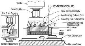
Face milling is a machining process that produces flat surfaces on a workpiece, using multiple cutting edges arranged around the face of a rotating cutter. The cutter axis sits perpendicular to the workpiece surface, which separates it from peripheral milling, where the cutter’s side does the work instead. The goal is to create flat, accurate reference planes, often cut as the first step on a raw casting or forging, or as a finishing pass where surface quality matters most.
How Does Face Milling Work?
1. Setup and Securing
The workpiece is mounted onto the machine bed using vices or clamps. Firm clamping matters here, since any movement during a heavy cut throws off flatness and can damage the insert. Thin walled components need extra care, since a weak setup increases tool deflection and can distort the part under load.
2. Tool Rotation
On CNC milling machines, the spindle drives the cutter body, turning the indexable inserts at the speed set for the workpiece material and insert grade.
3. Axis Engagement
The cutter axis is aligned at ninety degrees to the top of the workpiece, so the flat face of the cutter sits parallel to the surface as it engages the material at a set cutting depth. Cutter diameter and insert count together determine how much of the surface each pass covers.
4. Material Removal
The workpiece feeds under the rotating cutter along a planned tool path. Each insert takes its share of the load in turn, and proper chip evacuation keeps loose material from being recut across the machined surface. Any wiper inserts trailing behind level out the feed marks left by the tool’s cutting edges.
Cutting Tool Materials (Carbide, HSS, Ceramic, CBN)
Carbide inserts handle most general steels, stainless steels and non-ferrous metals. High speed steel remains a lower cost, tougher option for slower speed jobs on less abrasive materials. Ceramic inserts hold up better under the heat generated during rapid roughing of nickel superalloys. Cubic boron nitride, or CBN, is used on hardened tool steel above 45 HRC, where carbide wears too quickly to be practical.
Applications of Face Milling
- Stock Preparation: Squaring the faces of raw blocks before detailed feature machining begins.
- Roughing Large Surfaces: Clearing high volumes of stock from structural plates and welded bases.
- Finishing Mating Faces: Producing flat joint faces on split gearboxes, pump housings and manifolds.
- Automotive Manufacturing: Machining reference surfaces on engine blocks, cylinder heads and transmission cases.
- Aerospace Engineering: Sizing structural spar caps, bulkheads and wing panels to a uniform thickness.
- Mould and Die Making: Flattening tool steel blocks before cavity work begins.
- General Industrial Manufacturing: Machining mounting bases, bedways and precision machinery plates.
Aria machines flat reference surfaces and mating faces across these applications, from prototype plates to production runs.
Types of Face Milling Operations
General Face Milling (45° Lead Angle)
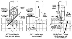
A 45° lead angle balances the axial and radial cutting forces generated during the cut. This lowers the load on the spindle and bearings while still allowing high feed rates on steel and aluminium components.
Round Insert / Heavy-Duty Milling
Heavy stock removal on rough castings or forgings usually calls for round insert cutters rather than a cutter with a single fixed lead angle. As a round insert engages the material, its effective lead angle changes continuously through the cut, which spreads the load progressively and resists edge chipping on an uneven stock allowance.
High-Feed Milling (10° Lead Angle)
High feed cutters use a shallow lead angle, typically between 10° and 20°, to create the chip thinning effect for a given feed per tooth. This lets the machine run at high feed rates while keeping the depth of cut shallow, usually under 3 mm.
Fine Finishing with Wiper Inserts
Wiper inserts sit slightly lower in the cutter body than the main cutting inserts. Within the same rotation, the wiper trails behind the roughing inserts and flattens the feed marks they leave, producing a fine finish, often Ra 0.4 to 0.8 µm, without a separate grinding step.
Types of Face Milling Cutters
Primary Cutter Types (Shell Mills, Indexable Face Mills, Fly Cutters)
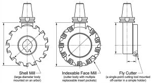
Shell mills mount on an arbor and suit broad surfaces on larger parts. Indexable face mills use quick-change carbide inserts, which keeps tool changeover fast and running costs down. Fly cutters use a single point tool bit, which limits material removal rate but produces a good finish at low cutting force, useful on lighter machines.
Insert Geometries and Lead Angles (45° vs. 90°)
The lead angle is chosen to match the operation rather than the material alone. A 45° lead angle spreads the cutting load over a longer edge length, which protects the insert corner and suits general facing work. A 90° lead angle directs the force radially instead, producing a square shoulder where the flat face meets a vertical wall. If the part needs a sharp internal corner, a 90° cutter is the only real option. If the job is open facing with no adjoining wall, a 45° cutter usually runs faster and puts less strain on the insert.
Key Process Parameters for Face Milling
Three formulas connect the core variables and are worth keeping on hand when setting up a job:
- Spindle speed: n = (Vc × 1000) / (π × Dc)
- Table feed rate: Vf = fz × z × n
- Material removal rate: Q = (ap × ae × Vf) / 1000
Where Dc is cutter diameter (mm), z is the number of inserts, n is spindle speed (rpm), and Q is given in cm³/min.
Cutting Speed (Vc) and Feed Rate (fz)
Cutting speed is the surface speed of the rotating insert, set according to the workpiece material and insert grade. Feed rate per tooth governs the thickness of each chip. Too low, and the insert rubs rather than cuts, which accelerates tool wear. Too high, and the load on each edge increases, which can chip the insert. See the reference table below for typical ranges by material.
Cutting Parameter Reference by Material
The ranges below are general starting points for carbide inserts. Always check the specific insert grade’s data sheet before programming, since coating, geometry and machine rigidity all shift the usable window.
| Material | Vc (m/min) | fz (mm/tooth) | Typical insert |
| Aluminium | 400 – 1,200 | 0.10 – 0.30 | Carbide, uncoated or PVD |
| Carbon / low alloy steel | 150 – 300 | 0.10 – 0.25 | Carbide, PVD or CVD coated |
| Stainless steel | 90 – 170 | 0.08 – 0.20 | Carbide, PVD coated |
| Cast iron | 150 – 270 | 0.15 – 0.35 | Carbide, CVD coated |
| Titanium alloys | 35 – 60 | 0.05 – 0.15 | Carbide, PVD coated |
| Hardened steel (>45 HRC) | Material-dependent, generally well below softer steels | 0.05 – 0.15 | CBN or ceramic |
Depth of Cut (ap) and Width of Cut (ae)
Depth of cut (ap) is the axial engagement of the insert into the material. Finishing passes typically run between 0.25 mm and 0.5 mm, while heavy roughing can exceed 10 mm. Width of cut (ae) is the radial engagement of the cutter across the part face, usually expressed as a percentage of cutter diameter (Dc) rather than as an overlap between passes. Keeping ae at around 60 to 80% of Dc, depending on the cutter manufacturer’s recommendation, tends to balance chip formation and insert load well for both roughing and finishing.
Insert Selection and Performance Coatings
Insert choice depends on workpiece hardness, ductility, and whether the pass is roughing or finishing. Coating follows a similar logic. PVD coatings give a sharper edge, suited to sticky non-ferrous metals and stainless steel. CVD coatings provide a thicker thermal barrier, better suited to dry machining of cast iron and carbon steel.
Advantages of Face Milling
Exceptional Productivity and High Material Removal Rates
- Broad engagement: Wide contact between the cutter and workpiece clears stock quickly across broad faces.
- Higher feed rates: Shallow lead angles allow faster feeds without overloading the insert.
- Faster tool changes: Indexable inserts let the operator rotate a worn edge rather than replace the whole cutter body.
Superior Surface Finish and Flatness Accuracy
- No secondary step needed: Multi-insert cutters, combined with a wiper pass, produce a flat surface without extra finishing.
- Accurate downstream work: A flat, perpendicular base plane established early makes hole placement more accurate.
- Consistent finish: Good insert alignment keeps Ra consistent across the whole face.
Optimised Cutting Mechanics and Tool Longevity
- Stable cutting forces: Forces push the workpiece down into the fixture rather than sideways.
- Extended tool life: Spreading the load across several rotating inserts reduces thermal stress on any single edge.
Machining Versatility and Process Reliability
- Wide material range: Face milling handles non-ferrous alloys, structural steels and superalloys with the same basic tooling.
- Standard tooling: Cutter bodies and inserts are widely available as standard items.
- Scalable process: Runs on equipment from small vertical mills to large CNC gantry machines.
Disadvantages of Face Milling
Geometric and Design Limitations
- Flat surfaces only: Cannot cut internal pockets, curved shapes or complex three-dimensional contours.
- Limited reach: A wide cutter body cannot reach into narrow channels or deep recesses.
- Needs other processes: Angled surfaces call for angular face milling, while slots and vertical walls need plain milling.
Operational and Mechanical Limitations
- Rigidity required: Needs a rigid spindle and a solid fixture to handle the cutting forces.
- Vibration risk: A weak setup increases tool deflection and shows heavy vibration marks.
- Edge damage: High edge pressure can chip or burr the corners where the tool exits the cut.
Tooling and Capital Cost Penalties
- Higher upfront cost: Large indexable cutter bodies and carbide insert packs cost more than simpler tooling.
- Precision alignment needed: Each insert must be aligned carefully to avoid height runout.
- Higher power demand: Driving a wide cutter through tough material needs more spindle torque and power.
Face Milling vs. Peripheral Milling
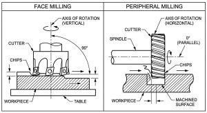
Face milling and peripheral milling differ in tool orientation and in what they are best suited to cut.
| Feature | Face Milling | Peripheral Milling |
| Tool axis orientation | Perpendicular to workpiece surface | Parallel to workpiece surface |
| Primary cutting edges | Insert corners and bottom face | Outer circumference teeth |
| Main application | Broad flat faces, reference planes | Slots, side steps, profile contours |
| Force direction | Mainly axial, into the spindle | Mainly radial, against the tool shank |
| Surface finish | Smoother, aided by wiper action | More exposed to deflection marks |
Cutter position relative to the workpiece centreline matters more than feed direction alone. A cutter centred over the workpiece cuts in climb mode on one side and conventional mode on the other within the same rotation, which produces the sharpest impact as each insert enters and exits the cut. Offsetting the cutter to one side controls the chip thickness at entry, which has a bigger effect on insert life and flatness than the choice between climb and conventional feed.
Face Milling vs. End Milling
Both operations can produce a flat surface, but they suit different jobs.
| Feature | Face Milling | End Milling |
| Coverage per pass | Diameter usually spans most or all of the part width | Narrower diameter, needs many overlapping passes |
| Cycle time on large surfaces | Generally faster, fewer passes at a comparable removal rate | Slower on wide areas due to overlapping passes |
| Feature flexibility | Limited to flat surfacing | Can face, cut pockets, and machine walls and slots with the same tool |
| Edge finish | Wiper insert gives a flatter, more consistent surface | Leaves a rounded corner at floor-to-wall transitions unless specified |
| Best suited for | Large, simple flat areas, fewer tool changes | Parts with mostly pockets and walls, only a small flat area |
Troubleshooting Common Face Milling Problems
| Symptom | Likely Cause | Fix |
| Chatter (wavy marks, harsh noise) | Excessive tool overhang, weak clamping, or spindle speed near a resonant frequency | Reduce overhang, increase clamping stiffness, or shift spindle speed slightly |
| Witness marks / repeating feed lines | Insert height variation between inserts (runout) | Check and reset insert seating, or verify wiper insert height |
| Bright band or shiny variation across the surface | Uneven insert wear, one insert cutting more than the others | Rotate or replace the insert set together, not one at a time |
| Burr or chipping at the cut exit | High edge pressure as the insert exits unsupported material | Reduce feed near the exit, add a support chamfer, or adjust cutter offset |
| Poor flatness across the pass | Cutter not trammed square to the spindle axis, or fixture lifting under load | Check spindle-to-table squareness and re-verify workholding |
| Insert chipping on entry | Cutter centred over the workpiece, producing a thick chip at entry | Offset the cutter to one side to control entry chip thickness |
FAQs
What is face milling? Face milling is a machining process that produces flat surfaces on a workpiece using the face and edges of a rotating cutter, with the cutter axis perpendicular to the surface.
What is the difference between face milling and plain milling? Face milling cuts with the face and corners of the cutter to produce flat surfaces. Plain milling cuts with the outer circumference of the cutter, and is used for slots, vertical walls and profile features rather than flat top surfaces.
What is the difference between slab milling and face milling? Slab milling, a form of peripheral milling, uses a cylindrical cutter with its axis parallel to the workpiece to remove material along the side of the tool. Face milling uses a cutter perpendicular to the surface, cutting mainly with the bottom face and insert corners.
What is the difference between side milling and face milling? Side milling cuts a vertical face or step using the periphery of the cutter, with the tool axis parallel to that face. Face milling cuts the horizontal top surface of a part, with the tool axis perpendicular to it.
What surface finish (Ra) can face milling achieve? Roughing passes typically leave Ra 3.2 to 6.3 µm. A finishing pass with a wiper insert can reach Ra 0.4 to 0.8 µm without a secondary grinding step.
