

 EU
EUHave you ever tried to steady a wobbly table on a flat floor? That rocking is a real-world sign of something not being flat. In manufacturing, the same wobble causes leaks, poor fits, and uneven pressure.
Flatness GD&T is the tool that catches it. This guide covers the flatness symbol, the tolerance zone, how flatness works, and how to measure it.
What is Flatness in GD&T?
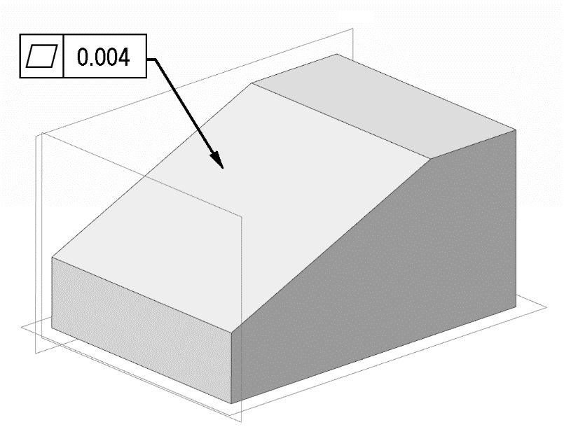
Flatness is a geometric tolerance that controls surface form. It is one of the fundamental form controls in GD&T, and its job is to keep a single planar surface as close to a perfectly flat plane as the design needs. In practice, a flatness tolerance defines the allowable waviness of that surface.
The key point is that flatness works alone. It needs no datum reference and ignores every other surface on the part. Controlling flatness means controlling the waviness of one specified surface, so every point on the actual surface sits inside a defined boundary. This kind of surface control goes further than a plain size dimension. A thickness dimension tells you how thick a plate is. It says nothing about whether the faces are flat. Flatness refines that by controlling form on its own.
Flatness Symbol

The flatness symbol is a parallelogram, a leaning square. It never sits on a drawing alone. It always goes inside a feature control frame, the control centre for the tolerance.
Feature Control Frame
The feature control frame is the rectangular box that carries a geometric tolerance on a drawing. Most frames have three compartments, the symbol, the tolerance value, and one or more datum references. Flatness is the exception. Because it applies to the whole surface and needs no datum, its frame has just two, the flatness symbol (▱) and the flatness tolerance value. That short, two-part frame is a quick way to spot a flatness control on a drawing.
Flatness Callout
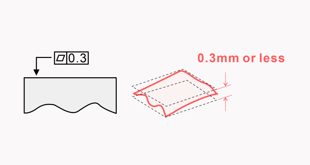
The flatness callout is the whole instruction, the frame plus the leader that points it at a surface. A callout of ▱ | 0.05 sets the tolerance at 0.05 units, millimetres or inches depending on the drawing, the total deviation allowed across the surface. It usually attaches to the surface or an extension line from it, since the common use controls a real face. For a large panel it can also be written per unit area, covered in the sheet metal section below.
Flatness Tolerance Zone
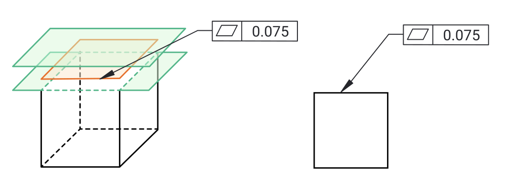
The tolerance zone is the most important idea in GD&T flatness. The ASME Y14.5 standard sets the rules for GD&T in North America. It defines flatness as a tolerance zone between two parallel planes within which the surface must lie, and ISO 1101 gives the same definition in the ISO system. That zone is a three-dimensional space, the flatness tolerance zone.
Picture two parallel planes, perfectly flat, held apart by the tolerance shown in the feature control frame. That gap is the specified tolerance zone. Every point on the physical surface must lie between those two parallel planes. The highest point cannot break through the top, and the lowest point cannot drop below the bottom. The surface is judged relative to that pair of planes, not to any other feature.
How to Measure Flatness in GD&T?
Measuring flatness is not a ruler job. It needs the right method and tools to read the surface form, and the goal each time is an accurate measurement of how far the surface strays from flat. Here are the common methods.
Surface Plate and Dial Indicator
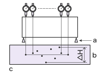
This is the classic method and probably the most common. It starts with a surface plate, a heavy granite slab with a very flat top, which acts as the reference once you set the part on it. You then run a dial indicator, sometimes called a dial gauge, across the surface. The total indicator movement, the full swing of the needle, is the maximum deviation and stands for the measured flatness. If it stays under the flatness tolerance on the drawing, the part is flat. A dial gauge check is cheap, quick, and good enough for many parts.
Using a Height Gauge and Surface Plate
This method also uses the surface plate as the reference, but with a height gauge. You can rest the part on three posts and move the gauge over it, or set the part on the plate and pass it under a fixed indicator. Either way you are looking for the total height difference across the surface. It is another clean way to turn flatness into a single number.
Using a CMM (Coordinate Measuring Machine)
Coordinate measuring machines use precise digital probing. The probe touches the surface in hundreds or thousands of spots and builds a point cloud. The software then creates virtual planes to test the flatness tolerance, running the minimum zone method to find the closest pair of parallel planes that still hold the whole cloud, giving a best fit plane for the data. This delivers a very accurate flatness result, and today it is the standard way to check flatness on serious parts.
Laser Interferometry
Laser interferometry gives the tightest results. It suits optics and high-precision parts that call for a tighter tolerance, reading interference patterns in laser light to catch height changes as fine as a nanometre. Laser scanning, one of these optical methods, can cover a surface without touching it, which helps on delicate parts. You would not use it on every part, but it is the right choice for a surface that must be flat to an extreme.
Flatness vs Other Characteristics
Flatness is easy to confuse with its close relatives. Knowing the differences lets you read drawings correctly and pick the right engineering tolerances.
Flatness vs Straightness
The easy split is what each one controls. Straightness works on a line. On a surface it checks whether single line elements run true, and on a feature of size it controls the derived median line, the axis of the feature. Flatness works on a whole surface in three dimensions.
A surface can hold straight line elements in every direction and still fail flatness, like a propeller blade that twists, and flatness catches that twist. Flatness can also apply to a feature of size, where it controls the derived median plane instead of the axis, but the surface case is by far the more common one.
Flatness vs Parallelism
This one turns on the datum. Parallelism is an orientation control, so it needs a datum reference and measures how parallel a surface is to a flat reference elsewhere on the part. Flatness needs no such thing, so a part can be perfectly flat and still sit at an odd angle. As long as it meets its flatness tolerance, it passes.
Flatness vs Surface finish
This is a scale comparison. Surface finish is the texture of a surface, the microscopic peaks and valleys, the feel of sandpaper. Flatness looks at the larger, wavier error that shapes the whole surface. Glass can be smooth yet gently domed. A road can be flat overall yet rough underfoot.
Flatness vs Size tolerancing
A size tolerance controls only the distance between two surfaces. A dimension of 10 mm ±0.1 mm tells you the part is thick enough but nothing about the shape of either face. Both faces could bow like a banana and still pass. Flatness controls surface shape separately, which matters when you track tolerance stacks and need parts to seat together.
When a surface also carries a size dimension, its flatness value has to stay smaller than the size tolerance, so flatness is always the tighter of the two. Where the joint is fussy, it does what a size tolerance cannot.
Benefits of Using Flatness Tolerance
So why go through all this trouble? What is the point of using a special flatness control? In the real world, applying flatness has some really big benefits. This geometric tolerance is very important in modern engineering and quality control. It helps make sure that parts fit together correctly and that manufacturing runs more smoothly. Let’s look at some of the main benefits.
1. Ensures proper mating of surfaces
When two surfaces meet to form a seal, like a gasket joint, or a stable base, they need to be flat. A flat mating face gives proper sealing and full contact, spreads the load, and cuts the stress concentrations that build at high spots. Without it you get leaks, wobble, and uneven wear.
2. Used in applying flatness to sheet metal parts
Sheet metal is hard to keep flat over a large area, and thin aluminium panels ripple easily. Forcing a whole panel to one tight value is slow and often impossible, so designers use a per-unit callout, for example 0.1 mm of flatness over any 25×25 mm area. This holds local flatness error in check without demanding higher flatness across the entire panel.
3. Improves the quality and consistency of the product
A clear flatness tolerance removes guesswork from the drawing and tells the maker exactly what the surface has to meet. Parts then come out consistent from batch to batch, which is the base of good quality control and matters for automated assembly.
Conclusion
Flatness GD&T can look like a minor mark on a busy drawing, but it is one of the most useful form controls you have. A simple flatness symbol inside a feature control frame sets up two parallel planes and a clear tolerance zone.
You can check it with a dial indicator on a surface plate, or reach for a coordinate measuring machine when you need the most accurate result. Because flatness needs no datum, it lets the designer control surface shape directly, which is why it stays a cornerstone of solid engineering.
FAQs
Q: Does flatness use maximum material condition or other material condition modifiers?
A: No. Flatness is a form control, and it applies regardless of feature size. Material condition modifiers such as maximum material condition go with features of size, not with a plain surface callout. The one related idea is the envelope principle, which links a feature’s size limits to its form, but that is separate from a flatness value.
Q: Can flatness control a derived median plane?
A: Yes, in one case. Applied to a surface, the common use, flatness controls the physical face. Applied to a feature of size, when the callout lines up with the size dimension, it controls the derived median plane instead, the centre points through the feature. The related control for the axis of a feature of size is straightness, which handles the derived median line.
Q: Does temperature affect a flatness measurement?
A: Yes. Thermal expansion can change a surface between a warm shop and a cool inspection room, so for tight work parts and gauges are left to settle at a stable temperature first. A part that is flat when cold may also distort when it heats up in service, and stress concentrations at high spots can make that worse.
Q: Which method gives the most accurate flatness reading?
A: For most parts a coordinate measuring machine gives the best mix of speed and accuracy, fitting a best fit plane to a point cloud. For the tightest work, optical methods like laser interferometry read interference patterns to catch nanometre changes.
