

 EU
EUOn a part whose curves and contoured edges keep shifting, how do you tell the shop floor exactly how far each slice of that shape may wander? That is the job the Profile of a Line does. It is the control engineers reach for when the shape of a single cross-section drives how a part performs, whether that slice is a straight edge, an arc, or one of the complex curves a modern part demands.
This guide walks through how it works, how its tolerance zone is built, how it differs from nearby callouts, how you measure it, and where it earns a place on a drawing.
What is Profile of a Line under GD&T?

The Profile of a Line is a form control in GD&T, a two-dimensional callout that sets a tolerance zone for a single line element on the surface of a part.
Picture one slice, a single cross-section cut through the part. This control tells you how far that one line, on that one slice, may vary from its ideal shape.
That ideal shape is called the true profile. Think of it as the flawless version of the line drawn from the CAD model or the engineering drawings. It is pinned down with basic dimensions, and although those basic dimensions carry no tolerance of their own, they establish the exact path the line should trace. That reference path is the ideal shape every measured slice is compared against.
From there, the Profile of a Line wraps a boundary around that ideal shape. The boundary is a pair of curves that run parallel to it, and the space between them is the line tolerance zone.
Every measured point along the real surface of the finished part, taken on that one cross-section, has to sit inside the tolerance zone. The control governs the shape of a line whether that shape is straight, an arc, a circle of some radius, or a far busier curve. In short, it makes sure the line elements of a feature stay true to the drawn shape.
Profile of a Line Tolerance Zone
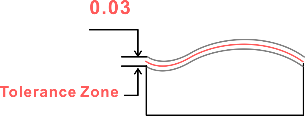
Let’s unpack that tolerance zone, since it is the thing you are really policing. Its makeup is simple: two parallel lines that follow the ideal path, held apart by the tolerance value written in the feature control frame.
Picture a road with two curbs. The center line is the ideal path, the curbs are the edges of the tolerance zone, and the measured surface has to stay on the tarmac between them.
The zone copies the shape of the ideal path exactly. If that path is an arc of a set radius, the boundaries become parallel curves of the same sweep. If the geometry gets busier, the tolerance zone follows every twist without complaint, giving a lengthwise uniform band the line may vary within.
Keep one thing in mind: this control checks a line, not a whole surface. You are reading the shape at a single cross-section, so it captures shape variation section by section. To vouch for the entire surface you would repeat the check at many cross-sections. That is the headline gap between a line callout and a surface one. As a 2D control, the Profile of a Line is a strong choice wherever the shape of a slice matters more than the size of the whole part.
How to Show GD&T Profile of a Line on a Drawing
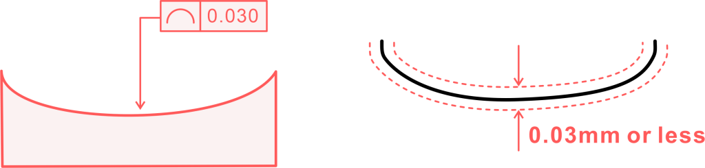
How you flag the Profile of a Line on a drawing all happens inside the feature control frame, the rectangular box that holds every part of the requirements.
You open with the line profile symbol. This symbol, an arc or half-circle, always sits in the first compartment. The moment someone reads the drawing, that symbol says a line profile requirement is applied here.
Just to the right, in the second compartment, sits the tolerance value. This figure gives the full width of the tolerance zone. Say the value reads 0.5: the two parallel lines of the boundary must then stand 0.5 mm apart. Note that the number sets the whole band, not a radius or an offset from one side.
Next you might spot a circle with a U inside it beside the tolerance. That flags an unequal bilateral zone, where the band does not split evenly around the true profile. With no such modifier, the split is assumed equal on both sides.
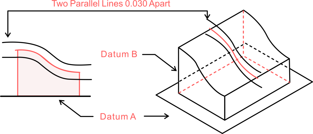
Then come the datums. If the frame names one or more (A, B, C, for example), the tolerance zone pins down not just the shape of the line but its orientation and location against those datums, which lock the zone in space.
With no datums called out, the callout treats the feature as pure shape: the slice may float and rotate freely, and only its shape has to fall inside the zone. A leader arrow runs from the frame to the surface being checked. One more consideration: the drawing may carry dashed lines marking the exact cross-section where the reading is taken.
How to Measure GD&T Profile of a Line
So how does a shop check parts against this spec? You have to read the shape variation the right way, and that usually calls for smarter kit, because you are matching the measured surface against a flawless ideal.
1. Coordinated Measuring Machine (CMM)
The go-to for accuracy is the CMM. Its probe touches many points along the exact cross-section you care about. The machine carries the basic dimensions from your CAD model, so it knows the true profile.
It registers the x, y, and z coordinate of every touch, then weighs each measurement against the nominal data. The software decides whether the measured points land inside the tolerance zone. Because a CMM gathers a dense measurement set with high precision, it shines on trickier geometry and confirms the shape. It copes with datum and non-datum callouts alike, provided you take enough measurements across a given cross-section to map the whole line element.
2. Profile Projector
A profile projector, or optical comparator, throws a magnified shadow of the slice onto a screen, a bit like the overhead projectors of old classrooms.
You lay a clear overlay, a template, on the screen. The template carries the true profile plus the upper and lower edge of the tolerance zone. Then you nudge the part’s shadow into line with it.
By eye, you compare the shadow’s edge against the two boundary curves of the template and see whether it stays between them. It is quick and handy for smaller parts, though for tight tolerances and busy curves it trails a CMM on reliability.
3. Laser Scanner
A 3D laser scanner is the fast modern way. It sweeps a huge measurement set off the surface in moments, building a dense point cloud of the real geometry of the part.
That cloud drops into software that compares it against the CAD model and its ideal shape. The software reads the slice you named and grades the measured shape against the tolerance zone. It is quick, it captures enormous data, and that pairing suits parts with knotty shapes. It gives a thorough read of surface tolerance by weighing a vast measurement count and confirming the measurement of the shape holds.
Profile of a Line (Line Profile) vs Other GD&T Callouts
It is easy to muddle the Profile of a Line with its GD&T neighbors. They can look alike on paper, yet they behave differently. Each has its own definition, so telling them apart is important, both for picking the right control and for inspection.
Profile of a Line vs Surface Profile
This is the classic mix-up, and the split comes down to dimensionality. The Profile of a Line is 2D, aimed at one line element on a single cross-section. One slice.
The surface profile is 3D. It governs the whole surface at once. Instead of two lines, its tolerance zone is built from two parallel surfaces, and every point on the entire surface, whatever its size, has to sit inside that 3D band. So one reads slices, the other reads everything together. Reach for the line version when the slice shape is the critical feature, and the surface profile when the whole 3D shape counts.
Profile of a Line vs Straightness
Straightness is a simpler form control. It asks only how straight a line element is, setting a tolerance zone bounded by two perfectly parallel straight lines. The line under scrutiny need not line up with anything else; it just has to be straight in itself.
The line profile carries far more reach. It can police a straight line, sure, but also arcs, splines, and other complex curves, its tolerance zone hugging the ideal shape whatever that shape is. Straightness cares about one thing. The Profile of a Line cares about matching a specific, defined shape. If all you need is a straight line, straightness does the job; if the line has to trace a set curved path, you want the line profile.
Profile of a Line vs Circularity
Circularity, or roundness, is a form control for features of revolution such as cylinders and cones, for example. It makes sure any slice of the feature is a true circle, with a tolerance zone of two concentric circles that every measured point on the rim must fall between.
A line profile can be applied to circular features too. With a perfect circle as the true profile, the Profile of a Line builds a zone of two concentric circles, matching circularity exactly. There they behave the same. The difference: the line profile also handles non-circular shapes that circularity cannot. Roundness governs roundness; the Profile of a Line governs any line shape you can pin with basic dimensions.
Where to Use Profile of a Line
So where does this control earn its keep? Plenty of places, because it is the best pick when you want to pin a feature’s shape at a given cross-section.
You see it on parts whose shape shifts along their length, like an aircraft wing or the curved surface of a car body panel. The slice shape drives performance, yet it changes from spot to spot, so you can drop the same callout at several stations and manage the contour of each slice. That is one answer to the question of how you tame a curved surface that never repeats.
It is a fine pick for policing the edge of a part, above all when that edge is a complex curve. Picture the edge of a cam lobe or the flank of a gear tooth, for example. If that line loses its exact shape, the part stops doing its job. That raises a second question: what happens at a mating face where two parts meet?
The line profile holds that shape. It also suits parts that seal against one another, where the slice shape of the sealing face makes or breaks the seal. And by design, it gives that shape check first, before the mating fit is set.
In addition, the Profile of a Line is a cleaner way to manage shape than a raw size tolerance, and once datums enter, when orientation and location matter, it hands you a firm, well-defined answer. The added complexity of a contoured part is exactly the kind of question the control was built to settle, which is why the requirements on such parts lean on it so often.
In the end, when the 2D story of a line element outweighs the size tolerance and the bulk of the 3D surface, the Profile of a Line is the callout to reach for.
Conclusion
By now the Profile of a Line reads as far more than a stray mark on a drawing.
It is a precise control for pinning down the shape of a line element. We saw its tolerance zone built from two parallel curves, and the rule that the measured shape has to match the true profile. We covered how to write it with the right symbol and callout, and the high-tech ways to measure how faithfully the shape came out. We sorted the common confusion with the surface profile, with straightness, and with circularity, so the definition of each control stays clear.
One consideration stands out: the Profile of a Line shines on parts with tangled geometry, used to ensure they behave exactly as drawn.
