

 EU
EUSlots, keyways, and opposing parallel surfaces on precision parts must sit perfectly centred. If they drift to one side, stress builds up unevenly and parts fail early.
GD&T Symmetry is the geometric tolerance that prevents this. It controls exactly where the midpoint of a feature sits relative to a datum plane.
This guide covers the Symmetry symbol and feature control frame, how the symmetry tolerance zone works, inspection methods including CMM, its status in ASME and ISO standards, and how it compares with Concentricity and True Position.
What Is GD&T Symmetry?
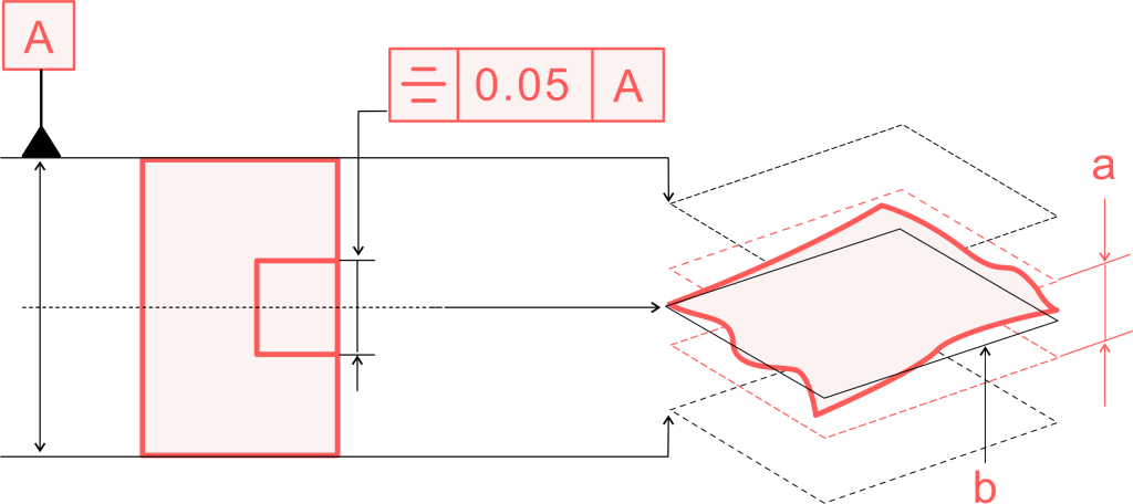
GD&T Symmetry is a 3D geometric tolerance that makes sure the median points of a feature are perfectly centred around a datum centre plane or datum axis. This symmetry control is used on slots, grooves, and parallel surfaces that must stay balanced and properly located.
Symmetry is a derived feature. We do not measure the feature surfaces directly. Instead, we find the midpoint between two corresponding points on opposite surfaces. The symmetry tolerance says all of these median points must fall within a narrow zone centred on the datum.
This is different from a simple dimensional check. A dimension tells you the size of a slot. The symmetry callout tells you where the centre of that slot must be relative to the datum reference frame.
Symmetry Symbol

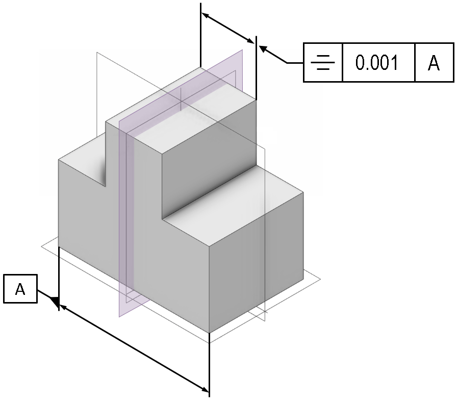
The GD&T Symmetry symbol looks like three short, equal-length horizontal lines stacked on top of each other. You won’t see it by itself. It always appears inside a feature control frame (FCF) on the engineering drawing.
The FCF is a rectangle divided into three compartments. The first contains the Symmetry symbol. The second contains the symmetry tolerance value (for example, 0.03 mm), which defines the total width of the tolerance zone. The third is the datum reference letter (for example, A), which tells you which datum plane the feature must be centred about.
The symmetry callout is always applied RFS (Regardless of Feature Size). This means the symmetry tolerance applies at whatever actual size the feature is produced. There are no bonus tolerances, and material condition modifiers like MMC or LMC cannot be used with this symmetry control.
Symmetry Tolerance Zone
The area where all the median points must fall is called the symmetry tolerance zone. It consists of two parallel planes equally spaced on either side of the datum centre plane. These virtual tolerance zone planes define the boundary for every median point on the controlled feature.
If the feature control frame specifies a symmetry tolerance of 0.03 mm, each plane sits 0.015 mm from the datum center plane. The total zone width is 0.03 mm, perfectly centred on the datum plane. The tolerance value is always the total width. A callout of 0.03 mm means 0.015 mm on each side, not 0.03 mm on each side.
The center plane shown on the drawing is the theoretical center plane of the datum. The tolerance zone is built symmetrically around it. All of the median points must fall within this tolerance zone to pass inspection. If any median point moves outside of these two parallel planes, the part does not meet the symmetry requirement.
Symmetry Tolerance Example
Consider a steel shaft with a 40 mm outer diameter and a keyway slot (10 mm wide, 4 mm deep) that must mate with a drive key. The symmetry requirement specifies centring on the shaft’s vertical centre plane (Datum A) to within 0.05 mm. The feature control frame reads: Symmetry | 0.05 | A.
The symmetry tolerance zone consists of two parallel planes spaced 0.025 mm on each side of Datum A’s centre plane, for a total zone width of 0.05 mm. During CMM inspection, the derived median points from opposite walls of the keyway must all fall within this zone. Each measurement point is compared against the theoretical center datum.
If the keyway drifts to one side, the drive key binds against one wall and concentrates stress there, increasing fatigue cracking risk. A symmetrical keyway distributes torque evenly across both walls. That is why the symmetry tolerance is specified here rather than a simple dimensional check.
How to Measure Symmetry
Symmetry is one of the hardest GD&T callouts to verify because we are measuring derived median points, not actual surfaces.
Using a Calliper or a Micrometer
A calliper, micrometre, or even an analog caliper can measure the width of a slot or the distance between two parallel surfaces. However, these instruments measure size only. They cannot establish the reference plane or calculate whether a feature is positioned to exactly center on the datum plane.
A skilled inspector might manually calculate the midpoint from each side, but this captures only a handful of measurement points and introduces measurement error. The measured values require manual recording and do not provide enough measurement data to properly measure this tolerance for any critical application.
Using a Coordinate Measuring Machine (CMM)
A coordinate measuring machine is the most accurate way to check symmetry. Unlike position control or form tolerances, the symmetry requirement depends on derived median points, which needs a measuring machine with dedicated software.
Step 1: The CMM probes the datum feature and calculates a theoretical midpoint datum plane, or virtual plane, as the reference plane.
Step 2: The CMM touches dozens to hundreds of points on each opposing surface of the controlled feature. These repeated measurements across both symmetrical surfaces ensure enough data for the median plane calculation.
Step 3: The software pairs corresponding points on the opposite surfaces and calculates each midpoint. These form the derived median plane, approximating the exact median plane of the feature.
Step 4: The software measures each point’s distance from the central datum plane. If every derived median point falls within the symmetry tolerance zone, the part has been accurately measured and passes.
One challenge: different CMM software packages use slightly different algorithms for pairing points. This inconsistency was one reason ASME removed Symmetry from its 2018 standard.
Why Should You Use Symmetry?
Despite its limited functional scope, there is no substitute when the symmetry requirement is genuinely about mass balance and form distribution.
High-Speed Rotating Components
Out-of-balance turbines, engines, and rotating shafts cause vibrations, noise, accelerated wear, or catastrophic failure. The symmetry tolerance ensures the feature axis aligns with the rotation axis. Any off-centre slot disrupts static and dynamic balance.
Heavy Load-Bearing Parts
Symmetrical features spread force evenly across each reference element, lowering localised stress concentration risk. Bearings, gear teeth, and support brackets all require the target element to be centred on the datum plane for proper load distribution.
Cyclic and Fatigue Loading
Asymmetrical parts take on more stress than they should during cyclic loading. Uneven features accelerate fatigue failure when machinery vibrates or moves back and forth.
Preventing Crack Initiation
Symmetry controls keep cracks from starting by ensuring even stress distribution across the feature surfaces. Features balanced around a central plane spread stresses across the entire structure, greatly increasing component service life.
The symmetry tolerance is not often specified unless absolutely necessary. CMM inspection costs and measurement challenges mean most designers prefer alternatives when possible.
Symmetry vs Other GD&T Controls
In GD&T, Symmetry is a location control used relative to a datum plane. How does it compare with other location controls?
Symmetry vs Concentricity
Symmetry and Concentricity are the same concept applied to different shapes. ASME Y14.5 (2009 and earlier) states this explicitly. The symmetry control constrains features with two opposing parallel surfaces. The surface form of these opposing reference features must be balanced about the median plane for the part to meet the symmetry requirement.
Concentricity controls cylindrical features using a cylindrical tolerance zone centred on a datum axis. It derives a central axis rather than a median plane. Both were removed from ASME Y14.5-2018. Both remain valid under ISO 1101:2017.
Symmetry vs True Position
True Position is the primary replacement for Symmetry. It is more common, more flexible, and easier to inspect. True Position can use MMC and LMC modifiers for bonus tolerances, allow datum feature shift, and support a projected tolerance zone. Symmetry cannot do any of these.
Symmetry is always applied RFS. Size is not automatically controlled by the symmetry tolerance the way it is when position tolerance includes an MMC modifier. Under ASME Y14.5-2018, Position at RFS is the recommended replacement. The measurement does not rely on derived median points, so results from repeated measurements are more consistent.
Conclusion
GD&T Symmetry is a specific and powerful geometric tolerance for ensuring a feature is perfectly balanced about a datum plane. It uses a Symmetry symbol in a feature control frame (FCF) to define a symmetry tolerance zone of two parallel planes. All the median points must lie inside that zone.
This symmetry control was removed from ASME Y14.5-2018 due to measurement inconsistency and misapplication. The symmetry tolerance remains valid under ISO 1101:2017, and thousands of legacy drawings still carry the symmetry callout. Position tolerance at RFS is the recommended replacement. The entire surface of the controlled feature no longer needs median point evaluation when Position is used instead.
For any part where balance, load distribution, or fatigue resistance depends on centred features, understanding Symmetry and its alternatives remains essential.
