

 EU
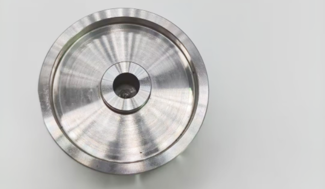
A blind hole is a machined hole that stops at a specific depth without penetrating the opposite side of a workpiece. Unlike through holes, blind holes create internal cavities while keeping the outer surface intact.
Blind holes are widely used for fasteners, alignment features, fluid channels, and component assembly. Achieving accurate depth, tight dimensional accuracy, and clean finishes requires proper tool selection and machining control.
This article explains blind hole symbols, machining methods, common applications, and key design considerations for engineers and machinists working with CNC machined parts.
What Is a Blind Hole?

A blind hole is an internal cavity that opens from one side of a workpiece while leaving material at the bottom. The hole depth is controlled during machining to create a defined stopping point.
The bottom shape depends on the cutting tool used. A standard twist drill typically creates a conical bottom, while flat-bottom designs require additional machining with an end mill or flat-bottom drill.
In engineering drawings, blind holes are defined by their diameter and depth dimensions.
Blind Hole Symbol
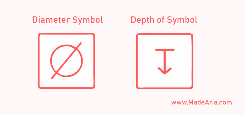
Blind holes are shown on engineering drawings with a diameter dimension and a depth indication. The depth symbol, ↧, marks the point where the hole stops, as in this callout:
- ⌀10 ↧15
This indicates a 10 mm diameter blind hole that is 15 mm deep at full diameter. The cone-shaped tip left by the drill is not included in the depth.
A threaded blind hole needs two depths on the drawing: the full thread depth and the drill depth for the tap. A typical callout looks like this:
- ⌀6.8 ↧16M8×1.25-6H ↧12 MIN FULL THD
This means an M8 coarse thread with a 6H tolerance class and at least 12 mm of full thread, cut into a 6.8 mm pilot hole drilled 16 mm deep. The pilot hole is deeper than the thread because a tap cannot cut full threads all the way to the bottom, and the extra depth also leaves room for chips.
Blind Hole vs Through Hole
A blind hole stops at a set depth and leaves material below it, while a through hole passes through the whole part and opens on both sides. Through holes are usually faster and cheaper to machine because chips and coolant exit from the far end.
Blind holes are the better choice when the opposite surface must stay closed. For a full comparison of drawing callouts, tapping, cost, and selection, see our guide on blind hole vs through hole.
How to Drill a Blind Hole?
Blind hole machining uses drilling, milling, boring, or reaming to reach a controlled depth on CNC equipment. Because chips must leave through the same opening the tool enters, the right method depends on hole depth, diameter, bottom shape, and whether the hole needs threads or a tight tolerance.
Twist Drilling
Twist drilling is the most common and cost-effective method for standard blind holes. A spot drill is usually run first so the twist drill starts in the right position without wandering.
End Milling
End milling is used when a blind hole needs a flat bottom, tighter dimensional control, or a better surface finish. It is also the standard method for precision pockets, shallow cavities, and holes larger than a stock drill size.
Peck Drilling
Peck drilling is used for deeper blind holes where chip removal becomes difficult. The tool advances in short steps and retracts periodically to clear chips and let coolant reach the cutting area. This reduces chip buildup, heat, and tool wear in deep holes.
Tapping Blind Holes
Tapping is the riskiest step in making a blind hole, because chips have nowhere to go and the tap can hit the bottom. Spiral flute taps pull chips up and out of the hole, while form taps press the thread into the material and produce no chips, which suits aluminum and other ductile metals. A bottoming tap can bring full threads closer to the bottom when drill depth is limited.
For hard materials or high-value parts, thread milling is the safer option. The cutter is smaller than the hole, so a broken tool is easy to remove, and thread depth can be adjusted in the program instead of by changing tools.
Advantages and Disadvantages of Blind Holes
Blind holes provide functional advantages in part design, but they also introduce additional machining requirements compared with through holes.
Pros
- Maintains Surface Integrity: Blind holes keep the opposite side of the component intact, which helps preserve external surfaces and supports sealed designs.
- Provides Internal Mounting Features: Threaded blind holes allow fasteners and locating features to be installed without creating openings through the entire part.
- Supports Sealing and Protection: The closed bottom helps prevent fluid leakage and protects internal areas from external contaminants in applications such as housings and manifolds.
Cons
- More Difficult Chip Removal: Chips must exit through the same opening where the tool enters, increasing the risk of chip buildup and heat accumulation.
- Higher Machining Complexity: Blind holes require accurate depth control, proper tooling, and careful process planning, especially for deep holes or internal threads.
- More Challenging Inspection: Measuring hole depth, bottom geometry, and internal features may require specialized inspection methods.
Engineering Applications
Blind holes are commonly used in parts that require internal mounting, sealing, or precise positioning without creating a through opening.
- Hydraulic and Pneumatic Parts: Blind holes are used for threaded ports, mounting points, and internal passages. The closed bottom helps maintain sealing performance and prevent fluid leakage.
- Automotive Industry: Engine and transmission parts use blind holes for fasteners, sensor mounts, and assembly features where a sealed surface or controlled depth is required.
- Aerospace Industry: Blind holes are used for fasteners and locating pins in precision assemblies. They help maintain surface integrity while providing accurate alignment between components.
- Electronic Housings and Mechanical Enclosures: Blind threaded holes allow internal components and brackets to be mounted without affecting the exterior appearance of the product.
Design Considerations of Blind Holes
Designing blind holes requires balancing functional requirements with machining limitations. Engineers should consider material properties, hole depth, placement, and tolerances to ensure manufacturability.
Material Properties
The workpiece material affects cutting forces, chip shape, and tool wear when machining blind holes. Aluminum and copper cut quickly but tend to stick to the tool, while stainless steel and titanium work-harden and wear tools faster. These materials often need sharper tools, adjusted feeds, or coolant through the tool to keep blind holes clean and accurate.
Depth and Diameter Control
The deeper a blind hole is relative to its diameter, the harder it is to clear chips and hold position. Standard drilling works best up to about 3 to 5 times the diameter, and deeper holes need peck cycles, coolant through the tool, or gun drilling. Avoid making a hole deeper than its function needs. For threaded blind holes, drill several thread pitches deeper than the full thread depth, and leave enough wall below the drill point so it cannot break through the far side.
Placement and Orientation
Keep blind holes far enough from edges and other features to protect wall strength and give the tool room to work. Where possible, place holes on surfaces square to the tool axis. On curved or angled faces the drill tends to walk, so a spot face or milled flat at the entry gives it a stable start.
Tolerances and Surface Finish
Tolerance and surface finish requirements should match the function of the blind hole, especially where a pin needs a precise fit. Standard drilling may be suitable for general applications, while tighter requirements may require secondary operations such as reaming or boring.
Final Takeaway
Blind holes provide controlled-depth features for fastening, alignment, mounting, and sealing without opening the opposite surface. The machining method depends on hole depth, diameter, bottom shape, material, tolerance, and whether the hole is threaded.
Good blind hole design starts with chip evacuation, tool access, depth control, and thread engagement. Aria’s engineering team reviews hole depths, thread callouts, and tool access as part of every CNC machining quote, so design issues are caught before production starts.
