

 EU
EUAchieving exact hole dimensions and exceptional surface finishes often requires more than standard drilling. The boring machining process is a precision secondary operation used to refine, enlarge, and align pre-existing holes in metal and plastic components.
This article covers how the boring process works, key machine types, common applications, and practical optimisation strategies, with direct comparisons to drilling, turning, and reaming.
What Is Boring Machining?
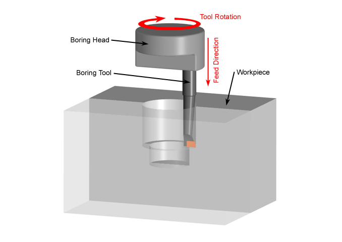
Boring machining is a subtractive precision process used to enlarge, straighten, and refine pre-existing holes in metal and plastic workpieces. It uses a specialised single-point cutting tool or boring head to correct, expand, and finish a hole that has already been drilled, cast, or forged. Unlike drilling, which creates a hole from solid material, boring is an internal diameter (ID) finishing process.
Boring is used when tight tolerances and smooth surface finishes are required. The boring machining process serves three core functions:
- Enlarging to exact dimensions: Expands pre-existing holes to target diameters with tight tolerances, often down to ±0.0005 inches, with high-quality surface finishes.
- Correcting concentricity and alignment: Fixes location errors so the hole centreline is concentric with external diameters or neighbouring features.
- Straightening bore axis: Eliminates hole wander from drilling, casting, or forging, producing a straight, true bore.
How Does Boring Machining Work?
The boring machining process uses a single-point cutting insert mounted on a boring bar to remove material from the inner diameter of a workpiece.
#1. On a lathe:
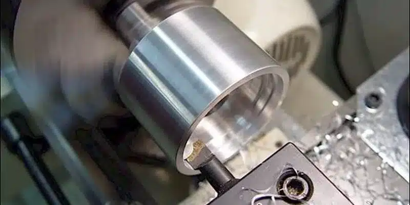
The workpiece rotates while the stationary boring bar feeds into the hole.
#2. On a milling machine or boring mill:
The workpiece remains stationary while the spindle rotates the boring tool into the bore.
#3. Prepare and mount the tool:
The machinist selects a boring bar based on the required hole size and hole depth, limits tool overhang for stability, and ensures proper alignment with the bore during setup.
#4. Set cutting parameters:
Spindle speed, feed rate, and depth of cut are configured based on the workpiece material and required tolerance.
#5. Rough boring:
The first pass removes the bulk of the material, correcting runout or casting defects.
#6. Finish boring:
A light cut at lower feed rates delivers the final dimensions and surface quality.
#7. Verify hole geometry:
The boring tool corrects out-of-roundness, taper, and axial drift, producing a straight, concentric bore. For large components with multiple bores on a common axis, line boring aligns all bores in a single setup.
When boring blind holes, allow adequate chip clearance at the bottom and set precise depth stop points to prevent the cutting tool from contacting the workpiece base.
What Are the Types of Boring Machines?
Boring machines are categorised by spindle orientation and machining capability. Below are the most common types.
Horizontal boring machines
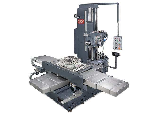
A horizontal boring machine has a horizontally oriented spindle. The boring bar moves horizontally, which suits large parts and deep holes where tool deflection must be minimised. Besides boring, these machines can also perform drilling, milling, and reaming.
Horizontal boring machines are divided into two main configurations:
- Table type: The most common variant. An adjustable table positions the workpiece for multi-sided machining. Table type machines are versatile and widely used in automotive, aerospace, and general manufacturing.
- Floor type: Built without a machine table. The workpiece is secured on T-slotted floor plates. Floor type machines handle massive components such as ship hulls and heavy construction frames. They are often equipped for line boring to maintain alignment across multiple inline bores.
Vertical Boring Machines
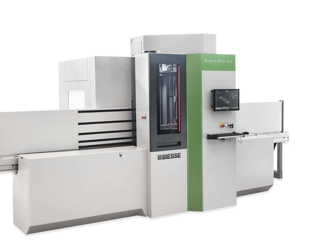
A vertical boring machine has a vertically aligned spindle. The workpiece is clamped horizontally onto a rotating turntable. This layout provides stable support for heavy, large-diameter components that are difficult to clamp on a horizontal spindle.
In operation, the tool moves along the vertical boring axis while the workpiece remains supported on the table. The vertical orientation reduces vibration, tool deflection, and chatter on large-diameter bores.
Precision Boring Machines
Precision boring machines are designed for tight tolerances and high-quality surface finishes. They feature rigid high-speed spindles, precise feed rate controls, and digital readout or CNC integration. Available in both horizontal and vertical layouts, precision boring machines are common in the aerospace, automotive, and medical device sectors.
Micro boring is a specialised subset of precision boring used for very small internal diameters (under 1 mm) in electronics and medical implant components. The precision barrel boring machine, an early form of precision boring equipment, played a key role in the development of modern high-accuracy boring technology.
Applications of Boring Machining
The boring machining process is used across a wide range of industries where precise internal diameters, tight tolerances, and high-quality surface finishes are required.
- Automotive: Sizing engine cylinders, machining main bearing bores, camshaft housings, and transmission cases. CNC boring is standard for high-volume engine block production.
- Aerospace: Creating exact tolerances for turbine casings, landing gear parts, and actuator fluid control ports.
- Oil and Gas: Finishing thick-walled pipe interiors, high-load valve bodies, and industrial pump housings.
- Heavy Equipment: Line boring aligned holes in large construction frames, cranes, and structural gearboxes.
- Hydraulics and Fluid Power: Creating smooth, leak-free interior walls for hydraulic and pneumatic cylinders.
- Medical Devices: Precision boring of surgical instrument housings and implant components where tight tolerances and surface finish are critical.
- General Manufacturing: Processing decorative holes for jewellery, furniture pieces, and consumer products where appearance matters.
Advantages of Boring Machining
High precision and accuracy:
The cutting tool is aligned with the centreline of the existing hole. By separating roughing and finishing passes, the boring process corrects hole taper, out-of-roundness, and axial drift, achieving tolerances as tight as ±0.0005 inches (±0.012 mm).
Exceptional surface quality:
Fine boring produces surface roughness as low as Ra 0.4 to 0.8 µm. In many cases this eliminates the need for secondary finishing such as grinding or honing.
Versatility:
The boring process can be performed on lathes, milling machines, and dedicated boring machines in both horizontal and vertical configurations. Adjustable boring heads and modular cutting tool inserts support a range of hole diameters without custom-sized tooling.
Cost efficiency on high-tolerance parts:
Boring is slower than drilling, but it prevents scrapped parts by correcting alignment and sizing in a single setup. This reduces rework on high-value components.
CNC compatibility:
CNC boring minimises human error and delivers consistent results across production runs. Automated feeds and digital tool wear compensation on the boring tool support high-volume, repeatable output.
Challenges in Boring Machining
Boring involves cutting inside a confined space, which creates challenges that external machining does not have. Below are the most common issues and how to address them.
Tool deflection and chatter
The boring bar must extend into the hole, and a long bar relative to its diameter can bend and vibrate. This causes chatter marks, poor surface finish, and dimensional errors. Tool deflection is the most critical challenge in the boring machining process because it directly affects bore accuracy.
Keep the boring bar as short as possible. For deep holes where the length-to-diameter ratio exceeds 4:1, use solid carbide or anti-vibration damped boring bars. Reduce the depth of cut and use a cutting tool insert with a smaller nose radius to lower cutting forces.
Chip evacuation
Unlike external turning, boring traps chips inside the hole. Re-cutting trapped chips damages the surface finish and can chip the cutting tool.
Use high-pressure internal coolant delivered through the boring bar to flush chips outward. Select chip breaker inserts designed for internal boring to produce short, manageable chips.
Tool wear and heat build-up
Cutting inside a confined space generates heat that accelerates cutting tool wear, especially on stainless steel and high-temperature alloys. Worn boring tools cause taper errors and out-of-spec diameters.
Optimise cutting speed and feed rate based on material hardness. Use heat-resistant coated carbide inserts and maintain consistent coolant flow throughout the boring process.
Bore taper and misalignment
A long boring bar can deflect at the tip, causing the hole to narrow toward the bottom and creating an unintended taper. Machine misalignment or bed wear can also affect concentricity. Tool deflection at the boring bar tip is the primary cause of bore taper in deep hole boring.
Use multiple light finishing passes to minimise tool push-off. Perform regular machine calibration and use CNC boring tool wear compensation to correct taper errors automatically.
Boring Machining Vs. Other Machining Processes
Understanding how boring compares to other hole-making processes helps machinists choose the right technique for a specific project.
Boring vs Drilling
Drilling uses a drill bit to create new holes in solid material. The boring process is performed on existing holes to enlarge them and improve surface finish and accuracy.
Drilling is typically used for smaller holes, while boring offers more control on larger diameters. The precision difference is significant: drilling has a typical accuracy of 0.02 inches, while boring can achieve about 0.0005 inches. For high-volume production, CNC boring combined with CNC drilling streamlines the complete hole-making process.
Boring vs Turning
Both boring and turning are subtractive processes commonly performed on a lathe. The key difference is that boring removes material from the inside of a hole using a boring bar and cutting tool, while turning removes material from the external surface of the workpiece.
The two processes often work together on the same part. A CNC lathe can perform both turning and CNC boring operations in a single setup, reducing handling time and improving concentricity between internal and external features.
Boring vs Reaming
Boring and reaming are both used to refine existing holes. The difference is in the amount of material removed and the level of accuracy achieved.
Reaming removes a small amount of material to improve surface finish and bring the hole to its final size. Boring can remove more material, creating a significantly larger diameter. The boring process achieves higher accuracy at about 0.0005 inches compared to 0.001 inches for reaming. However, reaming is faster when only minor sizing adjustments are needed.
Conclusion
Boring machining is a critical process for producing precise internal diameters across automotive, aerospace, oil and gas, heavy equipment, and medical device applications. The choice between manual and CNC boring depends on production volume, required tight tolerances, and part complexity.
For CNC machined components that require accurate bores, specifying the right boring process, boring tool, and cutting parameters at the design stage avoids rework and ensures consistent quality in production.
Need precision bored holes or CNC machined components? Aria Manufacturing offers CNC boring and precision machining services for custom metal and plastic parts. Contact us for a quote.
