

 EU
Slip fits and press fits both control how a shaft or pin seats in its mating bore. A slip fit lets the parts slide together by hand and come apart just as easily. A press fit forces them together, so the joint holds load without keys or fasteners.
Pick the wrong one, and a joint that should hold will slip, or a part that should come out will not. This guide covers how each fit works, how to calculate it, and how to choose the right one for your project.
What Is a Slip Fit?
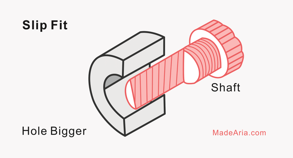
A slip fit is a clearance fit where the shaft or pin is made slightly smaller than the hole. The gap lets the parts slide together by hand, with no press, hammer, or heat.
The clearance is small, usually about 0.01 to 0.05 mm for shafts between 10 and 50 mm. That is enough for the parts to rotate, slide, or come apart for service, and tight enough to keep them aligned. On drawings, slip fits are usually called out with an ISO fit designation such as H7/h6, H7/g6, or H8/f7.
A slip fit does not hold parts in place. To carry torque or axial load, it needs a key, set screw, or retaining ring. For clearance classes and full tolerance tables, see our guide to slip fit tolerances.
Slip Fit Examples
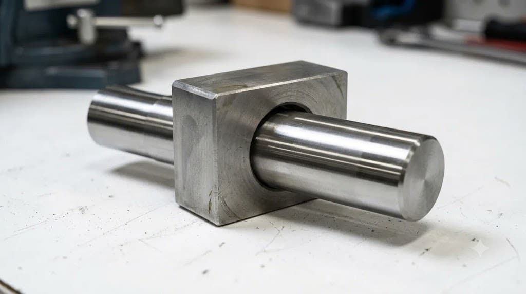
A ground steel shaft passing through a reamed bore in a square guide block is a typical slip fit. The shaft slides through by hand without wobbling, so the block stays centered on the shaft and can still be moved along it or taken off for service. The same arrangement shows up in fixture guide rails, idler shafts, and linkage pivots, where a fit such as H7/g6 keeps the running play to a few hundredths of a millimeter.
How to Calculate a Slip Fit
A slip fit is checked by its clearance range, which comes from the size limits of the hole and the shaft.
- Minimum clearance = smallest hole − largest shaft
- Maximum clearance = largest hole − smallest shaft
The minimum clearance must be zero or positive. If it goes negative, the parts can interfere. For a guaranteed positive clearance, choose H7/g6 over H7/h6.
Take a Ø25 mm H7/g6 fit. Per the ISO 286 fit tables, the hole measures 25.000 to 25.021 mm and the shaft measures 24.980 to 24.993 mm. The minimum clearance is 25.000 − 24.993 = 0.007 mm. The maximum clearance is 25.021 − 24.980 = 0.041 mm. Any pair made within the specified tolerances will assemble with a gap in that range.
In mixed material assemblies, check the clearance at operating temperature too. Aluminum expands roughly twice as much as steel, so an aluminum shaft in a steel bore can close a small gap completely.
What Is a Press Fit?
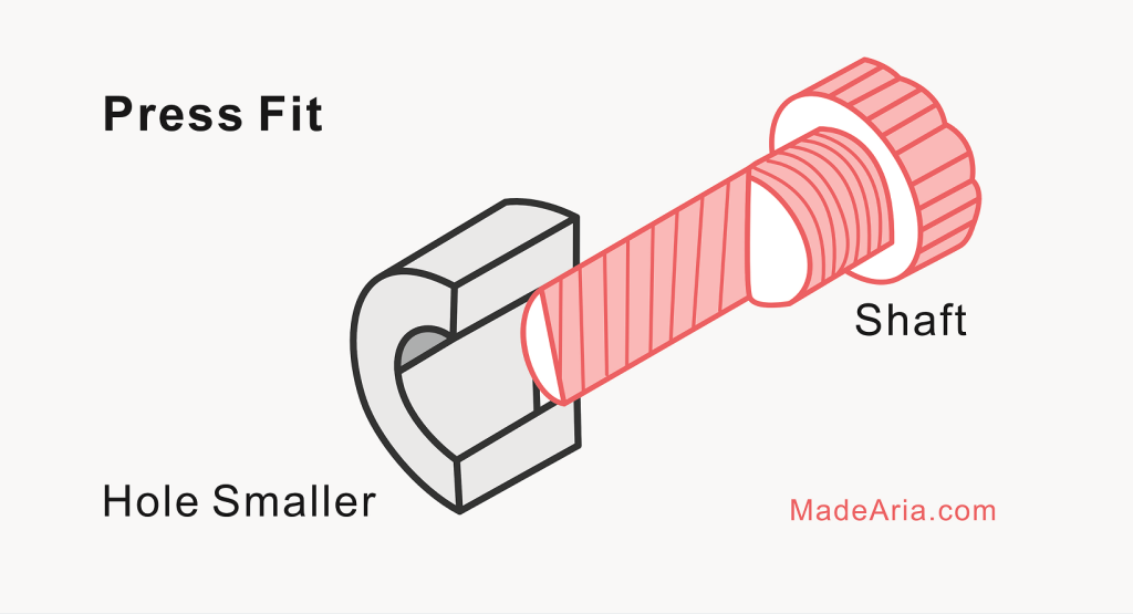
A press fit, also called an interference fit, is a joint where the shaft or pin is slightly larger than the hole, so force is needed to put the parts together. Assembly uses a press, or heat on the hub, or cold on the shaft.
The interference is small, usually about 0.01 to 0.05 mm for shafts between 10 and 50 mm. Both parts deform elastically, and the contact pressure creates friction that locks the joint. It holds torque, axial load, and vibration without keys, screws, or glue. On drawings, press fits are usually called out with ISO codes such as H7/p6 or H7/s6.
The trade-off is removal. Pulling the parts apart often damages the surfaces, and too much interference can crack a thin hub.
Press Fit Examples
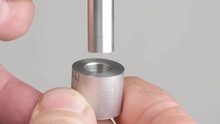
A steel pin pressed into an aluminum sleeve is a common press fit. The pin is slightly larger than the bore, so it has to be driven in with an arbor press, and once seated it cannot spin or work loose. The same method holds dowel pins in fixture plates, shafts in aluminum rollers and pulleys, and steel inserts in light alloy housings. Because aluminum is softer than steel and expands more with heat, these joints usually use a lighter interference than a steel hub would.
How to Calculate a Press Fit
A press fit is checked by its interference range, which comes from the size limits of the shaft and the hole.
- Minimum interference = smallest shaft − largest hole
- Maximum interference = largest shaft − smallest hole
Both values must be positive. If the minimum goes to zero or below, some pairs will not grip.
Take a Ø25 mm H7/p6 fit. Per ISO 286, the hole measures 25.000 to 25.021 mm and the shaft measures 25.022 to 25.035 mm. The minimum interference is 25.022 − 25.021 = 0.001 mm. The maximum interference is 25.035 − 25.000 = 0.035 mm.
Interference alone does not tell you how strong the joint is. For a solid steel shaft in a steel hub, the contact pressure, axial force, and torque capacity can be estimated as:
- p = (E × δ / 2d) × (1 − d² / D²)
- F = μ × p × π × d × L
- T = F × d / 2
E is Young’s modulus, δ is the diametral interference, d is the shaft diameter, D is the hub outer diameter, L is the engagement length, and μ is the friction coefficient. F estimates both the force to press the parts together and the axial load the joint can hold. Actual press force also depends on chamfers, lubrication, and surface condition. Use the minimum interference to confirm the joint holds under load. Use the maximum interference to size the press and check that the hub will not crack.
Differences Between Slip Fit and Press Fit
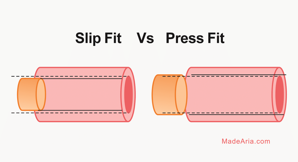
The main difference between a slip fit and a press fit is the gap between the mating parts. A slip fit never has interference, so the parts slide together. A press fit always has interference, so the parts grip each other. That one difference drives everything else.
| Slip Fit | Press Fit | |
| Fit type | Clearance | Interference |
| Ø25 mm example | H7/g6, 0.007 to 0.041 mm gap | H7/p6, 0.001 to 0.035 mm overlap |
| Relative motion | Parts can rotate or slide | Parts are locked together |
| Part deformation | None | Elastic deformation at the interface |
| Alignment | Small play, position can be adjusted | Fixed and concentric once assembled |
| Assembly | By hand | Press, or heat and cold |
| Disassembly | By hand, repeatable | Puller or press, may damage parts |
| Holding force | None on its own | Friction from contact pressure |
| Torque and axial load | Needs a key, pin, or retaining ring | Carried by the fit itself |
| Cost | Lower | Higher machining control and assembly equipment |
| Typical uses | Locating pins, guide bushings, floating bearing rings | Bearing inner rings, bushings, gear hubs |
Tolerance Range
Both fits often use the same IT grades, such as an H7 hole with a grade 6 shaft. The difference is the shaft designation, which sets where the shaft tolerance zone sits. For a slip fit, it sits below the hole. For a press fit, it sits above.
Press fits are less forgiving. A slip fit only has to avoid a negative gap. A press fit has to stay within both limits, because too little interference loses grip and too much can crack the hub. That extra control, plus the press or heating equipment, makes press fits more expensive to produce.
Assembly Methods
A slip fit goes together by hand, sometimes with a light coat of oil.
A press fit needs controlled force from an arbor or hydraulic press. A chamfer on the shaft guides entry, and oil reduces friction. For heavy interference, thermal assembly takes over. The hub is heated or the shaft is cooled so the parts slide together, then grip as temperatures equalize.
Disassembly
A slip fit comes apart the same way it went together and can be serviced many times.
A press fit needs a puller or press, and the surfaces often score on the way out. Each removal also reduces the interference, so a reused joint holds less than a new one.
Holding Force
A slip fit has no contact pressure, so it has no holding force of its own. Anything that must stay put needs a separate retention feature.
A press fit holds by friction. Holding force rises with interference, shaft diameter, engagement length, and hub wall thickness.
Load Capacity
A slip fit carries radial load through surface contact but cannot carry torque or axial load without help. Under vibration, the gap allows small movements that cause fretting and wear.
A press fit carries torque, axial load, and vibration together. Its limit is hub stress. Temperature also matters. An aluminum housing or hub on a steel shaft expands more when hot and can lose grip at operating temperature.
Applications
The two fits often work together. On a rotating shaft, standard practice is to press the bearing inner ring onto the shaft so it cannot creep. At the non-locating end, the outer ring slips into the housing so it can float as the shaft grows in length with heat. Dowel pins follow the same logic, pressed into one part and slipped into the other.
Slip fits are common in fixtures, tooling, and equipment that needs regular maintenance. Press fits are standard in automotive drivetrains, aerospace assemblies, and heavy machinery where joints must survive vibration. Use a slip fit where parts move, align, or come apart. Use a press fit where parts must stay fixed and carry load without extra hardware.
How to Choose the Right Fit for Your Project
Start with function. If the parts must move or come apart in service, use a slip fit. If the joint must carry torque or axial load without a key or fastener, use a press fit. If you need accurate location and a key will carry the torque, a transition fit sits between the two (see the overview of fit types below).
The four factors below then decide the exact fit class.
Nominal Diameter
ISO tolerances grow with nominal size. An H7 hole has an 18 µm tolerance band at 10 to 18 mm, but 35 µm at 80 to 120 mm. On small pins, a few microns of error is a large share of the interference, so press fits are harder to hold. On large shafts, press force rises quickly, and heating the hub often replaces a mechanical press.
Surface Finish
In a press fit, surface peaks flatten during assembly and reduce the effective interference. Many designers specify Ra 1.6 µm or finer on both mating surfaces for this reason. In a slip fit, rough surfaces can make a tight fit such as H7/h6 bind even when both parts measure in tolerance.
Material Combination
Different thermal expansion rates can close a slip fit or loosen a press fit at operating temperature. Aluminum needs more interference to reach the same contact pressure but yields sooner. Cast iron is weak in tension, so its hubs need lighter interference or thicker walls. Plastics creep and can lose grip over time, and stainless steel on stainless steel tends to gall without lubrication.
Cost and Equipment
A slip fit is the lower-cost option. Standard CNC machining, such as turning and reaming, can hold most slip fit diameter tolerances, and assembly needs no special tools.
A press fit costs more at every step. Shafts may need grinding, often after heat treatment. Bores may need finish boring or honing, and inspection is tighter. Assembly needs a press, and heavy fits add induction heaters or cryogenic cooling. If that cost is hard to justify, a slip fit with a key or pin can carry the load instead. Whichever fit you choose, the drawing should state the fit designation, surface finish on both mating surfaces, and how the bore and shaft will be inspected.
Overview of the Three Main Types of Engineering Fits
An engineering fit describes how tightly a shaft and hole go together. Every pairing falls into one of the three main types of fit in engineering.
Clearance Fit
The shaft is never larger than the hole, so the parts go together by hand. Clearance fits range from a loose fit with generous running clearance to close sliding fits used for location. A slip fit is the tighter end of this range, with common ISO fits such as H7/h6, H7/g6, and H8/f7. In the ANSI B4.1 inch system, also tabulated in Machinery’s Handbook, clearance fits are the RC and LC classes.
Transition Fit
Depending on actual part sizes, the assembly may have a small gap or a small overlap. For Ø25 mm H7/k6, it ranges from 0.015 mm interference to 0.019 mm clearance. Assembly takes a mallet or light press. Transition fits give accurate location but need a key or set screw to carry torque. Common ISO fits are H7/k6 and H7/n6, and the ANSI equivalents are the LT classes.
Interference Fit
The shaft is always larger than the hole, so the parts must be forced together. A press fit is the most common form, with ISO fits such as H7/p6 and H7/s6. Heavier versions such as H7/u6 are often called shrink fits, assembled by heating the hub or cooling the shaft. In the ANSI system, these are the LN and FN classes.
In short, clearance fits allow movement, transition fits give accurate location, and interference fits lock parts together.
Final Thoughts
For most designs, the choice comes down to one question: should the parts move, or should they stay put? A slip fit keeps an assembly easy to align and service. A press fit keeps it locked under load without extra hardware. Either way, the fit only works if the shaft and bore are machined to the specified tolerances.
If you are sourcing fit-critical parts, Aria Manufacturing can machine shafts, bores, and bushings to your ISO fit callouts and review the drawing before production.
