

 EU
A shaft and a bore can both meet their manufacturing tolerances and still fail to assemble. One binds. Another rattles. The dimensions are usually fine. The clearance between them was never controlled.
The right clearance depends on the fit class, part size, and application. Too little causes binding, and too much causes unwanted movement. This guide explains slip fit tolerance classes, how clearance is calculated, and how to apply them to CNC machining parts.
What Is a Slip Fit?
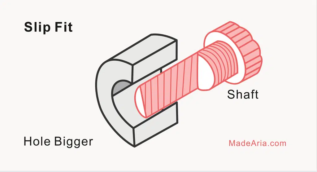
A slip fit is a clearance fit in which the shaft is machined a little smaller than its mating hole, so the two parts go together by hand and can slide or rotate without binding. No press, hammer, or heating is needed. For shafts in the 10 to 50 mm range, the gap is typically a few hundredths of a millimeter, small enough to keep parts aligned and large enough for free movement and easy disassembly.
Engineers specify slip fits with ISO 286 codes such as H7/g6, H7/h6, and H8/f7. Tighter versions are often called locational clearance fits. Because there is no interference, a slip fit cannot hold parts in place on its own. Joints that must transmit torque or resist axial force need a key, set screw, pin, or retaining ring.
How Does a Slip Fit Work?
A slip fit depends on three things:
- Clearance that never goes negative: The shaft is never larger than the hole, even when the largest allowed shaft meets the smallest allowed hole. At the tightest end, such as H7/h6, the two can meet at zero clearance, but they never interfere. This is what separates a slip fit from a transition fit, where some pairs can interfere.
- No assembly force: Parts go together and come apart by hand. They can be pulled and reinserted many times without damage, which suits parts that are serviced, adjusted, or swapped often.
- Defined by ISO fit codes: The fit is set on the drawing with a code such as H7/g6. The capital letter sets the hole tolerance zone, the lowercase letter sets the shaft zone, and the number sets the tolerance grade. Together they fix the minimum and maximum clearance.
What Is Slip Fit Clearance?
Slip fit clearance is the gap between the mating surfaces of a hole and a shaft. It is calculated by subtracting the shaft diameter from the hole diameter:
Clearance = Hole Diameter − Shaft Diameter
For example, a 20.02 mm hole and a 20.00 mm shaft have 0.02 mm of diametral clearance. The gap on each side, called radial clearance, is half that, or 0.01 mm. Fit tables always list diametral clearance, so check which one a drawing or supplier means.
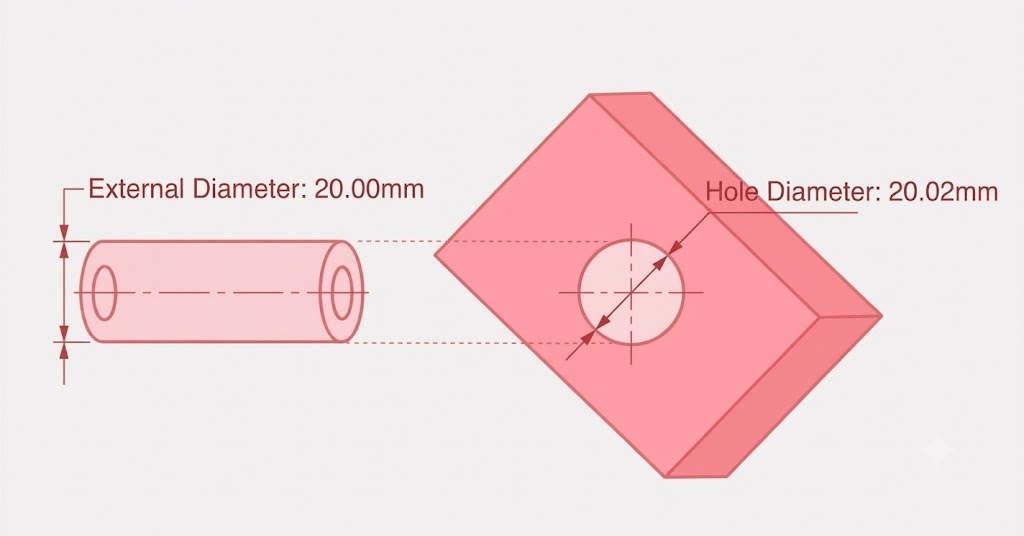
The amount of clearance determines how the fit behaves. A smaller clearance provides tighter alignment with less movement. More clearance gives easier assembly and more movement.
How to Calculate Slip Fit Clearance
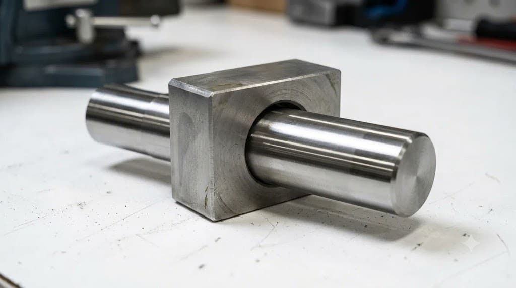
Real parts are never made to a single exact size. Each diameter has a tolerance band, so a fit produces a clearance range rather than one value:
- Minimum clearance = smallest hole − largest shaft
- Maximum clearance = largest hole − smallest shaft
For a slip fit, the minimum must be zero or positive.
To get the size limits, look up the deviations for each tolerance zone in ISO 286. For a Ø20 mm H7/g6 fit:
| Tolerance zone | Deviations | Size limits | |
|---|---|---|---|
| Hole | H7 | +0 / +21 µm | 20.000 to 20.021 mm |
| Shaft | g6 | −7 / −20 µm | 19.980 to 19.993 mm |
That gives 0.007 mm of clearance at the tightest pairing (20.000 − 19.993) and 0.041 mm at the loosest (20.021 − 19.980), so every in-tolerance pair assembles freely.
This is why both tolerances must be specified together. A bore toleranced to H7 and mated with a shaft that has no stated tolerance is not a defined fit. It may slide freely or it may not, depending on where the shaft lands.
On the shop floor, the hole is usually checked with a go/no-go plug gauge and the shaft with a micrometer or ring gauge, so the clearance is confirmed without measuring every pair together.
How Much Clearance Is Excessive?
Clearance is excessive when it causes more movement than the application allows. Excessive clearance can result in play, vibration, poor alignment, or uneven wear.
The correct limit depends on the required function rather than a fixed clearance value. If the shaft can move enough to affect alignment, sealing, rotation, or positioning accuracy, the clearance is too large for that application.
As a rough guide, precision locating features often keep maximum clearance below about 0.030 mm. General sliding parts may allow 0.050 to 0.100 mm or more.
Clearance Control
Clearance is controlled by the hole tolerance and the shaft tolerance together. The spread between minimum and maximum clearance equals the sum of the two tolerance bands. On a Ø25 mm shaft, H7/g6 leaves a spread of 0.034 mm. H8/f7 leaves 0.054 mm.
A narrow spread keeps the fit consistent from part to part. A wide spread means some assemblies run loose while others run tight. Proper control keeps parts from rattling while still letting them move freely.
Common Slip Fit Tolerance Classes and ISO Tolerances
The ISO system for limits and fits, defined in ISO 286, is the standard reference for metric drawings. Slip fits commonly use the hole basis system, where the hole tolerance is fixed and the shaft is adjusted to set the fit. The shaft basis system does the opposite and is used less often. A lower IT grade number represents a narrower tolerance band.
The final clearance depends on the tolerance zones of both the hole and shaft. The most common slip fit classes are H7/h6, H7/g6, and H8/f7. The table also includes H9/d9 and H11/c11, which are looser running fits, so you can see how clearance grows across the range.
| Fit Class | Hole | Shaft | Minimum Clearance | Maximum Clearance | Typical Use |
| H7/g6 | H7 | g6 | 0.007 mm (0.0003 in) | 0.041 mm (0.0016 in) | Precise sliding and rotating parts |
| H7/h6 | H7 | h6 | 0 mm (0 in) | 0.034 mm (0.0013 in) | Precise locating and light sliding |
| H8/f7 | H8 | f7 | 0.020 mm (0.0008 in) | 0.074 mm (0.0029 in) | General running applications |
| H9/d9 | H9 | d9 | 0.065 mm (0.0026 in) | 0.169 mm (0.0067 in) | Easy movement and assembly |
| H11/c11 | H11 | c11 | 0.110 mm (0.0043 in) | 0.370 mm (0.0146 in) | Loose fits with wider tolerances |
Values shown for nominal diameters of 18 to 30 mm, per ISO 286. Clearance changes with diameter.
H7/g6 provides a small clearance for accurate guidance. H7/h6 has very little clearance and is suited to precise locating. H8/f7 is the loosest common slip fit, suited to general running parts. H9/d9 provides more clearance for easy movement and assembly. H11/c11 gives generous clearance and allows greater dimensional variation.
For CNC machining parts, the complete fit tolerance should be written on the engineering drawing, such as Ø25 H7/g6. This defines the required tolerance for both mating parts.
How a Slip Fit Differs from a Press Fit
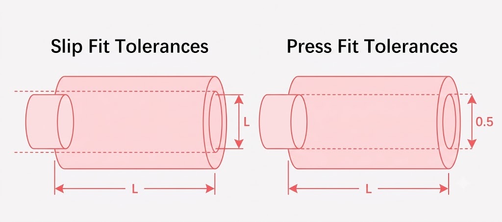
A slip fit and a press fit sit at opposite ends of the fit range.
| Slip Fit | Press Fit | |
|---|---|---|
| Size relationship | Hole larger than shaft | Shaft larger than hole |
| Assembly | By hand | Press or thermal methods |
| Movement | Slides or rotates | Locked in place |
| Disassembly | Easy | Difficult, may damage parts |
For interference calculations, press force, and how to choose between them, see our full guide to slip fit vs press fit.
A transition fit sits between the two. Depending on where each part lands in its tolerance band, it ends up with a small clearance or slight interference. Tight examples such as H7/k6 may need a mallet or a light press, so they are not true slip fits.
Common Applications
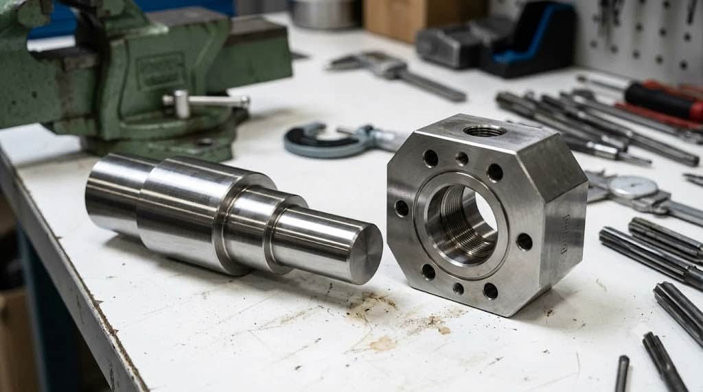
Slip fits appear wherever parts must be easily assembled by hand, come apart again, and stay aligned. The examples below show how clearance changes with the job.
Locating pins and fixtures
Dowel pins in slip-fit holes align two parts, so the bolts only have to clamp. Jigs, welding fixtures, and inspection fixtures rely on this because the pins can be pulled and reinserted many times without losing position. Two pins are enough. A third overconstrains the assembly. On blind holes, add a vent hole or a flat on the pin so trapped air does not make the fit hard to seat.
Heavy machinery and material handling
Hinge pins and pivot pins often run in plain bearings or bushings, and conveyor roller shafts work in dirty conditions on frames that flex. Looser tolerances are easier to hold, so classes such as H8/f7 are common. On a 25 mm shaft, that gives 0.020 to 0.074 mm of clearance, enough to tolerate debris and deflection without jamming.
Industrial automation
Linear motion systems such as guides and pneumatic cylinders need controlled clearance to keep friction low and wear even. Bore roundness and straightness matter as much as diameter here. A tapered bore will bind at one end of the stroke.
Precision instruments and optics
Focus barrels, lens mounts, and calibrated stages use tight fits such as H7/g6. The goal is minimal play without binding.
Serviceable parts
A bearing outer race, also called the outer ring, often sits in the housing with a slip fit so it can be replaced without damaging the bore. With a rotating shaft, the inner ring usually takes a tighter fit. Spigots, covers, and cartridge modules follow the same logic.
Designing Slip Fits for Precision CNC Machining Parts
A good slip fit is the loosest fit that still does the job. Tight tolerances cost more to machine and inspect, and they leave less room for error at assembly.
Start with function and environment
The typical clearance for a slip fit depends on the expected load and the operating environment. Write down the acceptable minimum and maximum clearance before choosing a class. A locating pin that must hold position within 0.020 mm cannot use a fit with 0.070 mm of maximum clearance. A conveyor shaft in a dusty frame does not need that precision at all. High operating temperature calls for more clearance, so thermal expansion does not cause binding.
Pick the class
Use the hole basis system for most machined parts. Reamers and boring bars cut fixed bore sizes, and it is easier to adjust a shaft on a lathe than to stock a reamer for every fit. H7/g6 is a sound default for precision work. On a 25 mm feature it gives 0.007 to 0.041 mm of clearance. Move to H8/f7 (0.020 to 0.074 mm) for warm, dirty, or long-engagement parts. H7/h6 has zero minimum clearance, so it is a tight fit that suits accurate location, not parts that turn or slide often.
Check the materials
Fit tables assume room temperature and matching materials. With mixed materials, thermal expansion changes the clearance, so calculate it at operating temperature. An aluminum shaft in a steel bore grows about 0.017 mm more than the bore for a 25 mm nominal size with a 60°C rise. That thermal growth is more than the entire minimum clearance of H7/g6. A steel shaft in an aluminum bore does the reverse and gains clearance as it heats, which can add vibration.
Also consider galling. Stainless steel and soft aluminum can seize under sliding contact when the clearance is tight and the surfaces are dry. Hardness matters too. Soft aluminum wears faster under repeated sliding, while hardened and ground steel shafts hold tight fits longer.
Set the surface finish
Surface finish affects effective clearance, because surface peaks use up part of the gap. For H7/g6, specify Ra 0.8 µm or better on both surfaces. At Ra 1.6 µm, the combined peaks can approach the whole minimum clearance, so H7/f7 is safer. A smoother finish also reduces friction during break-in.
Control form with GD&T
A bore measured correctly at two points can still be tapered or out of round, which eats the clearance and makes parts bind. Add cylindricity or straightness tolerances on long engagements. When two or more pins or bores must line up, use GD&T position tolerances tied to datums. They protect positional accuracy across the whole assembly.
Account for coatings
Anodizing adds thickness, and a fit can shrink to zero or turn into interference. Typical thickness is 0.5 to 2.5 µm for Type I, 5 to 25 µm for Type II, and 25 to 50 µm or more for Type III. On an H7/g6 fit with only 7 to 41 µm of clearance, a Type II or III coating can use up most of the gap. State on the drawing whether the fit applies before or after finishing. If after, machine the parts undersize to compensate.
Match tolerance to process
Standard turning and boring hold H7 bores and IT6 shafts with proper gauging. Reaming gives more consistent roundness than interpolated milling. Below roughly 0.010 mm of total clearance, grinding, honing, or air gauging may be needed, and cost rises quickly. Specifying tighter than the shop can hold leads to sorting and scrap.
Make the drawing clear
Use the ISO designation, such as Ø25 H7/g6. Add the surface finish, the finished condition (before or after coating), and what the first article report must show, such as actual bore diameter. This tells quality assurance exactly what to measure. Aria’s engineers check these callouts during DFM review and flag fit stack-ups before production.
