


Welding is a core technology in sheet metal fabrication for joining metal components. However, welding is not a flawless process. Various welding defects can form inside or on the surface of the weld metal. They can occur in processes such as Shielded Metal Arc Welding (SMAW), Gas Metal Arc Welding (GMAW), laser welding, and electron beam welding. Their types and likelihood depend on the process, material, joint design, welding parameters, and production conditions.
High-stakes applications impose stringent acceptance criteria. Weld acceptability must be assessed against the applicable standard, design requirements, and service conditions. This guide covers the main categories of welding defects, 19 common welding defects with their causes and remedies, and the testing methods used to identify welding defects. Understanding these defects early helps mechanical engineers, product designers, and procurement managers prevent production delays and control manufacturing costs.
What Is a Welding Defect?
A weld defect is an irregularity or discontinuity that compromises the structural integrity, safety, or appearance of a welded joint beyond allowable code limits.
Defects can sit inside the weld or on its surface. Surface defects can often be found by visual inspection. Internal welding defects usually cannot. They are typically found only through nondestructive testing (NDT), such as radiographic testing (RT) or ultrasonic testing (UT).
ISO 6520 classifies the irregularities that affect welds. Not every irregularity means rejection. Some stay within the limits of the applicable standard and are acceptable. Others exceed those limits, and the part is rejected. Preventing weld failure starts with knowing which is which.
Categories of Welding Defects
Welding defects can be classified by type or by location. ISO 6520-1 groups the geometric imperfections of fusion welds by type into six categories: cracks, cavities, solid inclusions, lack of fusion and penetration, imperfect shape and dimensions, and miscellaneous imperfections. Each category reflects a specific aspect of the welding process that directly impacts joint integrity and quality, and must be evaluated against clearly defined unilateral and bilateral tolerances. Just as choosing the right types of screw head for an assembly influences clamping and surface finish, inappropriate welding parameters, poor application techniques, or inadequate process control will generally lead to these imperfections.
Cracks
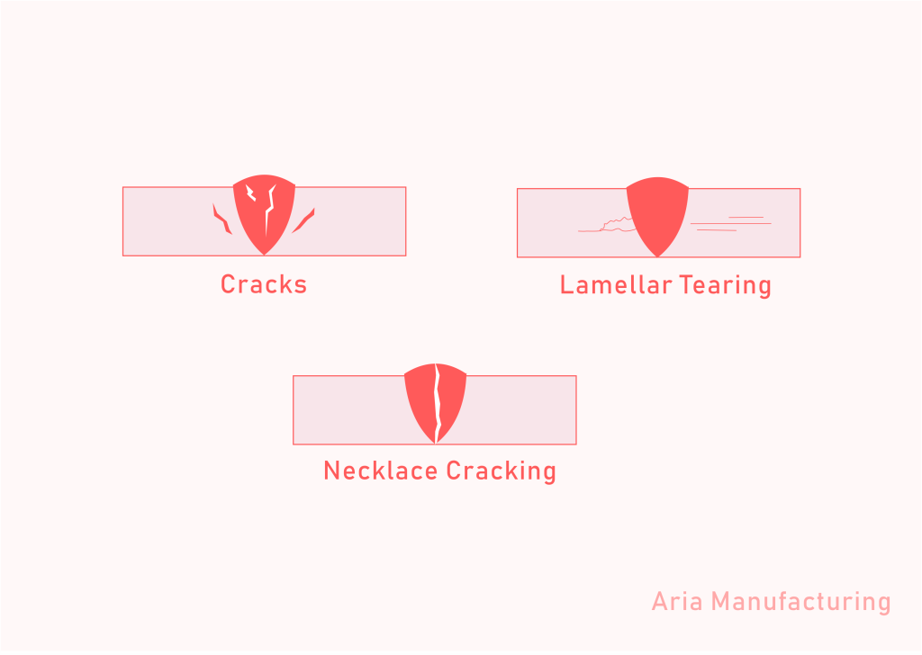
Cracks are linear fractures in the weld metal or the heat-affected zone. They are the most serious category of weld imperfection.
| Common Welding Defect | Description |
|---|---|
| Cracks | Linear fractures in the weld metal or heat-affected zone. |
| Lamellar Tearing | Step-like fracturing beneath the weld in steel plates. |
| Necklace Cracking | A defect associated with electron beam welding, linked to molten metal not flowing sufficiently into the weld cavity. |
Cavities
Cavities are voids left in the weld metal by trapped gas or by shrinkage during solidification.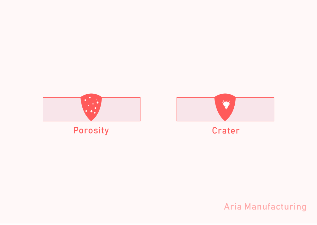
| Common Welding Defect | Description |
|---|---|
| Porosity | Tiny cavities trapped during weld pool solidification. |
| Crater | A depression or shrinkage cavity at the end of a weld bead. |
Solid Inclusions
Solid inclusions are foreign particles trapped in the weld metal.
| Common Welding Defect | Description |
|---|---|
| Slag Inclusions | Non-metallic particles trapped inside the weld metal. |
Lack of Fusion and Penetration
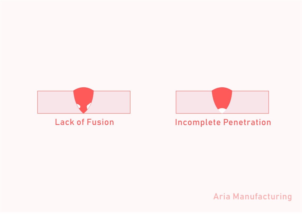
These imperfections are areas where the weld metal did not bond with the base metal or an earlier pass, or did not fuse through the joint root.
| Common Welding Defect | Description |
|---|---|
| Lack of Fusion | Weld metal failing to bond with the base metal. |
| Incomplete Penetration | Weld metal failing to fuse through the joint root. |
Imperfect Shape and Dimensions
Imperfect shape and dimensions are problems with the shape or size of the weld or the joint. They usually result from incorrect welding techniques, improper filler metal application, or poor fit-up. These issues directly affect the structural integrity and durability of the weld.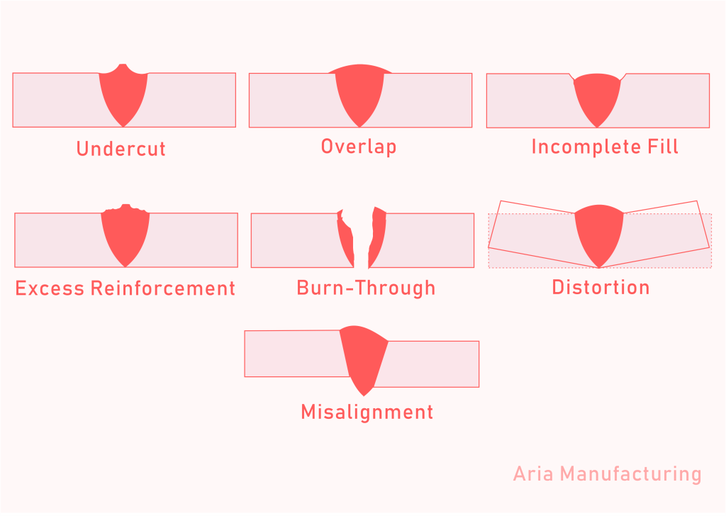
| Common Welding Defect | Description |
|---|---|
| Undercut | Groove melted into the base metal at the weld toe. |
| Overlap | Excess filler metal rolling over the weld toe without fusion. |
| Incomplete Fill | Weld metal failing to fill the joint cross section. |
| Excess Reinforcement | Excess filler metal creating a bead beyond profile limits. |
| Burn-Through | An open hole where the arc melts through thin sheet metal. |
| Distortion | Workpiece warping or bending from uneven heating and cooling. |
| Misalignment | Offset or height difference from improper initial part alignment. |
Miscellaneous Imperfections
Miscellaneous imperfections cover flaws that do not fit the other five groups. Many of them come from arc control, handling, and cleanup.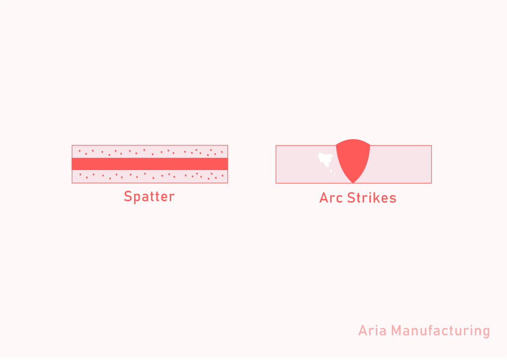
| Common Welding Defect | Description |
|---|---|
| Spatter | Molten metal droplets stuck to the base metal surface. |
| Arc Strikes | Localized thermal damage where the arc is struck outside the intended weld area. |
| Mechanical Damage | Dents, gouges, or tool marks on the weld or base metal. |
| Whiskers | Short electrode wire pieces protruding from the weld root. |
19 Common Types of Welding Defects
Undercut
Undercut occurs when the base metal at the weld toe melts away and leaves an unfilled groove along the edge of the weld, somewhat analogous to a recessed undercut feature in machining. This notch reduces the cross-sectional thickness of the base metal and creates a stress concentration point.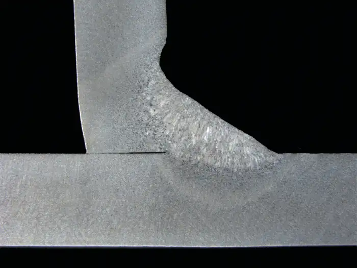
| Cause | Prevention | Remedy |
|---|---|---|
| Excessive welding current or arc voltage | Lower the welding current and arc voltage | Grind out the defective weld and reweld. |
| Travel speed is too fast | Slow down the travel speed to allow proper filling | |
| Improper electrode angle | Adjust the electrode to the proper angle for the joint |
Spatter
Spatter occurs when molten metal particles scatter and stick to the base metal surface around the weld. While it rarely weakens the joint itself, it creates a rough finish that interferes with coatings and requires extra cleanup.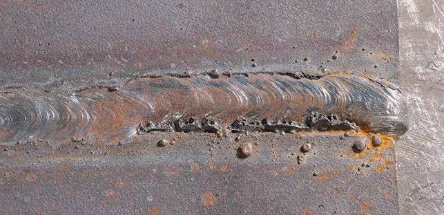
| Cause | Prevention | Remedy |
|---|---|---|
| Excessive welding current | Select an appropriate welding current | Remove spatter mechanically, adjust machine settings and shielding, and apply anti-spatter treatment to fixtures and consumables. |
| Arc length is too long | Shorten the arc length | |
| Incorrect polarity selection | Set the correct polarity for the filler metal | |
| Wrong shielding gas selection | Use the proper shielding gas and flow rate | |
| Metal surface contamination | Clean the metal surface thoroughly before welding |
Cracks
Welding cracks are linear fractures in the weld metal or the heat-affected zone (HAZ). They are among the most serious welding defects, because a crack can grow under load and lead to failure. Cracks can be classified in two ways.
By orientation and location, longitudinal cracks run parallel to the weld bead, and transverse cracks run across it. Crater cracks form at the end of the bead, where the arc stops.
By when they form, hot cracks appear during solidification. Cold cracks appear after the weld has cooled. They are linked to hydrogen and high restraint, and they can show up hours or days later.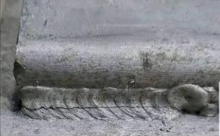
| Cause | Prevention | Remedy |
|---|---|---|
| High residual stress or joint restraint | Design joints to minimize restraint and select ductile base metals | Gouge or grind out the crack completely, re-weld using correct procedures, apply post-weld heat treatment if required, and investigate the root cause of hydrogen or restraint. |
| Inadequate preheat or interpass control | Preheat the base metal and control cooling rates | |
| Hydrogen absorption | Avoid hydrogen sources and use low-hydrogen consumables | |
| Rapid cooling rate | Adjust welding speed and current to control cooling | |
| Poor crater filling technique | Use proper crater-fill procedures |
Porosity
Porosity refers to tiny cavities or gas pockets formed when gases become trapped in the weld metal during the solidification of the weld pool. These voids weaken the overall mechanical strength and reduce the fatigue resistance of the joint.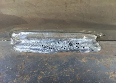
| Cause | Prevention | Remedy |
|---|---|---|
| Surface contamination (oil, grease, moisture, rust, or hydrocarbons) | Ensure proper cleaning of the base metal and prevent contaminants from entering the welding area | Grind out the porous section and reweld the joint properly. |
| Damp or contaminated electrodes, wires, or flux | Select appropriate, dry electrodes and filler materials | |
| Incorrect shielding gas type or flow rate | Use high-purity shielding gas and configure the flow meter to correct settings | |
| Excessive arc voltage or excessive gas flow | Maintain correct arc length and stable parameters |
Overlap
Overlap occurs when excess molten filler metal overflows or rolls past the edge of the weld toe or root without fusing to the base metal. This creates a sharp notch effect that can lead to stress concentration and joint failure under load.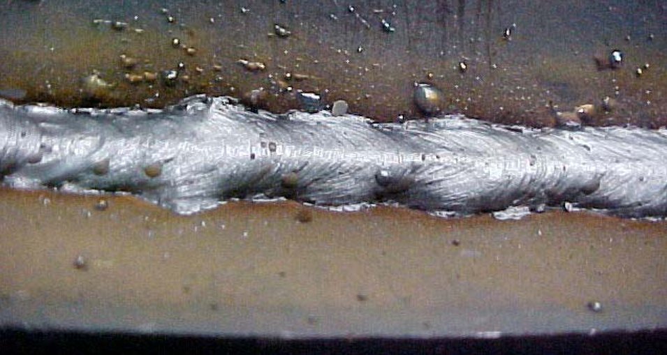
| Cause | Prevention | Remedy |
|---|---|---|
| Slow travel speed | Increase travel speed to prevent filler metal buildup | Grind the overlap off so it blends smoothly into the base metal, taking care to avoid deep grinding. If the imperfection goes deeper, remove it and reweld the area. |
| Improper electrode angle | Maintain a proper push or pull angle centered on the joint | |
| Incorrect current or voltage | Reduce excessive current intensity or balance voltage and wire feed speed | |
| Base metal contamination (rust, oil, scale, or burrs) | Thoroughly grind, wire brush, or solvent clean the base metal before welding |
Incomplete Fill
Incomplete fill occurs when the weld metal fails to completely fill the joint cross section, leaving a groove, depression, or low spot along the weld surface below the level of the adjacent base metal. This reduces the effective cross-sectional thickness of the weld and creates a weak point prone to stress concentration.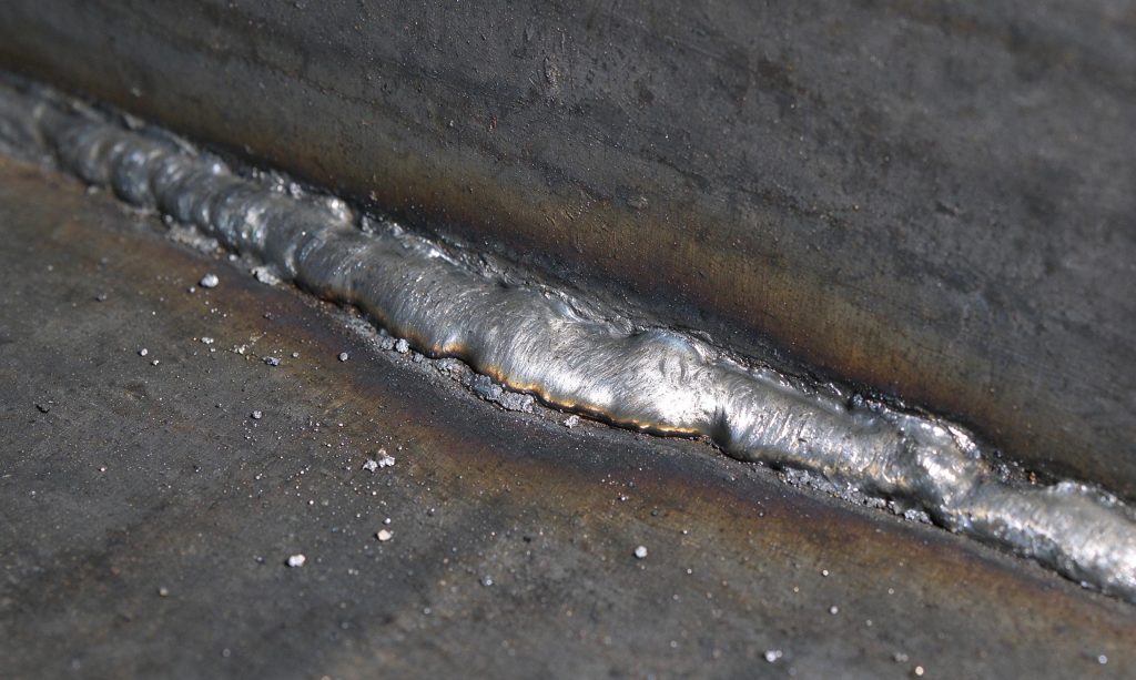
| Cause | Prevention | Remedy |
|---|---|---|
| Insufficient filler metal added to the joint | Add adequate wire or electrode volume during welding | Clean the area, grind or feather the low section, and apply an additional cover pass to fill the depression to the proper height. |
| Travel speed is too fast | Slow down the travel speed along the joint | |
| Low amperage or heat input settings | Increase the power input for proper penetration and fill | |
| Incorrect pass sequence | Use proper coverage passes or a weaving technique on wide grooves |
Excess Reinforcement
Excess reinforcement occurs when too much filler metal is deposited into a groove weld joint, creating a weld bead that extends beyond acceptable profile limits. This sharp transition at the weld toe increases stress concentration and reduces the fatigue life of the joint.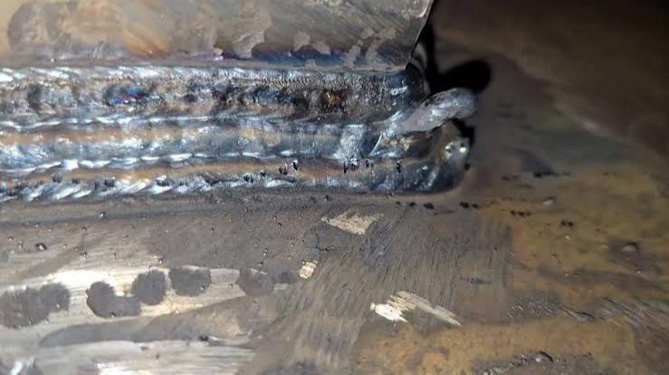
| Cause | Prevention | Remedy |
|---|---|---|
| Travel speed is too slow | Increase travel speed to distribute filler metal evenly | Mechanically remove the excess metal and grind it to a smooth transition without gouging the base metal. |
| Wire feed speed is set too high | Match amperage and voltage to the wire feed speed | |
| Incorrect welding parameters | Adjust welding parameters to ensure optimal bead profile | |
| Large gap left between workpieces | Align workpieces properly to prevent excessive joint gaps |
Burn-Through
Burn-through occurs when the welding arc or flame completely melts through the thickness of the base metal, leaving an open hole or crater-like void. It is common in thin sections and unsupported root passes, where the molten pool cannot be adequately supported or controlled.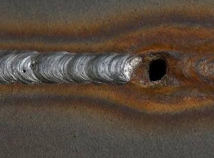
| Cause | Prevention | Remedy |
|---|---|---|
| Excessive root gap or large spacing between parts | Eliminate large root gaps before striking an arc | Grind away slag, heavy oxidation, or distorted edges around the hole. Depending on the material and joint, one option is to place a copper backing behind the opening and bridge the gap with short tack welds, lower amperage, and a skip-cooling method. |
| Welder settings are too high for the metal gauge | Avoid excessive amperage or high welder settings | |
| Travel speed along the joint is too slow | Move faster along the joint to prevent heat saturation at a single spot |
Mechanical Damage
Mechanical damage in welding refers to physical, post-weld, or handling-related trauma, such as external dents, gouges, scratches, or tool marks. This damage compromises the structural integrity, geometry, or protective surface of the weld and base metal. These marks can create stress concentration points and reduce corrosion resistance.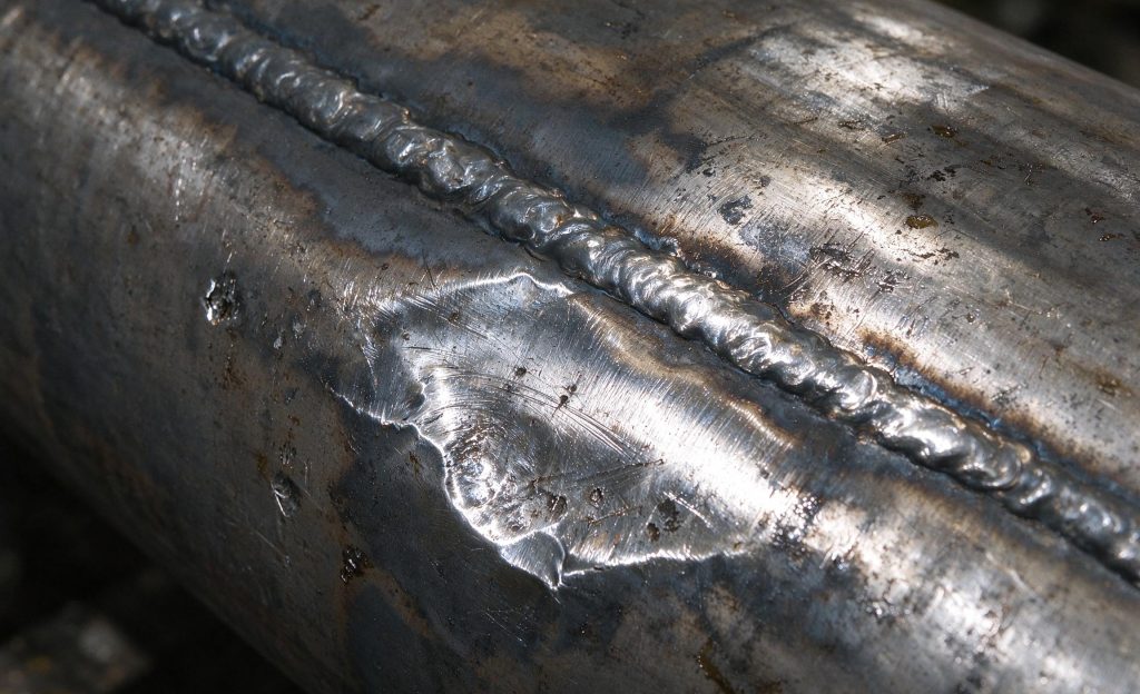
| Cause | Prevention | Remedy |
|---|---|---|
| Applying excessive force during chipping or slag removal | Use controlled force and proper tools during post-weld cleanup | Smooth out minor abrasions through careful grinding without violating minimum wall thickness; excavate deep gouges and deposit a repair weld. |
| Improper handling of electrode holders or clamps | Handle electrode holders and ground clamps carefully after welding | |
| Inefficient or careless use of grinders and rigging | Install protective rigging such as soft copper or polymer pads |
Arc Strikes
An arc strike is localized damage caused when the arc is struck outside the intended weld area. The damage is thermal, not mechanical. Rapid heating and cooling at the spot can produce hard zones and cracking, especially in susceptible steels. Arc strikes should be assessed separately from scratches or handling damage.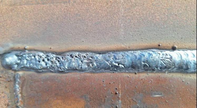
| Cause | Prevention | Remedy |
|---|---|---|
| Failing to engage the arc properly with the metal | Strike the arc within the weld groove before starting | Grind or sand the spot smooth, then test it for cracks. If cracks are found, remove them and repair with a qualified repair procedure. Inspect the repair like any other weld. |
| Loose ground connection or damaged welding cable | Tighten the ground clamp securely and replace damaged cables | |
| Electrode touching the base metal away from the joint during setup or repositioning | Stay aware of the live electrode, and shield nearby surfaces with fire blankets in hard-to-reach areas |
Distortion
Welding distortion is the warping, bending, or twisting of a workpiece caused by uneven heating and cooling across the welded joint. It can take several forms, including longitudinal shrinkage, transverse shrinkage, angular distortion, bowing, buckling, and twisting.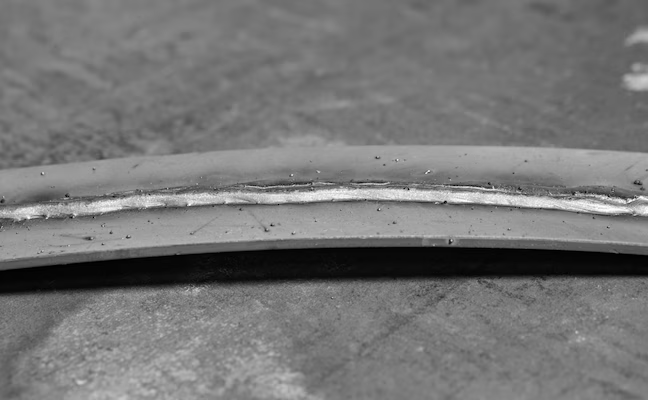
| Cause | Prevention | Remedy |
|---|---|---|
| Excessive heat input | Lower heat input and use smaller weld bead sizes | Correct the distortion by mechanical straightening, such as pressing, or by localized heating. The method depends on the material and the part. |
| Lack of mechanical restraint | Add clamps, jigs, and fixtures to hold parts in alignment | |
| Improper welding sequence | Use backstep welding, skip welding, or alternate sides of the neutral axis to balance residual stress | |
| Long continuous runs on thin sheet metal | Break up long welds into shorter segments and select suitable filler metals |
Misalignment
Misalignment, also known as high-low or offset, occurs when two pieces of metal or pipe are improperly aligned before arc ignition, resulting in an offset or height difference across the joint. This structural flaw disrupts the smooth load path and creates significant stress concentration points.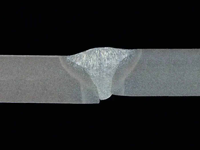
| Cause | Prevention | Remedy |
|---|---|---|
| Improper metal alignment or workpieces not clamped securely before welding | Use internal or external alignment clamps, spacers, and backup bars | Machine or taper mismatched ends to match tolerances, or cut out the misaligned section, re-prepare the joint, and reweld using proper alignment fixtures. |
| Lack of adequate tack welding to hold parts in place | Apply proper tack welds at regular intervals prior to full welding | |
| Dimensional variation or warping in raw stock components | Inspect material dimensions and straighten components before assembly | |
| Poor handling or incorrect fit-up technique | Establish a standardized fit-up and verification checklist before striking the arc |
Crater
A crater is a depression, void, or shrinkage cavity formed at the end of a weld bead when the arc breaks and the molten pool solidifies too quickly. This localized thinning weakens the end of the weld and frequently serves as a starting point for crater cracks.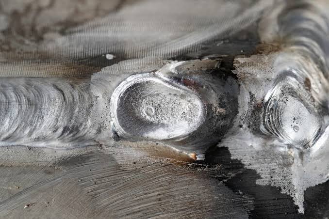
| Cause | Prevention | Remedy |
|---|---|---|
| Sudden termination of the welding process | Gradually decrease the welding current (slope-out), pause or double back slightly before breaking the arc to fill the crater properly, and maintain shielding gas coverage. | If crater cracks or deep pits are already present, grind out the defect completely before re-welding the joint. |
| Loss of shielding gas protection | Maintain post-flow shielding gas until the molten pool solidifies completely. | |
| Improper crater fill technique | Utilize a remote control current-decay feature or manual pause-and-backfill method. |
Slag Inclusions
Slag inclusions occur when non-metallic particles, such as flux or oxide residues, become trapped inside the weld metal, at the weld interface, or between multi-pass layers instead of floating to the surface. This creates internal discontinuities that reduce the effective cross-sectional area and weaken the structural integrity of the joint.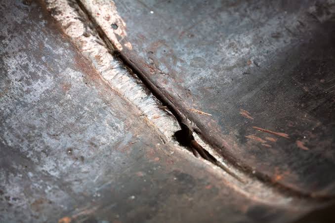
| Cause | Prevention | Remedy |
|---|---|---|
| Inadequate heat input or low amperage | Increase heat input and amperage to ensure proper fusion and allow slag to float out | Grind out the slag inclusion completely and reweld the joint properly. |
| Joint design is too narrow or restricted | Redesign the joint to provide sufficient clearance for proper weld puddle manipulation | |
| Poor interpass cleaning (residual slag remaining from previous passes) | Thoroughly clean slag between weld passes using a wire brush, chipping hammer, or grinder | |
| Incorrect electrode angle or travel speed | Use the correct electrode angle and maintain a steady travel speed to prevent trapping slag |
Lack of Fusion
Lack of fusion occurs when the deposited weld metal fails to properly bond with the base metal or a previous weld pass, leaving an unbonded interface. This critical structural defect creates a sharp planar discontinuity that severely reduces load-bearing capacity and fatigue resistance.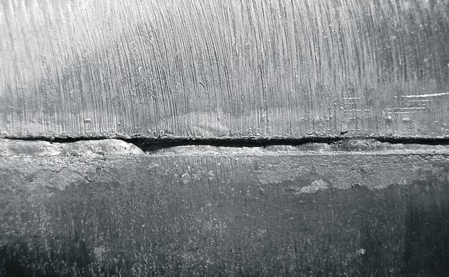
| Cause | Prevention | Remedy |
|---|---|---|
| Low current or heat input | Increase welding current and heat input to ensure complete melting of the joint faces | Completely remove the defective weld area by grinding or gouging, and reweld using proper parameters and technique. |
| Travel speed is too fast | Adjust travel speed to allow sufficient heat transfer and proper puddle wetting | |
| Incorrect torch or electrode angle | Aim the arc properly at the joint intersection to fuse sidewalls and root | |
| Arc length is too long | Maintain a short, stable arc length to concentrate heat | |
| Surface contamination (rust, scale, oil) | Clean base metal thoroughly before welding to remove oxides and impurities |
Incomplete Penetration
Incomplete penetration occurs when the weld metal fails to completely melt and fuse into the root of the joint, leaving an unbonded gap or root opening. This creates a severe structural weakness, reduces load-bearing capacity, and acts as a significant stress concentration point.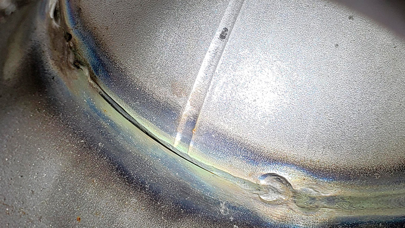
| Cause | Prevention | Remedy |
|---|---|---|
| Improper welding technique or incorrect electrode angle | Use proper welding technique and ensure correct joint fit-up | Completely remove the defective weld area by grinding or gouging, improve joint fit-up, and reweld using proper parameters and heat input. |
| Insufficient heat input or low amperage | Increase welding current and voltage to ensure adequate root penetration | |
| Travel speed is too fast | Reduce travel speed to allow sufficient heat transfer into the root | |
| Root gap or joint opening is too small | Ensure proper root opening and root face dimensions during joint preparation |
Lamellar Tearing
Lamellar tearing occurs beneath the weld in rolled steel plate weldments, characterized by a stepped, terraced, or fibrous woody appearance. It develops when high weld shrinkage and residual stresses pull the plate in the through-thickness direction, separating non-metallic inclusions along the rolling planes; proper edge preparation and beveling of plate joints can help reduce this restraint.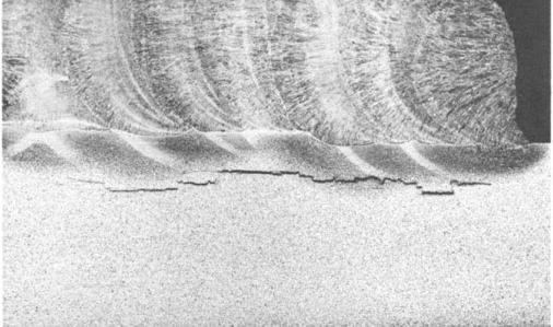
| Cause | Prevention | Remedy |
|---|---|---|
| Poor material selection (high sulfur or non-metallic inclusions in rolled steel plate) | Specify low-sulfur, clean steels or plates tested for through-thickness ductility (Z-grade steel) | Completely gouge or grind out the weld metal and torn base metal, then rebuild the joint using controlled preheat, minimal weld volume, and a balanced pass sequence. |
| High through-thickness restraint and weld shrinkage stresses | Redesign joints to minimize through-thickness tensile stress and reduce weld volume | |
| Depositing weld metal directly onto susceptible plate surfaces | Apply a ductile buttering layer onto the susceptible plate face before completing the main joint |
Whiskers
Whiskers, typically occurring in the GMAW (MIG) welding process, refer to short pieces of electrode wire protruding from the root side of the weld. This defect happens when the wire feed speed outpaces the melting rate, pushing unconsumed electrode wire through the root gap of the joint.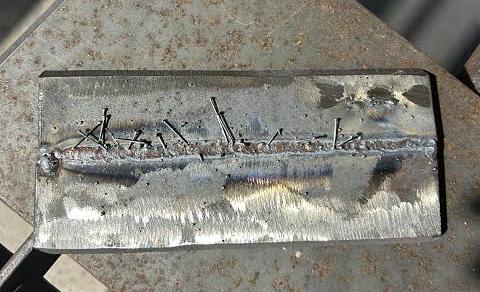
| Cause | Prevention | Remedy |
|---|---|---|
| Electrode wire extending too far ahead of the molten pool (wire feeding faster than consumption rate) | Trim the wire ball or excess wire tip before striking an arc and adjust machine parameters | For isolated whiskers, grind out the affected spot and reweld. For multiple whiskers along the root bead, grind out the full thickness of the affected weld section and perform a complete re-weld. |
| Excessive wire feed speed relative to voltage and current settings | Match wire feed speed accurately with proper welding voltage and amperage | |
| Travel speed is too fast during the root pass | Maintain a controlled, steady travel speed to allow proper consumption of the filler wire |
Necklace Cracking
Necklace cracking is a defect associated with electron beam welding (EBW). Published studies describe it as a kind of cold shut, an unfused discontinuity that forms when the weld solidifies improperly. Reference articles also link it to molten metal that does not flow sufficiently into the weld cavity, which results in incomplete penetration.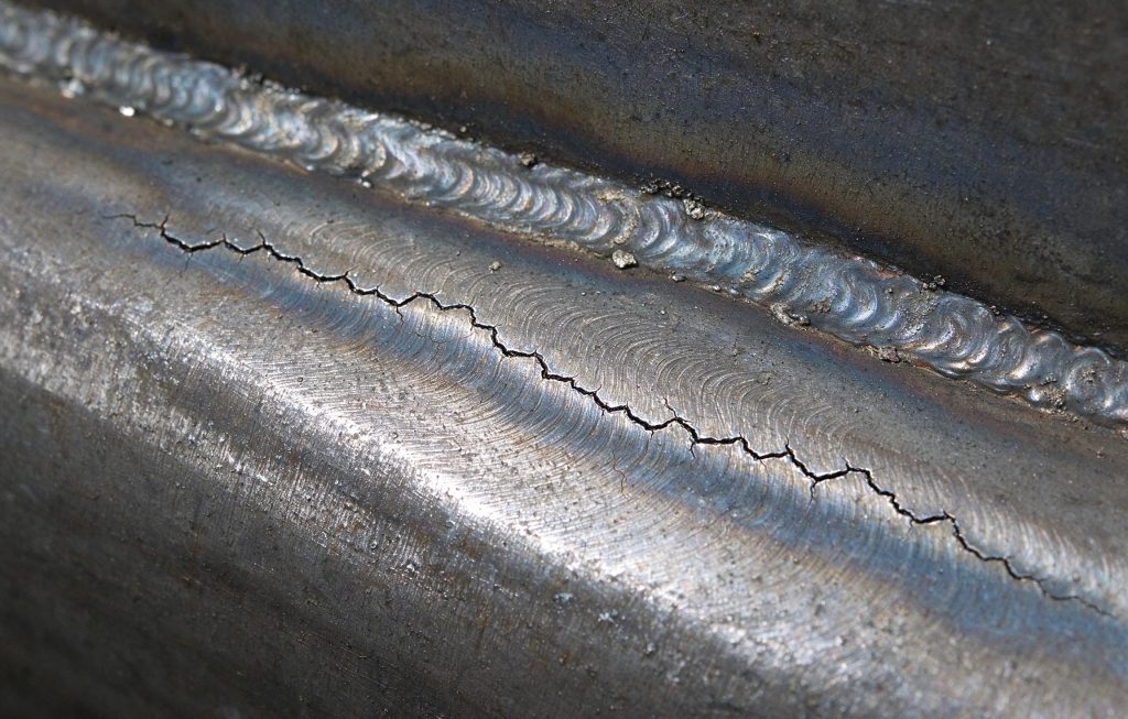
| Cause | Prevention | Remedy |
|---|---|---|
| Improper welding technique | Apply proper welding technique and procedure | Remove the cracked section and reweld it under an approved repair procedure. Inspect the repair like any other weld. |
| High operating speed in electron beam welding | Use a constant speed to achieve uniformity | |
| Material and welding conditions unsuited to electron beam welding (reported in stainless steel, carbon steel, tin, and nickel-based alloys) | Select materials suited to electron beam welding |
How to Distinguish between Welding Discontinuity and Welding Defects
A welding discontinuity is any interruption in the typical physical, mechanical, or metallurgical structure of a weldment. Porosity, a small slag inclusion, or a slight undercut are all discontinuities.
The difference between a discontinuity and a defect is the acceptance limit. A discontinuity that stays within the limits of the applicable quality standard is acceptable. It needs no further action. A discontinuity that fails to satisfy the applicable acceptance criteria is a defect. A defect is unacceptable and rejectable. The part must be repaired or reworked, or scrapped if repair is not possible, just as out-of-spec press-fit tolerance conditions can force costly rework in mechanical assemblies.
How to Detect Welding Defects
Welding defects are found through systematic inspection and testing. These evaluation methods fall into two primary categories: nondestructive testing and destructive testing.
Non-Destructive Testing
Nondestructive testing (NDT) allows inspectors to examine a weld for weld discontinuities without damaging the component. This is critical in high-volume production environments where batches of parts must be tested while keeping the parts fully usable afterward.
NDT is typically performed using visual inspection, liquid penetrant testing, magnetic particle testing, eddy current testing, ultrasonic testing, acoustic emission testing, or radiographic testing. Visual inspection serves as the essential first step. Liquid penetrant testing detects surface-breaking discontinuities in suitable nonporous materials. Magnetic particle testing detects surface and near-surface discontinuities in ferromagnetic materials. Ultrasonic and radiographic testing are utilized to detect internal welding defects located deep within the welded structure.
Destructive Testing
Destructive testing requires removing, sectioning, deforming, or fracturing a specimen. Mechanical tests evaluate properties such as strength and ductility, while macrographic examination reveals weld geometry, penetration, fusion, and discontinuities on a prepared cross-section. This method is frequently implemented alongside NDT to significantly reduce welding defects in production by identifying exact process corrections needed.
Several destructive methods are used to evaluate the weld metal, including tensile strength testing, guided bend testing, free bend testing, back bend testing, nick-break testing, and macrographic examination of an etched weld cross-section. Similar mechanical tests are also applied to validate the durability of plastic joints such as snap-fit connections in injection-molded parts, screw boss design in injection-molded parts, and the boss regions that receive self-tapping screws for plastic components assembled with self-tapping screws in plastic injection-molded parts.
