

 EU
EUSnap fits are all around us and for all the right reasons. Snap-fit joints are easy to manufacture, cheap, and join two parts easily without any exposed joints, or bolt mechanics. Plastic fittings often employ snap joints, and you likely encountered these early on through the release buckles on school bags.
The purpose of this article is to provide essential information about snap-fit design. This will enable you to create snap-fit connections for your project.
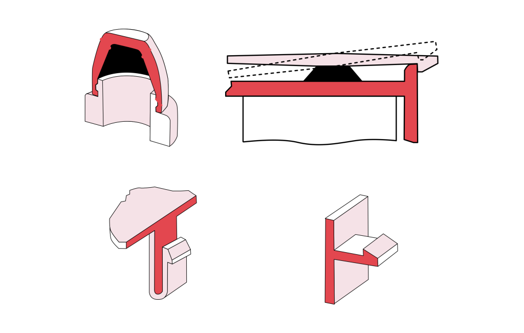
What Is A Snap-Fit?
A snap-fit is a fastening method used in product design to connect plastic parts without screws, bolts, or adhesives. It works by using snap-fit joints, such as hooks or heads, where a protruding feature on one component deflects and locks into a recess on the other. This allows fast assembly and disassembly without special tools or extra fasteners.
Snap-fit joints fall under the assembly category and are often considered an extension of the part itself. The technique joins flexible components by inserting an interlocking snap fit feature on one of the male and female components into a cavity on the mating part. Successful attachment depends on enough flexibility in the interlocking features to allow bending during insertion and a secure lock once fully seated.
Snap fit functionality relies on the elastic behaviour of the material. Plastic snap fit joints work because thermoplastics can deflect under load and return to their original shape without permanent deformation. This makes snap fit designs a practical, cost-effective alternative to mechanical fasteners in plastic product assemblies.
How Do You Design a Snap-Fit Joint?
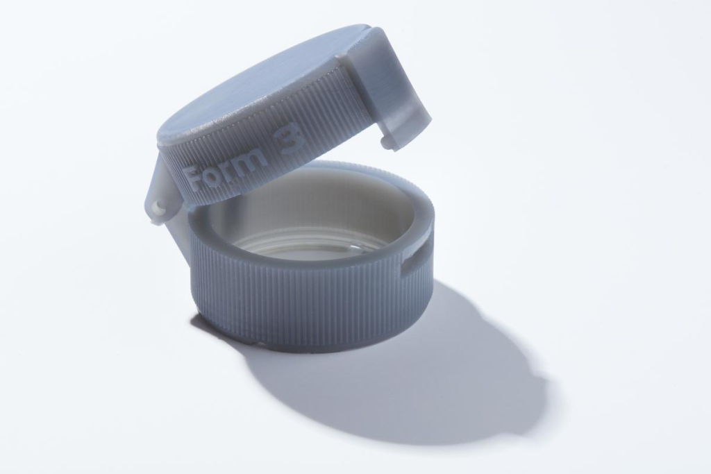
Designing a functional snap-fit joint means balancing geometric dimensions, material limits, and manufacturing feasibility. The process starts with selecting the right joint geometry for your application.
A cantilever snap-fit uses a flexible beam with a tapered hook and suits straight push-in assembly. An annular snap-fit relies on circular ridge deformation, as seen in bottle caps, and works best for cylindrical components. A torsion snap-fit uses rotational twisting force and is common in frequently opened latches and lids.
Once the geometry is set, the next step is calculating strain and deflection limits. The deflection strain during insertion must stay below the material’s allowable yield strain. A tapered beam profile, thick at the base and thin at the tip, helps distribute stress evenly along the beam length and prevents snap-off during installation.
Retention and engagement angles also need careful attention. The entry angle should fall between 30° and 45° to keep insertion force low and smooth. The exit angle controls whether the joint is reusable or permanent. Setting it around 45° allows easy disassembly for detachable joints. Setting it at 90° with a perpendicular undercut creates a permanent interlock.
Material selection ties everything together. Ductile thermoplastics such as ABS, Nylon (PA), or Polypropylene tolerate repeated bending without fatigue failure. For injection moulding, position the joint parallel to the mould opening direction. If that is not possible, add lifters or sliders to avoid complex tooling undercuts. This keeps tooling cost down and supports high-volume production.
Types of Snap Fit Joints
Annular Snap Fit Joints
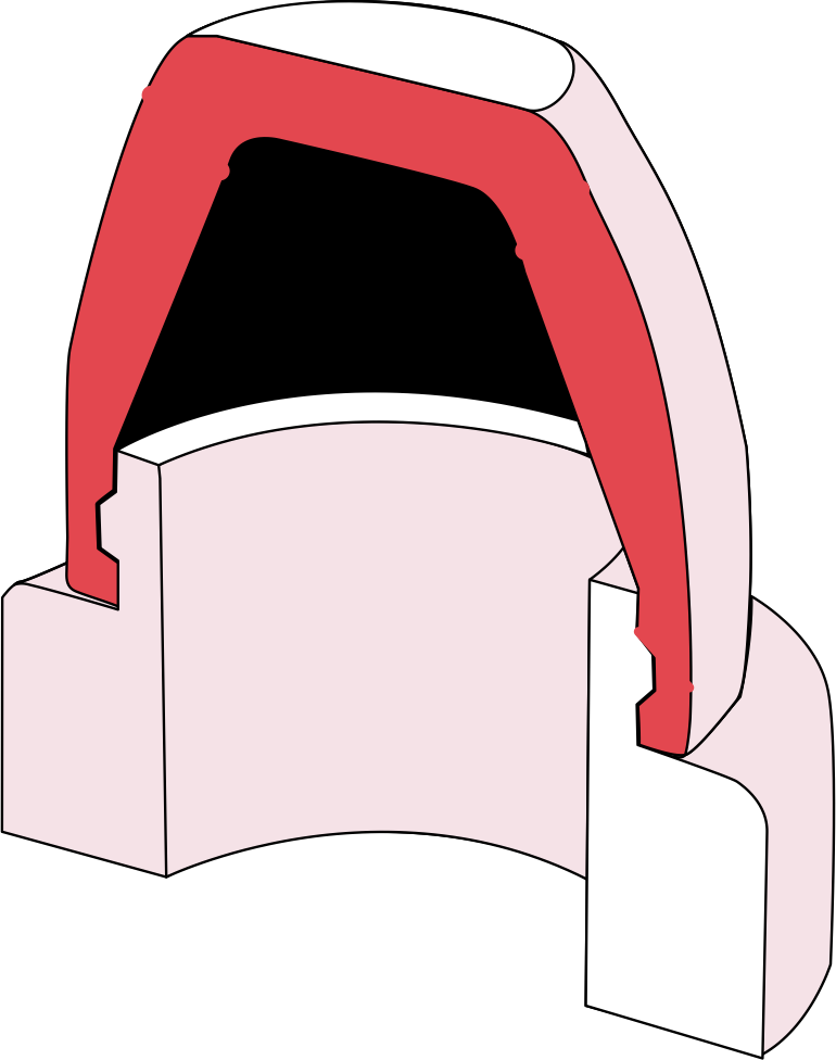
Annular snap-fit joints provide continuous 360° circumferential engagement, making them the standard choice for cylindrical assemblies. The joint works by pushing a circular ridge or bead on one component over a matching groove on the mating part. During insertion, the outer wall undergoes brief hoop expansion and then contracts back to lock into the groove.
The return angle determines whether the joint is reusable or permanent. A return angle around 45° creates a secure latch that can still be pulled apart without damage, suitable for reusable covers and caps. As the angle increases beyond 45°, retention force rises sharply. A 90° perpendicular return angle produces an irreversible lock that cannot be separated without breaking the assembly.
The main advantage of annular snap fits is uniform stress distribution across the entire perimeter. This gives the joint multi-directional holding power rather than relying on a single engagement point like a cantilever. Typical applications include plastic bottle caps, pen caps, quick-connect hose fittings, and cylindrical sensor enclosures.
Torsional Snap Fit Joints
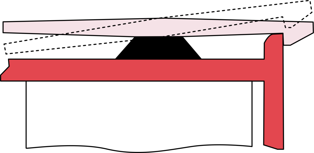
A torsion snap-fit joint uses torsional beam twisting rather than simple flexural bending to secure mating components. The design features a lever arm attached to a cross-shaft. When axial force is applied during assembly, the shaft twists and the retention hook snaps over the mating edge. Stored torsional spring force then locks the connection in place.
The mechanism works like a spring-loaded fulcrum beam. Pressing the release lever rotates the beam and instantly disengages the retention hook for tool-free removal. This makes torsion snap fits well suited for high-cycle latching where repeated assembly and disassembly must not wear down the joint geometry.
Common applications include hinged container lids, spring-loaded battery compartments, field-serviceable electronic enclosures, and quick-release access panels.
Cantilever Snap Fit Joints
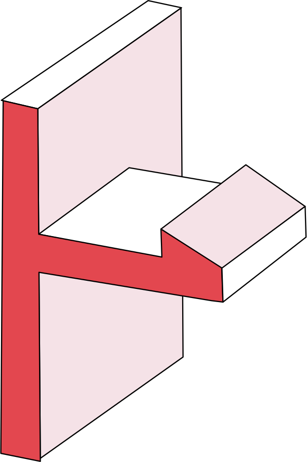
A cantilever snap-fit joint is the most widely used snap-fit design in plastic product engineering. It consists of a flexible overhang beam with a tapered or chamfered hook at its free end. During insertion, the chamfered lead angle slides along the mating edge and forces the beam to deflect. Once the hook clears the obstruction, the beam springs back into a matching undercut to form a positive mechanical interlock.
Tapering the beam from a thick base to a thinner tip distributes bending stress evenly along its length and prevents strain concentration at the root. The joint can be engineered for non-destructive reuse by adding an exit chamfer, or designed as a permanent lock using a 90° perpendicular retention angle.
Cantilever snap fits are economical and straightforward to mould in thermoplastics such as ABS, Nylon (PA), or Polycarbonate. They provide reliable fastener-free assembly with low insertion force. Common applications include electronic housing enclosures, battery cover doors, automotive dashboard trim clips, and consumer appliance shells.
U-Shaped Snap Fit
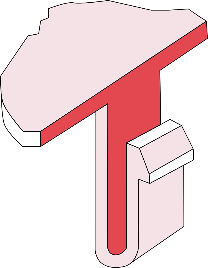
A U-shaped snap-fit joint is a modified cantilever design where the flexible beam folds back on itself in a hairpin curve to form a U-profile. This geometry extends the effective beam length within a compact footprint. Bending stress distributes across the curve rather than concentrating at a single root, which lowers overall strain during deflection.
The retention hook sits on the outer leg of the U-beam instead of at the tip of a straight cantilever. This changes the engagement direction so the joint can lock or release without a long linear sliding distance. The reduced insertion force and spread-out stress make U-shaped snap fits resistant to localised material fatigue over repeated assembly cycles.
Typical applications include TV remote battery covers, handheld device enclosures, hinged access doors, and other compact consumer electronics that require frequent opening and closing.
L-Shaped Snap Fit Joints
An L-shaped snap fit is the simplest form of cantilever snap-fit joint. The beam extends straight out from the base wall and ends with a short hook turned at a right angle, forming a distinct L-profile. The effective beam length equals the actual physical length of the arm because the beam does not fold or curve back on itself.
This straightforward geometry makes L-shaped snap fit joints the easiest to mould. It is also the most compact option when the part has enough clearance for a straight beam path. However, a straight beam with no taper concentrates bending stress at the root where it meets the wall. Generous fillets at this junction are critical to prevent stress cracking in L-shaped snap fit designs. A fillet radius of at least 0.5 times the wall thickness is recommended.
L-shaped snap fits work best in low-cycle or permanent assemblies where repeated disassembly is not expected. For joints that need to survive frequent opening and closing, a U-shaped or tapered cantilever design will distribute stress more effectively and offer a longer fatigue life. Typical applications for L-shaped snap fit joints include internal cable routing clips, circuit board retainers, and single-use packaging closures where the joint only needs to engage once during final assembly.
Snap Fit Design Calculations
σmax = mc/I
where M is the maximum bending moment
C is the distance from the point of interest to the neutral axis
I is the moment of inertia
Snap-fit design is incomplete without calculating the fatigue stress, maximum stress, deflection force and many other factors that eventually decide the dimensions of the snap fit joint. While there are many snap fit shapes, I will show a sample calculation for the cantilever snap joint and provide the formulas for other prominent snap fits.
There are two ways to design snap fit joints. You can either choose the material first and adjust the dimensions of your snap fit design accordingly or choose the dimensions first and find a material that can fit the calculated dimensions.
Cantilever Snap Joints
Designing a cantilever snap-fit joint requires calculating deflection, strain, and bending stress. These values determine whether the beam can flex during insertion without exceeding the material’s yield limit. Finite element analysis is commonly used to validate these calculations for complex geometries where simplified beam equations lose accuracy.
The maximum bending stress is given by
- σmax = mc/I
- where M is the maximum bending moment
- C is the distance from the point of interest to the neutral axis
- I is the moment of inertia
The maximum strain is given by
- ε = M/IE
- where E is Young’s modulus of the material
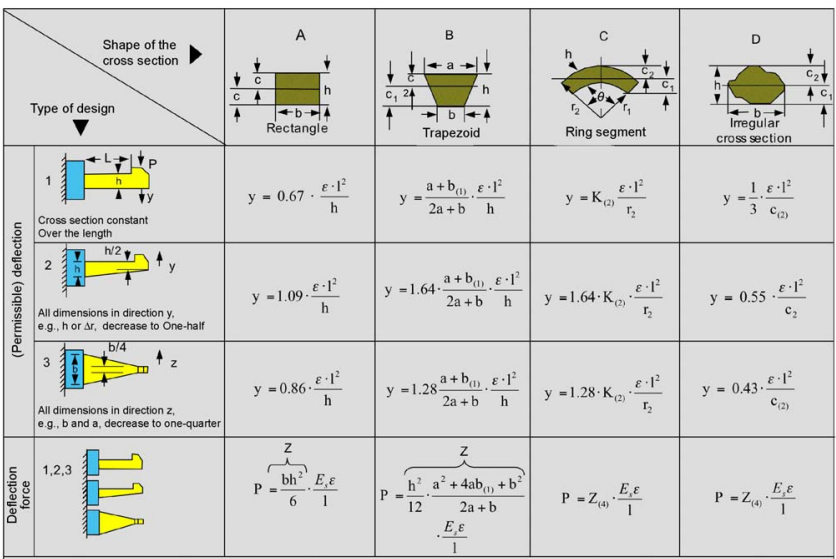
For a constant cross sectioned beam the deflection is given by
- y=0.67 * ει²/h
- where l is the length of the beam
- h is the thickness at root
And the deflection force is given by
- P =bh²/6 • Es ε/ι
- where b is the width at root
- Es is the secant modulus
Sample Calculation
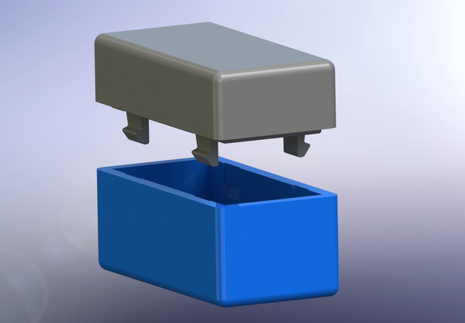
Suppose you are designing snap fits with cantilever beams of a constant cross section beam. You have the arm length (l) = 20 mm,
- Width (b) = 10 mm
- Undercut (y) = 3 mm,
- and An angle of inclination of 30°
You’re supposed to calculate the thickness of the arm and the recommended deflection force for an ABS material
- y= 0.67 * ει²/h
- h= 0.67 * ει²/y
- h= 0.670 • 0.25 • 20² / 3
- h= 89.33mm
Use the deflection force equation
- P= bh²/6 • Es ε/I
- Es= 1350 N/mm²
- P= 102 • 23²/6 * 13500 • 0.25/20
- P= 13.98 N
To find the mating force use this equation
- W=P • μ+tan(σ)/1-tan(σ)
- W=13.98 • 0.72+tan(30)/1-tan(30)
- W=42.91 N
Symbols
- y = (permissible) deflection (=undercut)
- E = (permissible) strain in the outer fiber at the root
- l = length of arm
- h = thickness at root
- b = width at root
- c = distance between outer fiber and neutral fiber (center of gravity)
- Z = section modulus Z = I c, where I = axial moment of inertia
- Es = secant modulus
- P = (permissible) deflection force
- K = geometric factor
Torsion Snap Joints
The shear modulus is given by
- G=Es/2(1+ν)
- where G is the shear modulus
- Es is the secant modulus
- ν is the Poisson’s ratio
The deflection force is given by
- P • ι= γ GIp /r
- where γ is the shear strain
- Ip is the polar moment of inertia
- W=P +tan(σ)/1-tan(σ)
- W=13.98 • 0.72+tan(30)/1-tan(30)
- W=42.91 N
Annular Snap Joints
Annular snap fit joints are used to join symmetrical round parts. In most annular snap fit design, at least one of the components is rigid. Having two elliptic or circular parts which are prone to easy deformation can result in smaller force on the material and in turn a larger undercut. The formulas for annular snap fits are given as follows
Transverse force is given by
- P= y • d • Es • X
- where y = undercut
- d = diameter at the joint
- Es = secant modulus
- X = geometric factor
Mating force is given by
- W=P • μ+tan(σ)/1-tan(σ)
- where μ = coefficient of friction
- α= lead angle
Snap Fit Design Best Practices
Snap fit joint designs do not end with calculations and material selection. Implementing proper geometric features addresses common failure modes and ensures consistent retention force across production runs.
Add Fillets
Sharp corners at the beam root are the leading cause of stress concentration in snap-fit joints. Adding a fillet at this junction spreads the load over a larger area and significantly reduces the risk of cracking. A fillet radius of at least 0.5 times the wall thickness is a practical starting point. For high-cycle joints, increasing that to 0.6 or above provides an extra margin against fatigue failure.
Taper
A tapered beam, thick at the root and thin at the tip, distributes bending strain more evenly along its length. A uniform cross-section concentrates strain at the root, which can exceed the allowable limit and cause the beam to snap. Tapering also uses less material per joint, reducing unit cost in high-volume injection moulding production.
Add Lugs
Almost all high-quality parts have lugs. Lugs are tiny protruding connecter elements that help with aligning two mating parts. Proper alignment prevents the hook from catching at the wrong angle, reduces assembly jam-ups on the production line, and transfers part of the operational shear load away from the flexing beam.
Increase Width Of Hook
Widening the hook distributes retention force across a larger contact area and increases the joint’s resistance to pullout loads. This is especially important for cantilever snap fits in load-bearing applications where the joint must resist vibration or sustained tension. As a general guide, the hook width should match or exceed the beam width to avoid creating a weak point at the transition.
Fatigue Life
Fatigue failure occurs when snap-fit joints are flexed through too many assembly and disassembly cycles. Micro-cracks form at stress concentration points, typically the beam root, and propagate until the beam fractures. Selecting thermoplastics with high yield and tensile strength, such as Nylon (PA66) or Acetal (POM), and adding root fillets to reduce stress concentration both lower the risk of fatigue failure.
Most Common Applications of Snap Fit Design
Snap-fit joints appear across a wide range of industries and product types. Integrating retention features directly into the moulded geometry eliminates external hardware, lowers assembly costs, and delivers a clean, seamless finish.
Some of the common uses of snap fit design are mentioned below.
Toys: Toys need to be light, cheap and mass-produced. Having fasteners that can be part of the toys mold is ideal and snap fit joints are used for this reason.
Pens: Pen caps are a classic example of an annular snap fit. The circular ridge uses circumferential hoop tension to hold the cap securely while allowing easy removal.
Strap buckles: Buckles on bags, tie-down straps, and camping gear use snap-fit joints to create a secure, tool-free connection that can be released under load.
Enclosures: Many electronic enclosures like USB hubs and ethernet boxes use snap-fit joints, and they can also give consumer products a cleaner appearance by hiding fasteners.
Lids and covers: Battery covers, storage compartment lids, and access panels frequently use U-shaped snap fittings for quick opening and closing over repeated cycles.
3D printing designs: Snap fits are well suited to 3D printed components because most prints use plastics or resins. 3D printing allows rapid prototyping of snap-fit geometry before committing to injection mould tooling. For thin-walled prints, snap fits often perform better than screwed fasteners, which risk splitting the material at the bolt hole.
Advantages and Disadvantages of Snap Fit Design
Pro
Other than the simplicity of making snap fit joints, they
- Simplicity in Manufacturing: Snap fit joints are straightforward to produce, requiring minimal additional processes or components.
- Tool-Free Assembly and Disassembly: They allow for easy assembly and disassembly without the need for special tools, making them user-friendly.
- Durability: When designed with accurate calculations and tolerances, snap fit joints can be long-lasting and reliable.
- Aesthetic Appeal: These joints can be seamlessly integrated into the design, hidden from view, enhancing the overall appearance of the product.
- Cost-Effective: Snap fit designs are economical, as they typically require no extra materials beyond the plastic being used.
Con
- Limited Strength: Snap-fit joints hold parts through elastic retention rather than clamped preload. They cannot match the mechanical strength of bolted or screwed connections and are not suited for high load-bearing applications.
- Wear and Tear: Each assembly and disassembly cycle stresses the beam and retention features, gradually reducing holding force. Once assembled, the connection is also difficult to inspect visually for quality compared to a visible screw or bolt.
- Design Complexity: Achieving correct tolerances for reliable engagement requires precise calculation of deflection, strain, and retention angles. Undercuts needed for the snap feature can increase injection mould complexity and raise tooling costs. Tight tolerances and complex snap fit features also increase material and labor costs during development.
- Material Limitations: Snap-fit joints rely on elastic deformation, so they work best with ductile thermoplastics. Metals, ceramics, and brittle polymers are generally not suitable. Thin-walled 3D printed or machined prototypes also need extra care to avoid cracking at the beam root.
- Stress Concentration: The beam root and hook geometry create localised high-stress zones prone to fatigue cracking under repeated loading, especially if fillets and taper profiles are not applied correctly.
FAQs
Q: Can metal be used for snap-fit joints?
A: Most snap-fit joints are plastic to plastic or plastic to metal. Metal to metal snap fits exist but are less common because metals have limited elastic deflection compared to thermoplastics. Spring steel clips are the most typical form of metal snap fit.
Q: What are snap-fit joints used for?
A: Snap fit joints provide secure, tool-free connections between mating parts. Common applications include pen caps, electronic enclosures, battery covers, automotive trim clips, and plastic toys.
Q: What materials make good snap fit joints?
A: Ductile thermoplastics with high yield strength and good fatigue resistance work best. ABS, Nylon (PA66), Acetal (POM), Polypropylene, and Polycarbonate are the most commonly specified materials for plastic snap fit joints.
