CNC machining—short for computer numerical control machining—turns a digital CAD model into a real, functional part by removing raw material with a programmed cutting tool.
Whether you run short‑run prototyping, push production batches at local machine shops, or compare quotes from online CNC machining services, the same goal repeats: reach the needed surface finish, keep tolerances tight enough, and hit an acceptable price without stretching lead time.
The guidance below draws on what seasoned machinists watch every day while milling, turning, and drilling. Follow these design guidelines, and you lower the risk of warping, missed specs, or extra machining time—all of which can spike CNC machining costs and delay that instant quote you hoped for.
Design Guidelines for Common Features
Tolerances
Start with the loosest spec your part demands. Reserve tight tolerances for truly critical faces or bores. Every extra digit in the callout means more checks, slower feeds, and smaller tool diameter cutters riding closer to failure.
Both metric and inch systems handle ±0.13 mm (±0.005 in) with little fuss; anything narrower pushes the manufacturing process toward smaller mills, shorter sticks, and stricter temperature control.
That drives both machining operations and inspection costs. If you need even tighter tolerances, flag them clearly on the technical drawing so CAM programmers can plan isolated toolpaths.
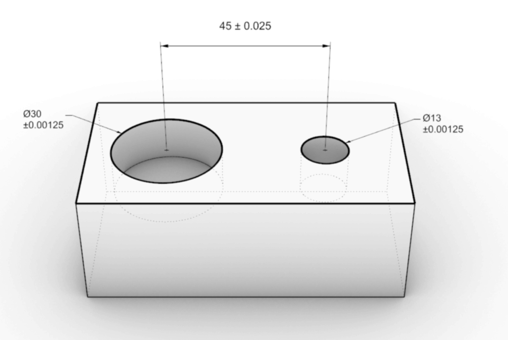
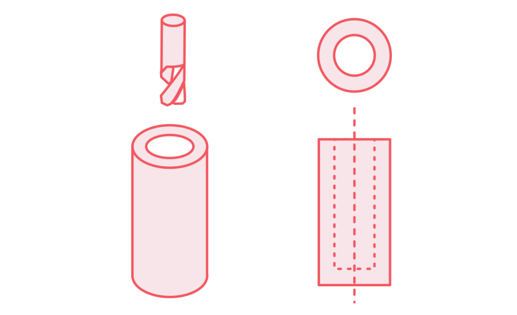
Holes
Keep hole diameter aligned with a standard drill bit set. Clearance holes under 13 mm and coarse thread size taps down to M3 run best. Deeper bores become blind holes, and chip ejection grows tricky, so mind the 3:1 depth‑to‑diameter guideline unless you budget for special tools or peck cycles.
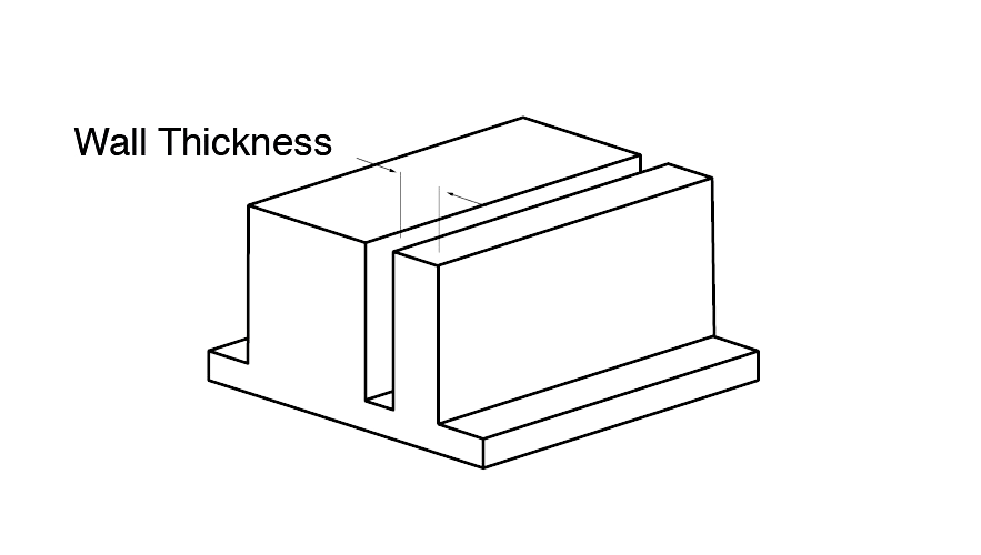
Wall Thickness
Thin walls vibrate, bend, and heat‑soak. A minimum wall thickness of 1 mm in aluminum or 1.5 mm in titanium or steel keeps the workpiece stiff against cutter deflection. Pair vertical walls with supporting ribs or gentle fillets instead of leaving them free‑standing.
Deep Features
Slots, pockets, and other deep cavities require long‑reach tools. Limit cavity depth to four times tool diameter when you can. If an optic or fluid path truly needs a deeper recess, split the part or plan for secondary finishing, such as anodizing, after rough hog‑out.
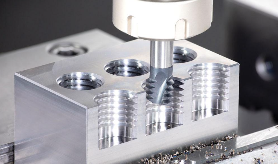
Threads and Inserts
Roll‑formed or cut threads inside threaded holes work fine up to about 3× diameter depth. Any deeper and tap breakage looms. Metal‑shell or helical inserts help when you must blend soft alloys with hard bolts or when repeated assembly would strip the parent metal.
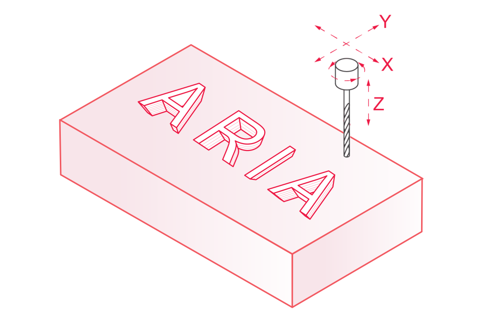
Text
Raised or recessed characters add branding or orientation marks. Set stroke width above cutter tip size and include a gentle flat at the base so the smallest end mill can clear chips.
Radii
Never leave sharp corners inside a slot. Add internal corner radii at least equal to the chosen tool diameter—bigger is better for strength and faster feeds. Outside edges can keep a crisp look, but even a tiny 0.25 mm chamfer knocks off sharp edges that slice fingers.
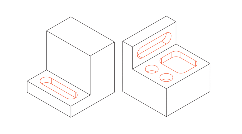
Cavities and Pockets
Wide‑open pockets carve faster with larger mill tools. Break massive voids into stepped levels so each pass removes a steady amount of material instead of burying the flutes. This move shortens cycle time and preserves the surface finish at the base.
CNC Machining Design Guide for the Milling Process
Milling shapes most CNC‑machined parts—from gearbox covers to surgical fixtures. A basic three‑axis mill rewards smart geometry and straightforward choices.
Pick standard cutter
Reach for common flat or bull‑nose end mills. Exotic profiles slow delivery, raise costs, and make resharpening a headache.
Smooth the corners
Swap sharp internal angles for gentle fillets. The tool stays in motion, feeds stay high, and chatter stays low.
Shallow the slots
Deep, skinny cuts invite vibration and part flex. If the slot must go deep, open one side or choose a T‑shape: a big cutter roughs the bulk, a slimmer one cleans the walls.
Go big on radii
Large internal arcs let you crank up feed rate, ease spindle load, and leave a cleaner surface finish.
CNC Turning Design Tips
In turning, the stock spins and the cutting insert stays put. You get round, accurate features fast—if you avoid a few common pitfalls.
Add a radius to internal grooves. A sharp corner makes the insert stall and weakens the part. A small relief groove keeps the cut smooth and reduces stress.
Keep slender shafts under control. Long, thin parts whip at speed. Support them with a tailstock, or break the design into two shorter pieces that thread or press together.
Build walls with enough thickness. Anything thinner than about 1 mm flexes under the tool, spoiling tolerance and finish. Add material or ribs to stiffen the section.
CNC Machining Design Guide for the Drilling Process
Drilled holes look easy, but a few missteps can wreck a part. Use these quick checks to stay safe and accurate:
Keep holes whole
Don’t leave half‑circles hanging off an edge. They make drills skid and leave rough edges. Shift the hole inward or mill the shape instead.
Stay square
Point the drill straight at the surface. A tilted start drags the tip sideways and snaps small bits. Spot‑drill first or machine a flat landing pad.
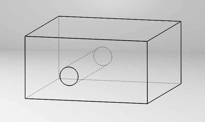
Skip hidden voids
Drilling into an open cavity traps chips and can crack the far wall. Drill the hole before pocketing, or reroute it.
Stick to standard sizes
Metric and inch charts cover the common diameters. Odd sizes need reamers and cost extra.
Limit thread depth. Deep taps seize and snap. Aim for threads 1.5–2 times the hole diameter unless testing proves you need more.
Beyond Subtractive: When to Pivot
Sometimes 3D printing, sheet metal, or injection molding beats machining for large production runs or complex undercuts that the mill can’t reach. Still, design for manufacturability starts with the same mindset: reduce setups, favor standard cutters, and place datums so inspection happens quickly.
Final Design Tips and Cost Control
Keep stock shapes close to the final part size to shave material selection waste.
Request anodize, nickel plate, or paint only where needed; each extra finish adds queue time.
Supply a clean CAD file and mark only the faces needing tolerances beyond ±0.13 mm.
Call out undercuts only if absolutely essential. Many go away with a small fillet or re‑angled wall.
Ask for a design guide review from the vendor before release; small edits often slash machining time and total price.
Follow these steps and your next batch of metal parts—from simple brackets to complex aerospace housings—will leave the mill on time, on spec, and within budget.
Frequently Asked Questions (FAQs)
Q: What’s the difference between a general machining process and the CNC machining process?
A: A traditional machining process often relies on manual controls, gauges, and the operator’s feel to guide cutters and remove metal. The CNC machining process hands that job to computer code.
Once the program runs, the machine follows it line‑by‑line, making each cut in the same spot every time. You gain repeatable material removal rates, tighter feature alignment, and faster changeovers because the recipe lives in the G‑code, not in one operator’s muscle memory.
Q: How should I design parts so the cutting tool can reach every surface?
A: Start by picturing a pencil trying to trace each pocket. That mental check points out spots with poor tool access. Keep walls low, add generous corner radii, and avoid buried internal edges that trap chips. When you design parts with these rules, you save machining passes and reduce the odds of chatter marks hiding in deep corners.
Q: When does CNC turning make more sense than milling?
A: Choose CNC turning when most of your features are concentric around a central axis—think shafts, bushings, or threaded rods. The spinning chuck removes stock evenly, giving roundness in microns while using a single setup.
It is often the most cost‑effective route for cylindrical work because one tool face can tackle multiple diameters, grooves, and even light tapers without repositioning the part.
Q: Why do internal edges affect both cycle time and price?
A: Every abrupt corner forces the programmer to slow the feed or swap to a smaller cutter. Extra tools change stretch cycle time, long reach forms risk vibration, and microscopic re‑cuts can dull the tip early. Softening those internal edges with small radii lets the tool sweep through in one motion, trimming run hours and keeping the quote lean.
Q: How can I keep my next machining project cost‑effective without losing accuracy?
A: Stay inside standard drill and end‑mill diameters, limit surface‑finish callouts to only what the function needs, and group features so a single setup covers them all. These choices cut idle moves, slash unnecessary passes, and reduce scrap—all big drivers of cost. Good design keeps material removal efficient, maintains clear tool access, and avoids over‑specifying details that machinery already holds by default.