CNC Machining Tolerance: Types and Explained

Home >  Blog >

CNC Machining Tolerance: Types and Explained

Machining processes have evolved significantly in the recent past. However, despite the advancements, one aspect remains constant: There is no perfect machining. Regardless of the chosen manufacturing process, there is always a slight difference between the measurements indicated in a CAD model and the actual dimensions of the manufactured part.

In fact, if you were to use the same machining process and CNC machine to try and create two identical parts, there would be some differences between those parts.

So, how can manufacturers ensure consistency in the production of consumer goods? This is where CNC machining tolerances come in.

In this article, I’ll walk you through the essentials of CNC machining tolerances. Read on to learn more about the concept of machining tolerances, how they are measured and calculated, and the different types of CNC machining tolerances.

What is Machining Tolerance?

CNC Machining Tolerance

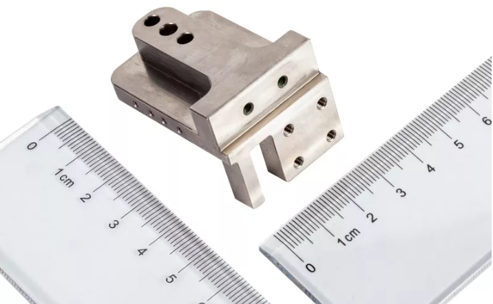
Machining tolerance, also known as dimensional accuracy, refers to the maximum permissible deviation between the blueprint measurements and the final dimensions. It is usually indicated by a number preceded by a ±symbol.

For example, if a part with a blueprint length of 10 mm is assigned a tolerance of ±0.05 mm, the final measurements can lie between 9.95 mm and 10.05 mm. Any value within this range would pass quality inspection.

CNC machining is known for its extreme precision and capacity to achieve tight tolerances. However, high levels of accuracy, signified by smaller or tighter tolerances, will significantly increase machining costs and production time. Since different components call for different levels of precision, it’s more cost-efficient to assign a specific CNC machining tolerance based on part requirements.

This way, machinists can vary between looser tolerances or tight tolerances as needed.

Calculation and Expression of Machining Tolerances

Before I get into the actual calculation of machining tolerances, I’ll take you through commonly used terms that you need to be familiar with.

  • Nominal value or Basic size – This is the measurement that is provided on the CAD drawing. This value is theoretical since designers know the final measurements will vary slightly.

  • Actual size – As the name suggests, this is the final dimension of the manufactured part. The goal of manufacturing processes is to ensure that the actual size and basic size are as close as possible.

  • Upper Limit – This is the maximum permissible dimension of a part. If the size of the part exceeds this value it is no longer usable.

  • Lower limit – Similarly, the lower limit is the minimum permissible dimension of a part. If the actual size is smaller than this value, the part is rejected.

  • Deviation – This is the maximum allowed difference between the measurements of the part and the nominal value. There are 2 types of deviation: upper deviation and lower deviation.

    Upper deviation is a positive value computed as follows;

    Upper deviation = Upper limit – nominal value

    Similarly, lower deviation is a negative value computed as follows;

    Lower deviation = Lower limit – nominal value

Now that we understand the terminology associated with machining tolerances, let’s get into the mathematical bit.

Machining tolerance is the difference between the upper and lower limits of a measurement. With this definition, it becomes incredibly easy to calculate the tolerance of a part.

As an illustration, let’s say a table with a basic length of 100 mm has the following limits:

  • Upper limit – 110 mm
  • Lower limit – 90 mm
  • The tolerance would be the difference between the limit tolerances;
  • Tolerance (t) = upper limit – lower limit
  • t = 110 – 90 = 20 mm
  • In this case, the tolerance band can also be expressed as ±10 mm.

Common Types of Tolerances in CNC Machining

Engineering tolerances are a vital aspect of modern CNC machining. They help manufacturers produce high-quality parts and interchangeable components in the case of mass production.

Now that we’re familiar with the basics of tolerances in CNC machining, I’ll take you through the different types of tolerances.

Geometric Tolerance

CNC Machining Tolerance Detail

Engineering tolerances are a vital aspect of modern CNC machining. They help manufacturers produce high-quality parts and interchangeable components in the case of mass production.

Now that we’re familiar with the basics of tolerances in CNC machining, I’ll take you through the different types of tolerances.

  • General Tolerances

General tolerances, also known as standard machining tolerances, specify typical tolerances for the most commonly machined parts. If an engineering drawing does not provide specific tolerance requirements, machinists will apply standard tolerances.

Standard machining tolerances apply to various components including linear and angular dimensions as well as external radius and chamfers. They are based on international standards and they are usually presented in a chart. For example, ISO 2768 dictates the standards in Europe while ASME’s Y14.5 is used in the US.

  • Unilateral Tolerances

Unilateral tolerance specifies that the permissible deviation can only happen in one direction. This means that there can either be a positive variance or a negative variance but not both.

For instance, a unilateral tolerance of +0.00/ -0.05 mm means that the final dimensions can be smaller than the nominal value by 0.05 mm. However, a bigger part would not be acceptable.

Unilateral tolerances are often used for parts that are fitted into others. If such parts are bigger than is specified, they would not fit into their position.

Let’s say a pipe with a diameter of 20 mm goes into a hole with the same diameter. If the measurements of the pipe exceed 20 mm, that part becomes unusable. In such cases, the allowable variance would be negative.

  • Bilateral Tolerances

Unlike Unilateral tolerance, bilateral tolerance hints that the allowable deviation can be in either direction. In other words, the final dimensions can be slightly bigger or slightly smaller than the specified measurements.

For example, if a part with a diameter of 20 mm has a bilateral tolerance of ±0.05 mm, the upper and lower limits would be 20.05 mm and 19.95 mm. All values within this tolerance range are, therefore, permissible. 19.95 – 20.05 mm is an example of a limit tolerance, with 19.95 being the lower limit and 20.05 being the upper limit.

Bilateral tolerances are typically used for exterior dimensions.

  • GD&T

Geometric dimensioning and tolerancing (GD&T) is more comprehensive than standard machining tolerances. In addition to dimensions and their permissible variances, this system also details further geometric characteristics of a part.

For example, if a bench has a height of 500 mm and an acceptable variance of 20 mm, this implies that a bench with a height of 480 mm on one end and 520 mm on the other would still be permissible. That’s where GD&T comes in. In this case, it would outline that the design intent of the feature is a flat surface.

In addition to flatness, GD&T communicates part characteristics such as straightness, circularity, symmetry, concentricity, position, parallelism, and perpendicularity.

Dimensional Tolerance

Dimensional tolerances establish limits that apply only to the dimensions of a feature. This control applies to measurements only, and it does not define other aspects of a feature such as form, orientation, and profile. Common types of dimensions that may have tolerances include linear, angular, and radial dimensions.

For example, a table may have a height tolerance of ±20 mm, meaning that it would be accepted if it was a bit taller or shorter.

Position Tolerance

Position Tolerance

Position tolerance is the maximum allowed deviation of a feature from its true position. As I have already discussed, manufactured parts cannot match blueprint drawings perfectly. This also stands true for the position of features.

The “true position” is the theoretical position of a feature, and basic or nominal dimensions outline it. Position tolerance defines the limits of your feature’s position from the intended location. It is especially crucial for mating parts as it facilitates smooth assemblies.

Position tolerance is commonly applied for features such as holes, bosses, and keyways.

Angularity Tolerance

Angularity Tolerance

Angularity tolerance controls the orientation of a feature that is at an angle to a datum surface. Note that angularity does not define angle variation between features, for example, ±5degrees.. Rather, it outlines a tolerance zone consisting of two parallel lines that are at the specified angle with respect to the datum. The referenced feature should lie in this zone to be accepted.

Angularity callout is especially useful for parts that mate at an angle. This control is measured using Co-ordinate Measuring Machines (CMMs), angle plates, or surface plates.

Runout Tolerance

Runout Tolerance

Runout tolerance is a type of control that establishes limits for how much a particular feature fluctuates with respect to the datum when the feature is rotated 360 degrees around the datum axis. In other words, runout specifies how much variation can occur when a feature is rotated around a central axis.

Many applications across industries call for rotating parts which makes rotating tolerance quite common. Popular uses include spindles, shafts, drills, gears, and wheels.

Surface Finish Tolerance

surface finish tolerance

Surface finish tolerance maintains control of the allowed variation of a part surface from the nominal surface.

The surface finish of a part is made up of three separate components: waviness, lay, and surface roughness. When machinists talk about “surface finish” they’re typically referring to surface roughness.

It is essential to maintain the intended surface finish limits since this parameter will significantly affect the look, function, and overall quality of the part.

Concentricity Tolerance

Concentricity Tolerance

Concentricity tolerance is a type of location callout. It sets limits on where the midpoints of the referenced feature should lie with respect to a datum axis.

Concentricity is quite complex and hard to achieve during machining. Therefore, simpler CNC machining tolerances such as runout and position are typically used in its place. Concentricity is usually reserved for complicated components such as transmission gear and shafts.

Roundness Tolerance

Roundness Tolerance

Roundness tolerance, also known as circularity tolerance, is a 2-D callout that controls how perfect a circle is. It ensures that a circular cross-section is as close to a true circle as possible.

The circularity tolerance zone consists of 2 theoretically perfect concentric circles. All the points in the nominally round component need to lie within this tolerance band to be accepted.

Circularity is a common control since there are many applications that call for perfectly circular parts. These include bearings and rotating shafts.

Straightness Tolerance

Straightness Tolerance

Straightness tolerance is a 2-D callout that controls the uniformity of part features. It references how straight a feature is regardless of any datums.

Straightness tolerance can either be applied to a surface or an axis. Surface straightness is measured using a height gauge while axis straightness can be measured using a dial gauge or a cylinder gauge.

The straightness callout is commonly used on mating parts that need to have line contact.

Parallelism tolerance

Parallelism tolerance

Parallelism tolerance controls the parallelism of two part features. There are two types of parallelism, surface parallelism and axis parallelism, with the former being the most common.

Two parallel planes that are parallel to the reference surface define the tolerance zone. For the part to pass a quality check, all the points on the surface need to be within the tolerance zone.

Parallelism tolerance comes in handy when there needs to be a uniform separation between two parts that are in sync. Further, this control ensures that features such as cylindrical holes do not taper.

Modern CMM machines have made it pretty easy to measure parallelism. In the absence of these gadgets, you can determine parallelism using a height gauge or surface plate.

Flatness tolerance

Flatness tolerance

Flatness is a requirement of many CNC machined parts. While no surface can be perfectly flat, machinists can manufacture a surface that is flat enough for its intended application.

Flatness tolerance controls the flatness of a surface. It defines the tolerance zone, which consists of two parallel planes one on each side of the flat surface. If all points of the surface in question lie within the tolerance zone, the part is within the acceptable range.

We use flatness to ensure that two surfaces can mate flush with each other if orientation isn’t as crucial. This property is also essential when you want to maintain an even amount of wear on a surface.

A good example of the flatness callout is with vernier calipers. This instrument uses a fixed and sliding jaw to take measurements. If these two surfaces are not flat enough, the movable jaw would get stuck during movement.

Flatness measurement tools include CMM machines, 3D scanners, and dial gauges.

Perpendicularity tolerance

Perpendicularity tolerance

Perpendicularity tolerance is a type of orientation control that defines the boundaries of where a feature should lie to be considered adequately perpendicular. There are two types of perpendicularity: surface and axis perpendicularity.

As the name suggests, surface perpendicularity is applied to a surface that is oriented at an angle of 90 degrees from a datum. Axis perpendicularity controls the variation of an axis from a perfect 90 degree angle.

Perpendicularity tolerance is commonly applied on the middle axis of a hole.

Author

Gavin Leo is a technical writer at Aria with 8 years of experience in Engineering, He proficient in machining characteristics and surface finish process of various materials. and participated in the development of more than 100complex injection molding and CNC machining projects. He is passionate about sharing his knowledge and experience.