Fillet vs Chamfer: Basic Operations & Cad Design Features 2022

Fillet-vs-Chamfer

A chamfer is nothing more than an element of a part. The word chamfer owes its origin to the French word “ faccete ”, which means the beveled parts of corners, shape  edges, etc. The main part of the chamfers is designed to dull sharp corners in order to ensure the safety of subsequent technological operations or the operation of products and mechanisms.

The CNC chamfering machine is a small-sized continuous automatic programmable metalworking machine for finishing workpieces. The chamfer quickly and efficiently removes the remnants of welding deposits, primary corrosion deposits, burrs, etc., both from the end parts and from the surface of tubular blanks / bushings. 

What is CNC Chamfering machine?

CNC chamfering machine

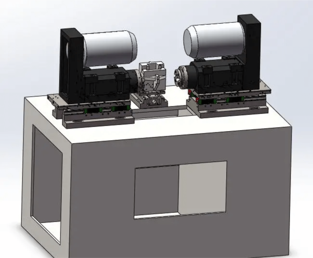
The CNC chamfering machine is assembled on a solid base frame. The workpieces are fed automatically along an inclined path with adjustable width. The pusher, installed at an angle, feeds the sleeve to the fixation. This is done by two shafts with tapered ends to easily fit into the hub. The shaft diameters are the same and are selected based on the bushing section. 

The first shaft is fixed and rotates in the stationary headstock chuck; it receives torque from a high-speed electric motor. The second shaft is held in the cartridge of the longitudinally movable headstock, and it is he who presses the sleeve against the first shaft.

 This shaft is not driven, but a reliable and durable bearing is installed in the chuck, therefore, after clamping, both shafts rotate, firmly holding the workpiece at high speeds. As soon as the sleeve is fixed, a cutter is automatically fed to it, fixed in a tool holder moved by a movable caliper. The cutter is fastened with two bolts, it can be easily replaced; a set of cutters is available as an option. 
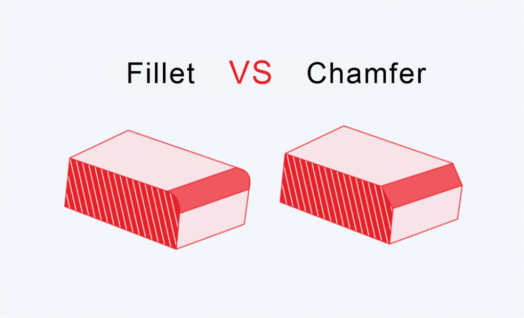
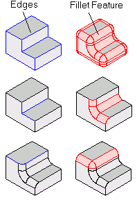
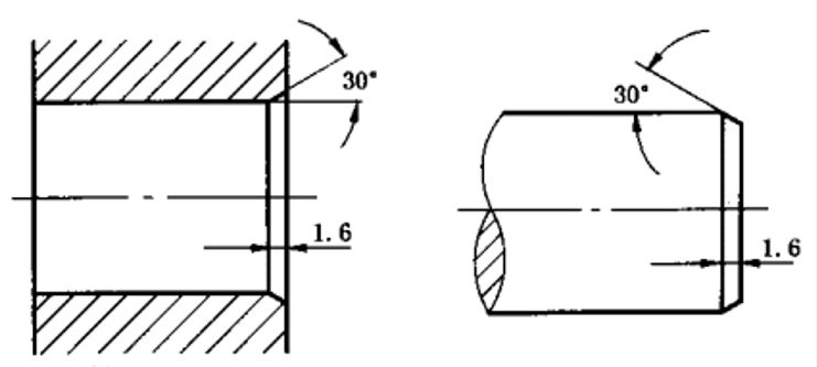
The support, according to a given program, starts the cutter feed from one end cut, guides the cutter along the workpiece, and ends with the second end cut. Thus, a chamfer is removed from two ends and along the entire length of the workpiece. Once this is done, the movable headstock releases the clamp and the workpiece falls down into the build pan. 

Function of CNC beveler

The CNC beveler is equipped for process control with a mobile operating unit with a touch screen, in the field of which all program parameters are entered. The intuitive interface allows you to quickly master the control procedure. Among the controls, there is also an emergency power off button.

Types of Fillet

Types of Fillet

The fillet command is FILLET, and the fillet function connects two objects using an arc that is tangent to the object and has a specified radius. There are two types of fillets that can be created, the inner corner point is called a fillet, and the outer corner point is called a fillet.

Objects that can be rounded include arcs, circles, ellipses, elliptical arcs, lines, polylines, construction lines, and 3D objects. The chamfer command generates a bevel at the line connection. You can set the size of the bevel by setting the distance and angle. Other operations and techniques are basically the same as the fillet. Therefore, the rounded corner command will be used to introduce some common techniques for both.

1. Basic operations to rounded corners

①.We can draw any graphics to carry out the following exercises, but we must know the size of the graphics in advance so that a reasonable corner radius can be set. Draw a rectangle of size 200X150 as shown in the image below.

②. Enter F, press the space bar or Enter (the latter are abbreviated as Enter), execute the fillet command, enter R, enter, and enter 50 as the fillet radius.

③. Press Enter, and when prompted to select the first and second objects, click the two adjacent sides of the rectangle to create rounded corners.

④. Press Enter, repeat the command, and directly select the other two adjacent sides of the rectangle to create a new rounded corner.

⑤. After we set the fillet radius, this radius will be used by default next time, and there is no need to repeat the setting, so fillets with the same radius can be created continuously until other radii need to be set. The final set corner radius will be saved with the drawing, which means that the next time we open this drawing; we can continue to use the previously set corner radius.

2. Modify and delete rounded corners

After creating a fillet, if you need to modify the fillet radius or delete the fillet, you only need to reset the radius to another value or 0, and then select the two sides of the fillet to complete the modification and deletion of the fillet. . Enter F , enter, enter R , enter, enter 20 , enter, select the two edges that have been rounded, and change the radius of 50 to the radius of 20 .

3. Create multiple rounded corners at one time on a polyline

①. If all corners of a continuous polyline need to create rounded corners with the same radius, we do not need to click again and again to select adjacent line segments. We can use the rounded polyline option. In order to better observe the effect of polyline rounding. We can draw a more complex polyline, with long and short line segments.

②. Enter F , enter, enter R , enter, enter 50, enter, enter P , enter, the command line will prompt to select polyline, click the drawn polyline, all rounded corners will be generated at one time

③. When the length of the line segment is less than the radius of the fillet, the fillet cannot be generated. The command line will tell us the number of fillets generated and the number of ungenerated fillets.

4.Trim and extend graphics with rounded corners

When two lines cross or do not intersect, we can use the fillet command when we want to connect the two lines together and trim off the excess. Draw four straight lines as shown in the image below.

5. Three-dimensional solid rounding

The fillet command can not only chamfer two-dimensional lines, but also chamfer three-dimensional solids. When selecting the edge that needs to be chamfered on the 3D solid, you will be prompted to input the fillet radius. After entering the radius, you can select one or more edges to fillet at the same time.

6. To parallel lines to rounded corners

We can not only round the intersecting lines, but also round the parallel lines. The parallel lines will be automatically connected with a semicircle without setting the chamfer radius.

7. Pruning

We can see that the rounded corner has a trimming parameter T. By default, the selected edit will be trimmed or extended when the rounded corner is generated, but if there are special needs, it can be set to not be trimmed to generate a circle corners but keep the original lines, as shown in the image below.

8. Reverse fillet

In the later versions of cad, a reverse I parameter has been added to the fillet, which can be used to create some architectural or interior design. The reverse fillet is often used, if you are interested you can try.

On technical drawings, chamfers and their geometric parameters are indicated in cases where it is necessary to explicitly indicate its presence, due to the technical solution. In other cases, chamfers, or what other forms of edges are not indicated, but must be blunted during the manufacturing process.

Mostly, as mentioned above, chamfers are designed to ensure safety during further interaction between a person and the products of his production activity, but in some cases they are needed as decorative elements introduced by designers into the composition of the product.

Most Common Applications of Chamfers

fillet vs chamfer

Chamfers are very commonly used in the woodworking industry. The presence of chamfers here, combined with roundings that turn into fillets and back, are very well combined with flat surfaces and give the product a finished look.

Even the presence of a simple chamfer on any part visually gives it volume, not to mention curly chamfers with varying plunging trajectories and angles of inclination.

When finishing mirrors, decorative chamfers are made along the edges, in the form of small bevels of the edges of the edges.

This kind of facets is obtained by grinding with a special diamond tool, on machines designed for such types of work, with abundant cooling. Edges processed in this way are called “facet”.

 In the manufacture of doors, or any other parts of the interior, glazing elements are used, in the form of small tiles of a given size with a facet. In combination with noble wood, they form a composition that gives a special solemn look and an atmosphere of comfort.

Chamfer With Gentle Bevel

There are chamfers with a shape  edges, which allow parts to perform functions that ensure guaranteed entry or engagement with the mating components of assemblies and mechanisms.  

In internal combustion engines, gas distribution is an important determining part of the operation of the system as a whole. In order to realize the gas exchange conditions, the inlet and outlet openings must open and close in a strictly defined order and ensure efficient gas exchange.

Timely supply of a combustible mixture and the release of exhaust gases are carried out by valves, which are driven by kinematic elements of the mechanisms. One of the components of the valve is the sealing chamfer; it is entrusted with the important function of guaranteed shut-off and ensuring unhindered release of gases.

Heat treatment to Prepare Edges

Building mates

With mate, you can connect two objects using an arc that is tangent to the objects and that has a certain radius.

An inside corner is called a fillet, and an outside corner is called a rounding; you can create both corners using the FILLET command.

You can pair the following objects:

  • Ellipses and elliptical arcs
  • Segments
  • Polylines
  • Splines

You can fillet all corners of a polyline using the FILLET command.

NOTE. The conjugation of hatch boundaries, which consists of segments, leads to a loss of associativity. If the hatch boundary is specified by a polyline, the associativity is preserved.

If both connected objects lie on the same layer, the fillet arc is also drawn on the same layer. Otherwise, it is built on the current layer. The layer defines other properties of the object, including color and linetype.

Using the “Multiple” option, you can pair several objects without leaving the command.

Fillet radius setting

The fillet radius is the radius of the arc connecting the mating objects. Changing the radius affects only the mates performed after this, leaving the existing ones unchanged. If the radius is set to 0, then the mating objects are simply cut off or extended to the intersection point without drawing a mating arc.

Trimming and extending mating objects

With the “Cut” option, you can select a mating mode in which objects are either trimmed / extended to the point of intersection with the mating arc, or remain unchanged.

Specifying junction points

There may be several possible mates, and the program chooses them based on the position of the pick points. Compare the location of the sets of objects and the resulting mates in the drawings.

Pairing lines with polylines

To mate lines with polylines, each line or line extension must intersect one of the line segments of the polyline. When Clipped is on, mated entities and the mating arc are merged to form a new polyline.

Fillet along the entire polyline

You can build or unbuild mates along the entire polyline.

When the fillet radius is non-zero, the FILLET command draws mating arcs at each of the vertices formed by the intersection of linear segments, if these segments are long enough for the fillet radius.

If two converging polyline line segments are separated by an arc, the FILLET command replaces that arc with a fillet arc.

If the fillet radius is 0, then mating arcs are not drawn. If two polyline line segments are separated by a single arc segment, the FILLET command removes the arc and extends the line segments until they intersect.

Conjugation of parallel lines

It is possible to pair parallel segments, lines and rays. The current fillet radius is temporarily adjusted to create an arc that is tangent to both objects and placed on a plane common to both objects.

The first object selected must be a line or ray, and the second must be a line, line, or ray. The mating arc is drawn as shown in the drawing.

Fillet objects with non-zero height in 3D space

fillet

In AutoCAD, you can mate any objects that are in the same plane and have extrusion directions that are not parallel to the Z-axis of the current UCS. The FILLET command defines the extrusion direction for the fillet arc in 3D space close to the direction of the Z-axis of the current UCS.

Summary: Difference between a Fillet and Chamfer

① The above briefly introduces various operation skills and application scenarios of rounded corners. We can see that the rounded corner command can be applied not only to two-dimensional graphics, but also to three-dimensional graphics. It can not only complete its own essential work: rounding corners, which can also be used to trim and extend graphics.

② The chamfering command is similar, except that the setting of the radius is changed to the setting of the distance and the angle. The chamfering can be set to two distances, or one distance and one angle, and the operation is relatively complicated. Of course, there are some differences in the application scenarios of the chamfer command. For example, the chamfer cannot be used on parallel lines.

③ In-depth understanding of each parameter option and possible application scenarios of a command is very helpful for improving drawing efficiency.

Author

Gavin Leo is a technical writer at Aria with 8 years of experience in Engineering, He proficient in machining characteristics and surface finish process of various materials. and participated in the development of more than 100complex injection molding and CNC machining projects. He is passionate about sharing his knowledge and experience.