In the dynamic world of custom plastic part manufacturing, injection molding reigns supreme as a highly efficient and versatile production method. However, one particular aspect that demands meticulous attention and expertise is the management of undercuts.
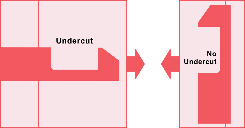
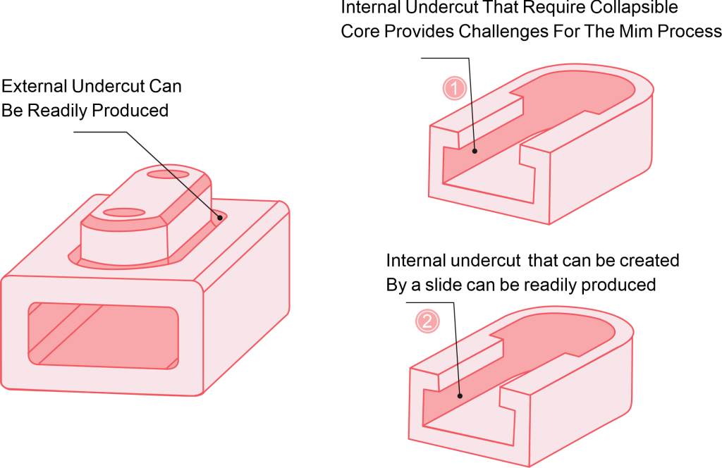
Undercuts, in the context of injection molding, are geometric features within a plastic part that impede its straightforward ejection from the mold. They can take various forms, such as internal cavities, protrusions, or recesses that jut out or indent in a way that obstructs the part’s linear removal from the mold cavity.
Understanding Undercuts in Injection Molding
Undercuts are elements such as hooks and grooves on a plastic part that directly affect how that part functions. These elements can be on the internal and/or external surfaces of a molded part, preventing it from being easily released from a two-part mold. Some of the most common scenarios where undercuts are used include:
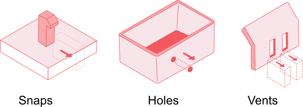
Interlocking undercut features such as latches, tabs, or snaps that replace the need for extra fasteners. They allow easy assembly and convenient function of the end product
Side holes for common items such as electronics and accessories where ports, buttons and other access points can be added to the housing unit
Barb fittings and connectors which create a seal between a fitting and a tube for controlled airflow. These are mostly used when making parts for medical devices
Threads on plastic parts used for fastening. These can be used in hoses, connectors, and other plastic parts to ensure that a connection is secure and can bear a light load
Manufacturing custom plastic parts with undercut features is often complex, and particular care in design is needed to ensure that the molding and release process is easy and fast. In order to retain the parts functionality while avoiding the complexities and extra costs of manufacturing, innovative design and tooling mechanisms are necessary.
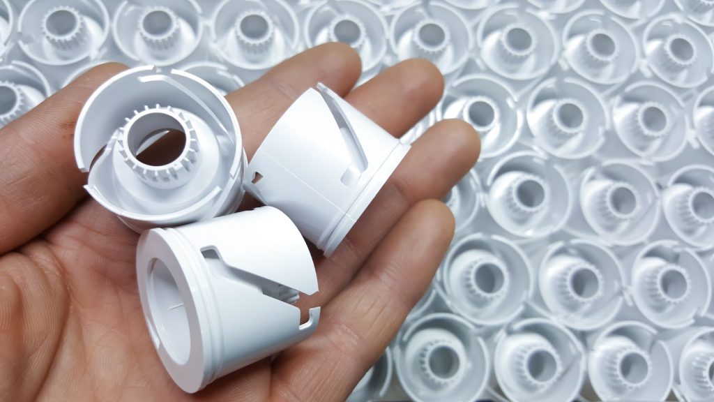
Common Applications of Plastic Injection Molding
Undercuts enhance the aesthetic, functionality and usability of our everyday products. They are especially useful in the following fields;
Consumer electronics such as plastic housings and cases. The undercuts ensure that these products grant the user access to buttons and ports
Medical devices come with some of the most complex parts with intricate designs. Some of these parts could be used in life saving devices such as oxygen delivery, which demands precision in manufacturing so as to not compromise the device’s performance
The automotive industry requires multiple parts with intricate geometrical requirements. Additionally, it requires complex shapes in forms of seals and gaskets for engines and other car components
The packaging industry incorporates undercuts to make the products easy to use, appealing, and functional
It is essential for engineers and designers to collaborate on the mold and part designs when making any of these products to create working solutions. This is especially crucial when coming up with the right techniques for a successful job.
6 Ways to Create Successful Undercuts in Molded Parts
There is a variety of techniques that can be used to efficiently manufacture injection molded custom parts with complex undercuts. The technique employed will, however, depend on the design of the part, the materials needed, and the production volumes. The most common methods used in efficient undercut molding include the following.
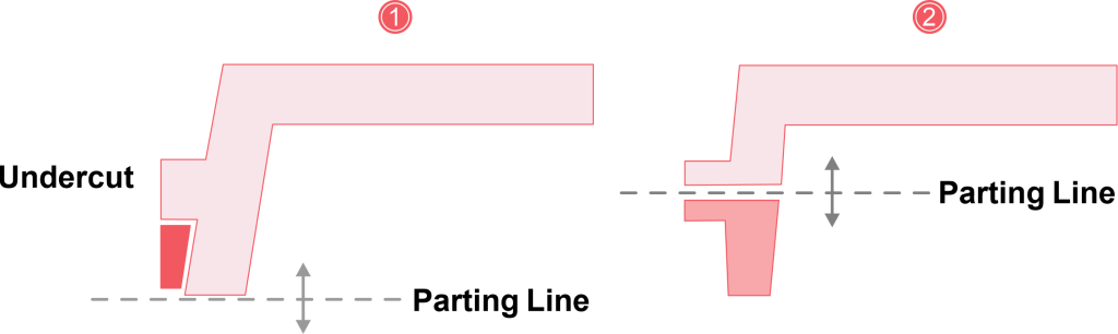
Parting Lines
A parting line is a point where two pieces of a mold separate or split to release the custom part. Depending on the geometry wall thickness of the part and the material flow, this split line can be aligned with the undercut for easy release. Careful design is needed, however, to ensure that the parts are not scraped during release. Sometimes a taper or draft is necessary to ensure that the release process does not interfere with the appearance or functionality the part made with plastic injection molding.
This technique simplifies the manufacturing process by ensuring that there is natural separation following the geometry of the part geometry. It reduces the tooling and maintenance costs and requirements of manufacturing custom parts.
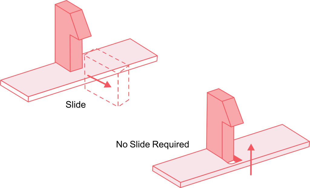
Side Actions
A side action core is a mold design insert where the undercut sits until it slides out during release. Side action employs mechanical components that moves to release the part from this core before the mold opens up to the ejector plate of the part. The mechanism employed can be driven by either springs, cams or hydraulic action. It is a highly precise technique and can be successfully employed for complex designs. It can be used to make high volume parts with external holes, slots, tabs.
For this technique to be effective, the side action core should be perpendicular to the part. Additionally, the materials used should be rigid – this technique requires materials that don’t stick to the mold such as PC, nylon and acetol. It is not the best technique when making flexible parts or items that can deform easily. This technique also requires complex injection molding generally increase part design, and regular maintenance especially when dealing with high production volumes.
Bumpoffs
The bumpoff process is a lot like the normal plastic injection molding except that it has one single insert added to it. When the molding job is complete, the insert is removed first to create space for the molded part to be released. Normally, when the insert is removed, the part deforms slightly due to the hollow created by the insert. This slight deformation allows the molded part with an undercut to be released easily. It is a common technique when using flexible and elastic materials such as LDPE (low density polyethylene), TPU (thermoplastic polyurethane), TPE (thermoplastic elastomer) and LSR (liquid silicone rubber). The bump offs LSR is especially common with gaskets, seals and other highly flexible parts with complex geometries.
While bumpoffs sound simple enough, it is important to ensure that the part can be deformed enough to be released without damaging its shape or functionality. This technique should not be used on stiffening features such as ribs and corners. It is important to keep the lead angle between 300 and 400.
Bumpoff technique is suitable for a range of applications that require small and simple internal undercuts, such as tabs or hooks. It is a cost-effective solution for jobs with low to moderate complexity.
Hand-Loaded Inserts
As the name suggests, this is a technique that requires manually placing metal pieces into molds to prevent flow of material to unwanted parts of the mold. The process is similar to side actions, except that this is not automatic but rather done manually by technicians. This is generally used to create the option for intricate undercut molding designs that require precision but the costs of production are too high to automate the process
Being a manual process, hand loaded injection molding jobs take time to complete and may not work well for high volume productions. Additionally, the technique creates safety concerns for workers, even with safety gear.
Shutoffs
Sliding or telescopic shutoffs are temporary obstructions that are placed on the mold to prevent flow of the material to unwanted parts of the design. These obstructions can use clips, hooks, or any other snap-fit components. The shutoffs can be used in place of hand loaded inserts or side actions as they are more cost effective and faster. However, the mold needs to be effectively modified for best results.
Depending on the design of the parts being manufactured, it is important to have enough draft angles. This is to ensure that the molded parts are ejected smoothly. Additionally, the vertical threads or top side must have a minimum of 3 degrees difference. This is to ensure the safety of the undercut design and prevent rubbing or damage to the tool.
Secondary Operations
Secondary operations refer to a variety of processes that are used to add features to a part after molding. These processes can be carried out away from the molding machine and therefore may not require any changes to the mold. For instance, in order to create a hole, the part can be put in a drill press or milling machine after molding. These operations can also include assembling additional parts post-molding.
This technique is particularly useful in operations where mold modification is not preferred or possible. While it allows for greater flexibility when dealing with part design modification, it adds to the production time and costs. It also reduces efficiency when dealing with largescale productions.
Design Considerations for Undercut Features Molding
Designing for undercuts is a complex process that requires a deep understanding of the materials to be used and how they behave, the mechanics of the molds and the production constraints. To improve the efficiency of the design process interior undercuts, have the following in mind:
Choose materials with the appropriate flexibility for the process you will use e.g. for bumpoffs and the thermal properties e.g. for secondary operations
Maintain tight tolerances in critical features to ensure proper function and assembly especially if multiple components are involved. Tolerance stack-up analysis can help identify potential assembly issues early on in the design process
Incorporate adequate draft angles to make part ejection easy and smooth. Consider the required surface finish when choosing draft angles – larger draft angles are best for parts that need aesthetic high-gloss or textured finishes
Iterative prototyping is an essential part of product design, especially when dealing with complex designs. You can use mold flow analysis tools to simulate production and predict potential challenges so that you can refine the process and designs before production
Choosing The Right Technique for Undercut Injection Molding
There are a few considerations to have in mind when considering the best technique for the undercuts of the parts you want to make with injection molding. These factors include:
The location and complexity of the undercuts – simple designs can use the mold’s parting lines or side actions
The flexibility of the materials being used – bumpoffs are best for flexible materials while secondary operations are best for rigid materials
The production volume – high volume productions justify the costs of acquiring an automated system while low volumes can work with secondary operations
The time and cost constraints for long term projects especially when upfront tooling costs are needed
Design requirements – for example, side actions must not be too tightly placed when in production to reduce the risk of them getting stuck. Hand-loaded inserts must be easily and safely accessible to the operator.
Conclusion
Undercuts have been a challenge in plastic injection molding. However, with the right designs and tooling techniques, they play a vital role in the functionality and aesthetics of molded parts. By leveraging methods such as optimized parting lines, side-actions, bumpoffs, hand-loaded inserts, and secondary operations, manufacturers can produce high-quality injection molded parts that meet both functional and aesthetic requirements.
An understanding of the trade offs between cost, complexity and scalability of plastic material is crucial when picking the right plastic injection molding technique. Whether the project is solely for prototyping or mass production, proper planning ensures that the project is completed efficiently and successfully. By implementing various solutions, engineers and designers can experiment with endless possibilities of custom plastic parts manufacturing.