


A drawing calls for a 60 mm wide slot. The machined part arrives, and the slot measures 60.2 mm. Is it acceptable?
That depends on how far a finished part may stray from the drawing. Tolerance limits set that range. Without them, the machinist has to guess.
Writing an individual tolerance on every dimension fixes this, but it buries the technical drawing in numbers. General tolerances handle it with one note in the title block. On the many drawings that still say general tolerances ISO 2768-m (1989 edition), every size without its own tolerance inherits a default based on its size. The 60 mm slot gets ±0.3 mm, so 60.2 mm passes the slot-width requirement. (That says nothing about the rest of the part, which has its own requirements.)
This guide explains how ISO 2768 general tolerances work in CNC machining, how to read the 1989 tables you will meet on existing drawings, how to apply general tolerances, and how to choose a standard for new drawings now that the standard has changed.
- Edition note: ISO 2768-1:1989 has been replaced by ISO 2768:2026, published on 9 November 2026. ISO 2768-2:1989 was withdrawn in 2021 and replaced by ISO 22081:2021. The tables and worked examples in this article come from the 1989 editions. Use them to read the many drawings that still cite ISO 2768-m or ISO 2768-mK.*

What Is ISO 2768 ?
ISO 2768 is the international standard family for general tolerances in manufacturing. General tolerances are default tolerances for dimensions and geometry that have no tolerance written next to them. Because an international committee maintains this international standard, a machinist in one country and a buyer in another read the same note the same way. For CNC machining projects that cross borders, this removes a common source of disputes.
It also gives mechanical engineering teams, buyers and inspectors one shared reference for what is acceptable. Manufacturers get clear acceptance criteria, and inspectors can check parts against the same limits.
The family has changed over time, so the edition matters:
| Document | What it covers | Status on November 12, 2026 |
|---|---|---|
| ISO 2768-1:1989 | General tolerances for linear and angular dimensions. Four tolerance classes: f (fine), m (medium), c (coarse), v (very coarse). | Withdrawn. Replaced by ISO 2768:2026. |
| ISO 2768-2:1989 | General geometrical tolerances. Three classes: H, K, L. | Withdrawn in 2021. Replaced by ISO 22081:2021. |
| ISO 2768:2026 (Edition 2) | Tolerance limits for general specification of linear and angular sizes. | Published 9 November 2026. |
| ISO 22081:2021 | Rules for defining and interpreting general geometrical specifications and general size specifications. | Current. Reviewed and confirmed in 2026. |
A legacy print combines both 1989 parts in one designation. ISO 2768-mK means class m from Part 1 and class K from Part 2. Each letter is part of the tolerance class designation. Some prints write it without the space, as ISO2768-mK. Both mean the same thing. If a print gives no year, confirm which edition governs the order before you quote or machine the part.
General tolerances apply only within the scope of the standard cited, and only where a feature has no individual tolerance for that characteristic. A critical feature, such as a mating bore, still needs its own tolerance indication. Under the 1989 Part 1, these are also outside general tolerances:
- auxiliary (reference) dimensions shown in parentheses,
- theoretically exact dimensions shown in boxes, and
- dimensions covered by another general tolerance standard.
ISO 2768 – 1:Linear and Angular Dimensions
The 1989 Part 1 keeps prints simple. It gives tolerances for linear and angular dimensions, and it covers external sizes, internal sizes, step sizes, diameters, radii and distances, plus external radii and chamfer heights on broken edges. Tolerances come from three tables. Part 1 defines four tolerance classes, and each one matches the normal accuracy of common machining processes. Pick the tolerance class your manufacturer can hold without extra effort.
For Tables 1.1 and 1.2, nominal dimensions below 0.5 mm require individually indicated deviations. This lower limit does not apply to the side-length ranges used to select angular tolerances in Table 1.3. Second, a dash (–) means the standard gives no value for that cell. It is not zero tolerance, and you must not borrow a value from the neighboring row or column.
Table 1.1 Linear Dimensions
| Permissible deviations in mm | ||||
|---|---|---|---|---|
| Basic size range in mm | f\ (fine) | m\ (medium) | c\ (coarse) | v\ (very coarse) |
| 0.5 up to 3 | ±0.05 | ±0.1 | ±0.2 | – |
| over 3 up to 6 | ±0.05 | ±0.1 | ±0.3 | ±0.5 |
| over 6 up to 30 | ±0.1 | ±0.2 | ±0.5 | ±1.0 |
| over 30 up to 120 | ±0.15 | ±0.3 | ±0.8 | ±1.5 |
| over 120 up to 400 | ±0.2 | ±0.5 | ±1.2 | ±2.5 |
| over 400 up to 1000 | ±0.3 | ±0.8 | ±2.0 | ±4.0 |
| over 1000 up to 2000 | ±0.5 | ±1.2 | ±3.0 | ±6.0 |
| over 2000 up to 4000 | – | ±2.0 | ±4.0 | ±8.0 |
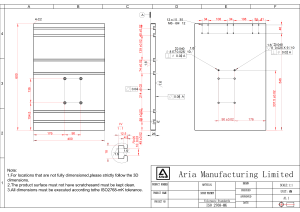
Use this table for tolerances for linear dimensions such as length, width, height, diameters, radii and distances. Pick the row by the nominal size of the feature. Linear dimensions permissible deviations grow as the size ranges grow.
How to read it: Say a step is 18 mm tall and the print calls class m. Go to the row “over 6 up to 30” and the m column. The 18 mm tolerance class m limit is ±0.2 mm, so the step is good from the lower limit of 17.8 mm to the upper limit of 18.2 mm.
Table 1.2 External Radii and Chamfer Heights
| Permissible deviations in mm | ||||
|---|---|---|---|---|
| Basic size range in mm | f\ (fine) | m\ (medium) | c\ (coarse) | v\ (very coarse) |
| 0.5 up to 3 | ±0.2 | ±0.2 | ±0.4 | ±0.4 |
| over 3 up to 6 | ±0.5 | ±0.5 | ±1.0 | ±1.0 |
| over 6 | ±1.0 | ±1.0 | ±2.0 | ±2.0 |
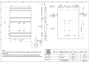
Use this table only for broken edges: the external radii and chamfer heights that remove a sharp edge. Do not apply it to functional arcs or to the radii of a part outline. Those are radii in the ordinary sense and take their tolerance from Table 1.1. Pick the row by the nominal size of the radius or chamfer height. Chamfer heights permissible deviations are the same for classes f and m, and for classes c and v.
How to read it: Say a deburring radius on an edge is 2 mm and the print calls class c. Go to the row “0.5 up to 3” and the c column. The 2 mm tolerance class C limit is ±0.4 mm, so the radius is good from 1.6 mm to 2.4 mm.
Table 1.3 Angular Dimensions
| Permissible deviations in degrees and minutes | ||||
|---|---|---|---|---|
| Basic size range in mm(shorter side of the angle concerned) | f\ (fine) | m\ (medium) | c\ (coarse) | v\ (very coarse) |
| up to 10 | ±1° | ±1° | ±1°30′ | ±3° |
| over 10 up to 50 | ±0°30′ | ±0°30′ | ±1° | ±2° |
| over 50 up to 120 | ±0°20′ | ±0°20′ | ±0°30′ | ±1° |
| over 120 up to 400 | ±0°10′ | ±0°10′ | ±0°15′ | ±0°30′ |
| over 400 | ±0°5′ | ±0°5′ | ±0°10′ | ±0°20′ |
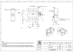
Use this table for angular measurements such as a bevel or a tapered face. The relevant nominal size for an angle is its shorter side, so always pick the row by that side. Angular dimensions permissible deviations shrink as the shorter side gets longer.
How to read it: Say a 45° bevel has a shorter side of 80 mm and the print calls class m. Go to the row “over 50 up to 120” and the m column. The 80 mm tolerance class m limit is ±0°20′, so the angle is good from 44°40′ to 45°20′.
Implied right angles: A 90° angle that the print does not dimension is still an angle. If it cites only Part 1, the general angular tolerance covers it. If it cites Part 2 as well (for example mK), the Part 2 perpendicularity ranges cover it.
ISO 2768 – 2:Geometrical Tolerances for Features
The 1989 Part 2 simplified prints in the same way as Part 1, but for geometry. Part 1 sets size tolerances. Part 2 set form, orientation and position tolerances in three classes: H, K, L. It gave general tolerances for straightness, flatness, perpendicularity, symmetry and circular run-out. These values are still on countless prints, so you need to be able to read them. ISO 22081 replaced Part 2, but it does not simply swap in a new H/K/L table. See “The Current Standards” below.
For a size dimension, the tolerance is the difference between the upper and lower limits. The upper and lower deviations locate those limits relative to the nominal size. For example, ±0.2 mm gives a total size tolerance of 0.4 mm. A geometrical tolerance defines an allowable zone whose shape and relationship to datums depend on the geometrical characteristic.
Table 2.1 Straightness and Flatness Tolerances
| Permissible deviations in mm | |||
|---|---|---|---|
| Ranges of nominal lengths in mm | H | K | L |
| up to 10 | 0.02 | 0.05 | 0.1 |
| over 10 up to 30 | 0.05 | 0.1 | 0.2 |
| over 30 up to 100 | 0.1 | 0.2 | 0.4 |
| over 100 up to 300 | 0.2 | 0.4 | 0.8 |
| over 300 up to 1000 | 0.3 | 0.6 | 1.2 |
| over 1000 up to 3000 | 0.4 | 0.8 | 1.6 |
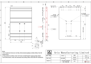
Use this table for the form tolerances of a single feature.
Flatness controls how far a surface may stray from a perfect plane. Pick the row by the longer side of the surface, or by the diameter of a round surface.
Straightness controls how far a line may stray from a straight line. For the general tolerances in this table, pick the row by the length of the relevant line on the surface. Do not assume the table also gives a separate requirement for the straightness of an axis.
Circularity has no table. Its general tolerance equals the total width of the diameter tolerance zone, but never more than the circular radial run-out value in Table 2.4. For a diameter of ±0.1 mm, the zone is 0.2 mm wide, so the circularity tolerance is 0.2 mm, unless the run-out value for the class is smaller.
Table 2.2 Perpendicularity Tolerances
| Permissible deviations in mm | |||
|---|---|---|---|
| Ranges of nominal lengths in mm(shorter side) | H | K | L |
| up to 100 | 0.2 | 0.4 | 0.6 |
| over 100 up to 300 | 0.3 | 0.6 | 1 |
| over 300 up to 1000 | 0.4 | 0.8 | 1.5 |
| over 1000 up to 3000 | 0.5 | 1 | 2 |
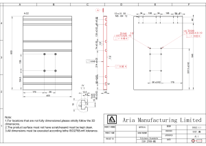
Use this table for the orientation of one feature relative to another at 90°. The longer side of the right angle is the datum. The shorter side picks the row.
Parallelism has no table. Its general tolerance equals the size tolerance or the applicable flatness or straightness tolerance, whichever is greater. Use the total width of the size tolerance. A thickness of ±0.2 mm has a size tolerance of 0.4 mm, and that is the number to compare. The longer feature is the datum.
ISO 2768-2:1989 does not specify a general angularity tolerance. Where a geometrical angularity control is required, specify it individually. This does not prevent an angular dimension from receiving a general angular tolerance under ISO 2768-1:1989
Table 2.3 Symmetry Tolerances
| Permissible deviations in mm | |||
|---|---|---|---|
| Ranges of nominal lengths in mm | H | K | L |
| up to 100 | 0.5 | 0.6 | 0.6 |
| over 100 up to 300 | 0.5 | 0.6 | 1 |
| over 300 up to 1000 | 0.5 | 0.8 | 1.5 |
| over 1000 up to 3000 | 0.5 | 1 | 2 |
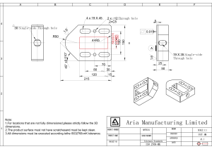
Permissible deviations in mm. Use this table for features that must sit centered on another feature, such as a slot centered on a part. Pick the row from the symmetry ranges by the length of the longer of the two features. That longer feature is the datum. If both are the same length, either may be the datum. The symmetry ranges for class H stay at 0.5 for every length, while classes K and L grow with size.
Table 2.4 Run-out Tolerances
| Permissible deviations in mm | |||
|---|---|---|---|
| Circular Run-out | H | K | L |
| – | 0.1 | 0.2 | 0.5 |
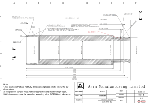
Use this table for run-out tolerances on rotating features.
Circular run-out controls how much a surface varies when the part turns around its axis. It applies to radial, axial, and any surface of revolution, and is one of the core circular runout controls used in GD&T. Each class has one defined value, whatever the size.
Total run-out has no general tolerance and needs its own callout, and when it is critical you must specify and inspect total runout across the full rotating surface, often using full GD&T controls for runout and related features.
Applying ISO 2768 to Engineering Drawings
Applying general tolerances starts with one question. Which dimensions really need tight tolerances? The answer is a trade-off between precision and cost. Very tight tolerances call for slower CNC machining, better fixturing, and more inspection. Each of them raises manufacturing costs and can stretch lead times, especially on tight‑tolerance CNC milling work.
To decide, look at what each feature does. Some features align with a mating part, so their margin for error is small. A bearing seat is a good example. Other features only fill space or carry load, so wide tolerances are fine. Choose the loosest tolerance that still meets the function, and leave the rest to the general tolerances.
A motor mounting plate shows how this works on a technical drawing (Figure 1). The plate is 120 mm long, 80 mm wide, and 10 mm thick. It has a central bore for the motor shaft and two mounting holes. For this simplified example, assume a functional analysis has found that only three requirements need individual tolerances, and that the plate itself follows good design guidelines for CNC machining.
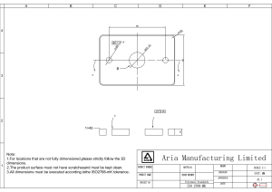
•The bore. It gets an ISO 286 tolerance, Ø25 H7. H7 defines the hole only: its limits are 25.000 to 25.021 mm. It does not say whether the assembly is a clearance, transition or interference fit. The mating shaft decides that. A Ø25 H7/g6 pair has a clearance of about 0.007 to 0.041 mm. A Ø25 H7/p6 pair has an interference of about 0.001 to 0.035 mm, which is one of the tight fits. If easy assembly and free rotation matter, the print of the shaft should call a slip fit clearance such as g6
- The hole positions. The two mounting holes get a position tolerance, because the general tolerances have no value for position. The print locates them with a position tolerance of Ø0.2 to datums A and B. The 90 mm distance between the two holes is a theoretically exact dimension in a box, so general tolerances do not apply to it. The print also has to say how the hole pair is located relative to the bore axis (datum B). If the pair must not rotate about that axis, it needs an orientation datum and the matching theoretically exact dimensions. If rotation is allowed, the print should say so.
- The mounting face. It gets its own flatness tolerance of 0.05 mm. The 1989 class K flatness value for this 120 mm face is 0.4 mm, which is too loose for a face that seats against the motor.
None of the remaining features meets another part in a critical way, so none of them needs a callout. Only three features need extra care in machining and inspection. The print stays clean, and the cost goes where the function needs it.
How to indicate ISO 2768 on an engineering drawing
A tolerance class only helps when the print states it clearly and in the standard form. If a feature needs tighter tolerances than the general standard gives, give it individual tolerance indications where the machinist is expected to look. A missing or unclear callout is how parts get made wrong. The three steps below describe the 1989 practice, which you will meet on existing prints.
Choose Your Tolerance Class Combination
Part 1 sets tolerances for linear and angular dimensions and uses a lowercase letter: f, m, c, or v. Part 2 used an uppercase letter for geometrical tolerances: H, K, or L. Write them together, linear class first, as in mK. This pair is the tolerance class designation. Pick the tolerance class your manufacturer can hold in normal machining. A tighter class costs more on all dimensions, so avoid it unless the whole part needs it.
Add the General Note to the Title Block
A legacy note names the standard, the class letters and, to be unambiguous, the edition:
Governing editions: ISO 2768-1:1989 and ISO 2768-2:1989
If only linear and angular dimensions need general tolerances, the note is ISO 2768-m. The note covers dimensions and features within the scope of the cited standard that have no tolerance of their own. Without class letters there are no tolerances to look up. On Figure 1, the 120 mm, 80 mm and 10 mm sizes take their tolerances from this line.
Override Where Needed
An individually specified tolerance takes precedence over the corresponding general tolerance. It can be tighter or looser than the general value. It replaces only the same kind of requirement: an individual size tolerance such as H7 replaces the general size tolerance, but it does not cancel the general geometrical tolerances that still apply to that feature. Put each individual tolerance indication right on its feature, because a callout buried in a notes block is easy to miss.
On the plate, the bore reads Ø25 H7. The two mounting holes carry a position tolerance of Ø0.2 to datums A and B. The mounting face carries a flatness tolerance of 0.05. All other dimensions stay under the general tolerances.
The Current Standards: ISO 2768:2026 and ISO 22081
Two documents now do the job that ISO 2768-mK once did: ISO 2768:2026 for general size tolerances, and ISO 22081:2021 for the rules of general geometrical specifications. Neither is a drop-in replacement for the old two-letter code, and you must not search-and-replace mK with either one.
ISO 2768:2026: General Size Tolerances
ISO 2768:2026 (Edition 2) was published on 9 November 2026 by ISO/TC 213. It replaces ISO 2768-1:1989.
- What it gives: a system of tolerance limits, in tolerance classes, for the general specification of linear and angular sizes.
- What it covers: features with a nominal linear size from 0.5 mm up to and including 4000 mm, and features with any nominal angular size.
- How it is meant to be read: the limits are intended for use with the default specification operators of the ISO GPS system. ISO 14405-1 and ISO 14405-3 give further information on sizes and these operators.
- What it does not cover: other kinds of dimensional specification, such as linear distances and angular distances. ISO 14405-2 is the reference for those. A center-to-center distance between two holes is a linear distance, so it needs its own specification.
- How it combines: it can be used on its own, or together with ISO 22081 or another general-specification document, as long as the interaction is described without ambiguity. ISO 8015 explains the general specification principle behind this.
ISO 22081:2021: General Geometrical and Size Specifications
ISO 22081:2021 (Edition 1) was reviewed and confirmed in 2026, so it remains current. It replaced ISO 2768-2:1989.
- What it gives: rules for the definition and interpretation of general geometrical specifications and general size specifications, as defined in ISO 8015:2011, 5.12.
- What it covers: integral features, including features of size. It does not apply to derived features, such as axes, or to integral lines.
- What it does not cover: dimensions other than linear or angular sizes, and general specifications defined in other standards.
- What it does not do: it does not hand you an H/K/L-style table to pick a letter from. The general geometrical values and the datum system must be stated explicitly, on the drawing or in a document the drawing references.
Using Them on a New Drawing
- Cite ISO 2768:2026, with the year, for general size tolerances, and choose the class from the official text.
- Cite ISO 22081:2021, or another stated document, for general geometrical specifications, and give the values and the datum system.
- Describe how the documents interact, so that no feature is covered twice or left uncovered.
- Specify dimensions outside the scope of ISO 2768:2026 individually, or cover them through another explicitly invoked and applicable specification. Do not assume that the ISO 2768:2026 size-tolerance note covers them.
This article does not reproduce the class tables or the title-block wording of ISO 2768:2026. Read them in the official text before you put them on a drawing.
Common Mistakes When Using ISO 2768
Most problems come from five habits: reading the class wrong, asking for more than the part needs, assuming the note covers everything, mixing editions, and ignoring the material.
Misinterpreting Tolerance Classes
This mistake is mixing up the class letters. In the 1989 system, lowercase letters (f, m, c, v) belong to Part 1 and set tolerances for linear and angular dimensions. Uppercase letters (H, K, L) belong to Part 2 and set geometrical tolerances. A designation such as ISO 2768-mK reads the same way every time: lowercase first, uppercase second. Swapping the letters gives the wrong deviations. On the 80 mm width of the plate, class m allows ±0.3 mm and class c allows ±0.8 mm. Check the table before you release the drawing.
Over-Tolerancing Leading to Increased Costs
This mistake is asking for a tighter class than the part needs. Tight tolerances mean slower CNC machining, better fixturing and more inspection, and a general note applies them to every dimension it covers. For example, legacy class f would put ±0.15 mm on the plate’s 80 mm width, and nothing on the plate depends on that. Choose the loosest class that still works, and use individual tolerances only on the features that need them.
Assuming the Note Covers Everything
A general note covers only the requirements within the scope of the cited standard. Under the 1989 system, reference dimensions and theoretically exact dimensions are excluded from Part 1. Part 2 does not specify general tolerances for position, cylindricity, angularity, coaxiality, line profile, surface profile, or total run-out. Non right angular dimensions may still receive general angular tolerances under Part 1. Under ISO 2768:2026, linear and angular distances are outside the scope of its general size specifications.
Neglecting Material Properties
This mistake is picking a class without thinking about the material. The tolerance values do not change with material, but the part does. Plastics flex and expand with heat. A thin aluminum plate can move after machining. A class that is easy to hold on a steel block may be hard to hold on these parts. Tell the manufacturer the material when you choose the class, and call out critical features directly. Different processes also hold different tolerances. CNC machining, sheet metal fabrication and molding all behave differently.
ISO vs. ASME Tolerance Standards
ISO standards such as ISO 2768 and ISO 286 are widely used in Europe, the UK, Turkey and parts of Asia. ASME standards are more common in the United States. Which one governs depends on where the part is designed and who inspects it. Many CNC machining and manufacturing shops read both.
ISO 2768 defines general tolerances for parts produced by machining or other material removal processes. ISO 286 establishes a code system for tolerances on linear sizes of cylindrical features and features formed by two parallel opposite surfaces. It also defines the terminology and principles of fits between mating features of size
On a drawing that explicitly invokes ISO 2768, its general tolerances apply only within the scope of the cited edition and where the corresponding requirement is not individually specified. Individual tolerances may be tighter or looser than the general values.
In that case an individual tolerance such as an ISO 286 fit goes on the feature. The individual tolerance always outranks the general note. Once a dimension carries an ISO 286 fit, ISO 2768 no longer governs its size.
ASME standards are better known for geometric dimensioning and tolerancing (GD&T). GD&T is a precise system for defining and communicating engineering tolerances. Linear tolerances only address size. GD&T controls the geometric relationships between features, so parts work together in assembly. ISO 1101 and ASME Y14.5 govern GD&T. The two are close but not identical.
| ISO Standard | Related ASME standard or practice | Application | Key Difference |
|---|---|---|---|
| ISO 2768 :1989 | ASME Y14.5 (a GD&T rule system, not a general tolerance table) | General tolerances for sizes and geometry that have no tolerance of their own, as cited on existing drawings | The 1989 pair is a ready-made class system. ASME prints usually state their own general tolerances in the title block. |
| ISO 2768:2026 | ASME Y14.5 and the title-block tolerances on the print | General tolerances for linear and angular sizes with no tolerance of their own | The class tables come from the official 2026 text. Linear and angular distances are outside its scope and need their own specification. |
| ISO 22081:2021 | ASME Y14.5 | Rules for general geometrical specifications | It gives rules, not an H/K/L-style table. The values and the datum system must be stated on the drawing or in a referenced document. |
| ISO 286 (grades 6, 7, 8) | ASME B4.2 (metric fits). ASME B4.1 for inch cylindrical fits. | Limits and fits for shafts and holes | B4.2 follows the ISO 286 system for metric sizes. B4.1 uses its own inch fit classes. |
| Angular sizes: ISO 2768-1:1989, Table 1.3 (legacy) and ISO 2768:2026 (current) | No direct ASME table | Bevels, tapers and other angles | ASME prints state angular tolerances in the title block or on the feature. |
| ISO 1101 (geometrical tolerancing) | ASME Y14.5 (GD&T) | Form, orientation, location and run-out | The two are close but not identical. |
The ASME column lists related standards or practices. They are not direct equivalents, and none of them can be swapped in for the ISO document in the same row.
How to Choose the Right Tolerance
Choosing a tolerance is a key decision in design and manufacturing. It affects how the part functions, how it fits, what it costs, and how easy it is to make. The right tolerances let parts assemble and run in their working environment, without extra cost or machining difficulty. Different processes often use a mix of unilateral and bilateral tolerance schemes on dimensions, and for fits this includes various slip fit toleranceclasses and applications, so start from how the part is made and what it must do. Then use the table below to find the tolerance standards that fit.
The table below gives examples of the standards to consider for a new drawing. It does not assign a class by product category. The class for general size tolerances depends on the function of the part and on the accuracy your shop normally holds, and you take it from the official text of ISO 2768:2026.
| Application | Description | Recommended tolerance standard | Reason for tolerance choice |
|---|---|---|---|
| Precision machined parts | Bores, sealing faces, and other features that set accuracy | ISO 286 and ISO 1101 on critical features. General sizes under ISO 2768:2026, with a finer class only if the function requires it. General geometry defined under ISO 22081:2021. | Function depends on fit and form, so the tolerances go on the feature itself. A finer general class raises cost on every dimension it covers. |
| Interchangeable mechanical parts | Parts made in batches that must swap without fitting | ISO 286 on mating sizes. General sizes under ISO 2768:2026. | Mating sizes need tolerances that hold in every batch.Choose the general class from what the process holds in normal production. |
| General mechanical assemblies | Brackets, plates, and housings that bolt together | General sizes under ISO 2768:2026. General geometry and datums stated explicitly per ISO 22081:2021. Individual tolerances on mating features and hole positions. | Bolt clearance may absorb small errors, but that has to be confirmed for each assembly. |
| Large fabricated structures | Welded frames and weldments | ISO 13920 | Welding heat distorts the part, so machined tolerances are unrealistic. |
| Plastic components | Molded housings, clips, and covers | ISO 20457 | Shrinkage and warp make metal-style tolerances unrealistic. |
| Shafts and holes for rotating components | Journals and bearing seats | ISO 286 fits. Run-out called out with ISO 1101. | The fit class sets the clearance. Run-out controls how the part turns. |
| Sheet metal parts | Bent and cut brackets and panels | Bent and cut brackets and panels Individual tolerances on critical bends, cutouts and hole positions. Other sizes under the general size tolerance, with the class agreed with the fabricator. | Bending and forming processes hold different accuracy from machining, so confirm what the shop can hold before you choose a class. |
| Electrical enclosures and casings | Boxes, covers, and panels with cutouts | General sizes under ISO 2768:2026, with tighter individual callouts on cutouts and seal lines | Lids, gaskets, and cutouts need tight tolerances to line up. |
| Consumer product components | Visible housings, buttons, and trim | ISO 20457 for molded parts. ISO 2768-m for machined parts. | Gaps and flush fit matter more to the user than absolute size. |
Existing drawings. Many existing prints cite ISO 2768-m or ISO 2768-mK, edition 1989. Keep reading and machining those prints as written, using the 1989 tables in this guide. Confirm the governing edition before you quote, as described earlier.
Find the row closest to your part. Then choose the general size class from the official text of ISO 2768:2026, based on function and normal shop capability. Define the general geometrical requirements and datums explicitly under ISO 22081:2021 or another stated document, and add individual tolerances only where a feature needs them. For drawings that follow ASME, use Y14.5 for geometric callouts and B4.2 for metric fits.
Conclusion
1989 Part 2 has been replaced by ISO 22081:2021. The 1989 tables remain essential for reading the many drawings that still cite ISO 2768-mK. New drawings should state the edition, give general size tolerances under ISO 2768:2026, and define general geometrical tolerances and datums explicitly. Critical features still need their own tolerances, such as an ISO 286 fit. For features that depend on how they relate to each other, GD&T, short for geometric dimensioning and tolerancing, and its related standards go much further.
Aria Manufacturing provides custom CNC machining and manufacturing services built around the dimensions and tolerances on your drawing. You can also draw onAria’s broader manufacturing services from prototyping to production. Send your drawing with the general tolerances note, the edition it follows and any special callouts, and the team will check it against what the process can hold.
