Machining Copper on a CNC Machine: Complete Process

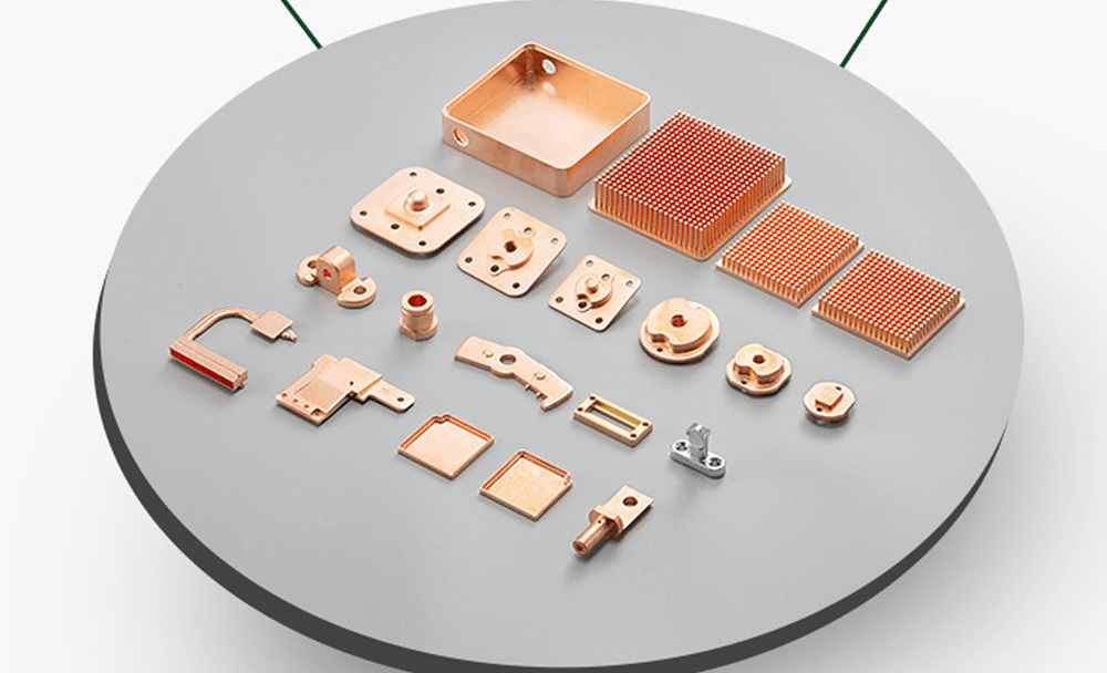
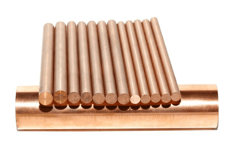
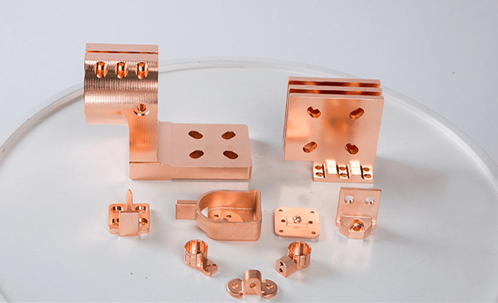
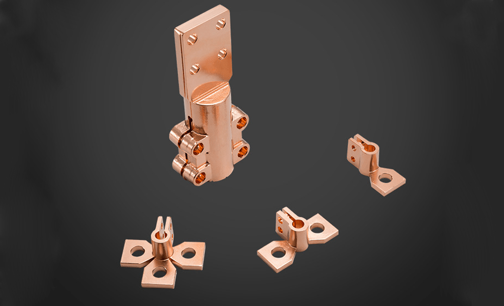
Copper and its alloys are widely used in modern mechanical engineering as structural, antifriction, electrical and other materials.

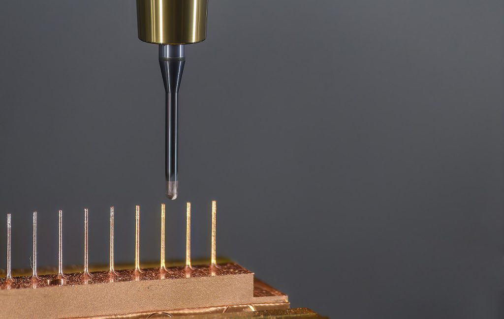
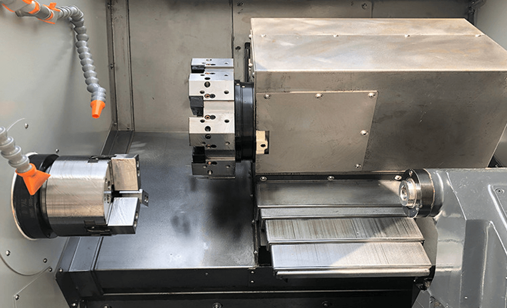
CNC machining is a manufacturing process in which pre-programmed computer software directs the movement of tools and machines in the factory. This process can be used to control a wide range of complex machines, from grinders and lathes to mills and routers.

With CNC copper machining, three-dimensional cutting tasks can be performed in a single set of prompts. Short for “computer numerical control,” the CNC (Computer Numerical Control) process runs as opposed to – and thus replacing – the limitations of manual control, where a direct operator is needed to prompt and guide the machine tool commands via levers, buttons and wheels. To the observer, a CNC system may seem like a collection of ordinary computer components.

How Does Machining Copper Work?

machining copper parts

When a CNC system is activated, the desired cuts are programmed into the software and specified according to the respective tools and machines. These machines and tools will then perform the assigned tasks, like a robot.

The Advantages Of Copper Machining

CNC Machining Copper

Copper is one of the most common structural materials widely used in various industries. Copper has long been mined and processed by man – largely due to the comparative availability of ore, low melting point and plasticity of the metal itself. At the same time, copper has a number of valuable properties: malleability, high thermal and electrical conductivity, sufficient strength and, at the same time, ductility.

And it exhibits excellent corrosion resistance and offers excellent thermal and electrical conductivity, making it ideal for use in electronics, communications equipment, and similar devices. Copper Alloys 10100 and 11000 have high electrical and thermal conductivity, in addition to excellent hot and cold workability.

All this leads to the widespread use of copper – in electrical engineering, for the manufacture of seamless pipes and heat exchangers, as a coating for plain bearings, and also as an integral component for various alloys (duralumin, bronze and even pure gold). In addition, copper is an essential element in the body of higher animals and humans.

Features of copper processing and requirements for cutting tools

Due to its ductility, copper lends itself well to machining (forging, stamping, and cutting). It was this property that determined the rapid “technological explosion” of mining, processing and use of copper in ancient times (in the “Bronze Age” weapons and household items were made of bronze – an alloy of copper and tin).

Today, copper blanks are successfully processed mechanically. However, during contact machining (for example, on a CNC milling machine), a number of conditions must be observed to obtain high-quality copper components. As noted above, the main property of copper is high ductility. This leads to the fact that during the cutting process, the cutter tends to “bog down” in the material. To obtain high processing performance and obtain high-quality products, you should:

  • use a carbide cutting tool;
  • maintain a high degree of sharpness of the tool (cutter);
  • do not exceed the recommended feed and spindle speed (do not “force” the processing speed);
  • be sure to use a cutting fluid (coolant);
  • take measures to remove chips from the cutting zone (and also prevent chips from clogging the spiral grooves of the cutter).

Coolant Application

copper machinig

When processing copper on a machine, the latter must be equipped with a lubrication and cooling system. In the case of copper, the main function of the coolant is precisely lubrication, since due to the relatively “soft” processing conditions, a significant increase in temperature in the cutting zone is not observed (in comparison with stone milling, for example).

As a coolant, it is recommended to use a special composition of WD-40, in extreme cases – machine oil. The use of an aqueous solution of soda (used mainly as a “base” coolant) when milling copper is not enough – due to low lubricating properties.

The supply of coolant to the cutting zone can be carried out by a standard or optional system of a milling machine. In the simplest case, the coolant system includes a tank (reservoir) for storing a supply of liquid, a pump for creating pressure in the system, flexible connecting lines and a spray nozzle installed “under the cutter”. 

When CNC Copper machining, coolant should be directed either at the cutter or directly into the machining area. In this case, the coolant will perform the additional function of cleaning the cutting zone from chips.

Recommended Milling Modes

The optimal processing modes on a machine can only be established experimentally. For each specific case – the state of the cutter, the type of workpiece and the complexity of the control program – its own, unique processing mode will be optimal. However, the general recommendation is to remove no more than 0.2 mm of material per cutter pass.

The tool feed should be maintained at 4-6 mm/s, and the depth of cut should not exceed 30% of the cutter diameter (depending on the machining strategy – see below). The spindle speed should be set small, and the processing modes should be “forced” only when using a resistant cutting tool with high hardness.

Control Program Development Strategy

coppper parts

The quality of copper processing on a modern CNC machine depends not only on the hardware (the design of the machine itself and the type of cutting tool), but also largely on the correct processing strategy implemented in the control program. 

The control program is a route of movement of the cutter, built on the basis of a mathematical model of the finished product. The control program also contains information about the processing modes and the type of cutting tool used for each technological transition (roughing, finishing, etc.). 

To create control programs, a CAM environment is used, for example, ArtCam, MasterCam SolidCam (Solidworks application), etc. Depending on the set of utilities of a particular program, the strategy for creating the optimal trajectory of the cutter will vary.

Machinability Of Copper

CNC turning machine

Copper is the next highly ductile FCC metal similar to aluminum, but has a higher melting point of 1083°C. In general, common copper alloys also have good machinability due to the same reasons as aluminum alloys. Although the melting point of copper is higher, it is not high enough for the temperatures generated by shear in the plastic flow zone to have a significant effect on tool life or performance.

For processing, tools are used both from high-speed steel and from hard alloy. Sufficient tool life is provided, tool wear results in a flank wear pad or wear crater, or both, but no detailed study of wear mechanisms has been reported.

The most important area for the machining of copper-based alloys is the mass production of electrical and other fittings on high-speed automatic machines. Such machines are mainly high-speed lathes, in which, however, the use of relatively small diameter brass wire limits the maximum cutting speeds to 140-220 m / min, although if necessary the tool provides good work at a much higher cutting speed.

The Cutting Force in CNC Machining

The cutting forces that occur when cnc machining pure copper are very high, especially at low cutting speeds, which, as in the case of aluminum machining, mainly caused a large contact area on the front surface, leading to the formation of a small shear angle and to thick strand. For this reason, copper with high electrical conductivity is considered one of the most difficult materials to machine.

For example, when drilling deep holes, the cutting forces are often so great that they cause the drill to break. Additional problems when machining pure copper are poor surface quality, especially at low cutting speeds, and high strength of entangled hard-to-clean chips.

How to improve the quality of copper machining?

The quality of Copper CNC machining can be somewhat improved by cold plastic deformation, but a significant improvement is achieved by alloying.

The reduction in cutting forces as a result of cold working, resulting in a smaller contact area, a larger shear angle, and thinner chips. When machining single-phase brass 70/30, the cutting forces are less, however, a noticeable decrease in cutting forces is observed in two-phase brass 60/40, when machining which the cutting forces are lower over the entire range of cutting speeds, the chips are thinner, and the contact area on the front surface is small. The minimum cutting forces are noted in alloys with a high zinc content, in which the relative content of the b-phase is higher.

CNC Machine Programming

In CNC manufacturing, machines are operated through numerical control, where a software program is specified to control an object. The language behind Copper CNC machining is alternately called G-code, and it is written to control various behaviors of a machine respectively, such as speed, feedrate, and dispatch.

Essentially, CNC machining allows pre-programming the speed and position of machine tool functions and running them through software in predictable, repetitive cycles, all without fail with human participation. Because of these capabilities, the process has been applied across all areas of the manufacturing sector and is especially important in the metal manufacturing sectors such as stainless steel, aluminum, and plastics.

To begin with, a 2D or 3D CAD drawing is formed, which is then translated into computer code for the CNC system to execute. After the program is entered, the operator runs it for a test run to make sure there are no errors in the coding process.

Open/Close Loop Machining System

The position control is defined through an open-loop or closed-loop system. Previously, signals flowed in only one direction between the controller and the motor. However, with a closed-loop system, the controller has the ability to receive feedback from which errors can be corrected. Thus, a closed-loop system can correct for velocity and position anomalies.

In Copper CNC machining, motion is usually directed through the X and Y axes. In turn, the tool is positioned and guided through a stepper motor or servomotor, which reproduces precisely defined movements: Specified by G-code. If force and speed are minimal, the process can be run through open-loop control. For everything else, closed-loop control is needed to ensure the speed, consistency, and accuracy needed for industrial applications, such as metalwork.

Fully Automatic CNC machining

In today’s CNC protocols, the production of parts and copper parts, through pre-programmed software, has been largely automated. The dimensions of a given part are set in place using computer-aided design (CAD) software and then converted to the actual finished product using computer-aided manufacturing software (ORANGE).

Any particular job may require a variety of machine tools, such as drills and cutters. To meet these needs, many machines today combine many different functions into one cell. Alternatively, an installation might include several machines and a set of robotic arms that move machined copper parts from one application to another, but with everything controlled by the same program.

Regardless of the setup, the CNC process allows for consistency in the production of parts that would be difficult, if not impossible, to reproduce manually.

Author

Gavin Leo is a technical writer at Aria with 8 years of experience in Engineering, He proficient in machining characteristics and surface finish process of various materials. and participated in the development of more than 100complex injection molding and CNC machining projects. He is passionate about sharing his knowledge and experience.