Selecting the appropriate metal material is absolutely vital in CNC machining operations. This crucial decision directly impacts five key performance factors: machinability, cost efficiency, mechanical strength, corrosion resistance, and ultimately the functional performance of your final product.
At Aria Precision Manufacturing, we’ve successfully processed thousands of metal components across diverse industries, accumulating extensive expertise in material optimization.
If you are not yet familiar with metal CNC machining Process and don’t know which materials to choose for your project, please take a few minutes to read this article to help you make a wise decision.
What is Metal CNC Machining?
CNC metal machining (Computer Numerical Control) is the process of removing material from metal stock using precision cutting tools with the use of an automated machine such as a lathe or a mill. A CNC machine has the ability to produce accurate parts with tight tolerances with consistency and efficiency.
How Does Metal CNC Machining Work?
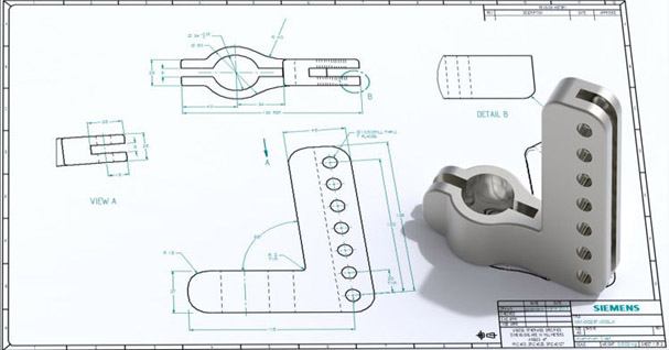
Drawing Design
The initial part of the machining process. Can range from a rough hand sketch to a complete engineering drawing. It should include all the necessary dimensions and tolerances required for the part. It can also be modelled on CAD (computer aided design) software.
DFM
Design for manufacturability is the review of the design to make sure it is able to be machined and make any adjustments to increase efficiency of the manufacturing process E.G. reduce the amount of tool changes required.
Material Selection
Material selection comes down to the requirements for weight, cost, corrosion resistance, tensile strength and application for the part being made. The chosen material is a key factor in determining the manufacturing process and cost efficacy of the part. Most commonly used materials used are mild and hardened steels, brass, aluminum and stainless steel.
Machine Selection
The machine selection largely depends on the complexity of the part at hand. A CNC lathe is commonly used for round and lesser complex parts. Whereas a CNC milling machine is used for more complex parts with the option to have a 4 or 5 axis machine for the more complex geometries of the CNC machining process.
Programming
CNC programming is most commonly done using CAD/CAM (computer aided design / computer aided manufacturing). Toolpaths are programmed off a CAD file of the 3D model with the operator setting the speeds and feeds of the CNC machine and posted into G code format for the machine to be able to read.
Machine setup
The machine setup involves the holding of the metal stock, the setup of tooling and work offsets. Simulations can be run on the CAD/CAM software and on the CNC machine (depending on the brand and age of the machine) to ensure the CNC machining process runs safely and efficiency.
Machining
Once the CNC machine setup is completed, the machining process of removing material starts. The CNC machine executes the programmed toolpaths and runs the material removing process through turning, milling, drilling or tapping processes. Measurements can be made throughout the CNC machining process to be sure the part remains within general tolerances.
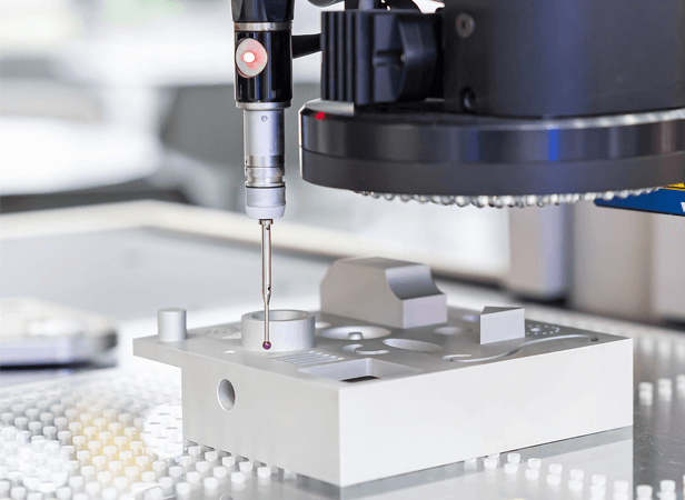
Surface And Tolerance Inspection
This is the final stage of the CNC machining process, parts are checked using precision measuring equipment such as verniers, micrometers, CMM machines and surface roughness testers to ensure the part meets all the manufacturing requirements.
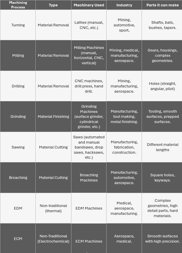
Types Of Metal CNC Machining Process
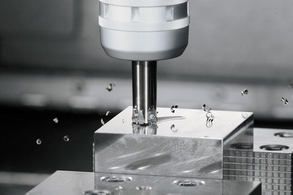
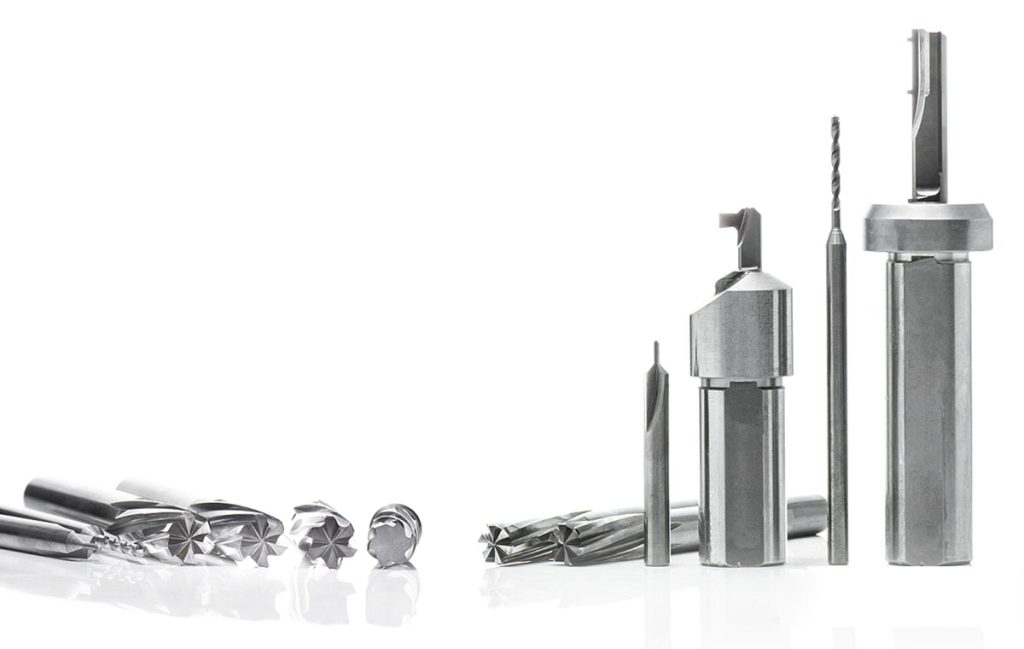
Milling
CNC milling is the process of removing material through a rotating cutting tool. The tooling consists of tools such as endmills, facemills, threadmills and drills. A CNC milling machine has the ability to machine complex geometries and move across multiple axis. A CNC mill most commonly has between 3 to 5 axis, with 5 axis machines being able to make much more complex parts than a 3 axis and, in less operations.
Turning
Turning is a CNC machining process where the material stock rotates while the tooling remains stationary. This is done on a CNC lathe and is ideal for round parts such as shafts, bats, bushes and tapers. This process is done with very high precision using tooling such as external turning tools with inserts such as a TNMG or WNMG, internal turning tools such as boring bars, threading and grooving tools both for internal and external.
Drilling
Drilling is the process of creating round holes by feeding the drill into metal stock. Drilling is used on both a CNC mill and a CNC lathe. With the drill rotation on a mill and it remains stationary for a lathe. There are many different variants of drills used on a CNC machine such as a U-drill for larger holes, indexable head drills for medium holes, solid carbide drills for smaller holes and HSS (high speed steel) as a slower cost-effective solution for jobbing small to medium holes.
Grinding
Grinding uses an abrasive wheel to achieve very fine and accurate metal finishes. Grinding has the ability to produce extremely tight tolerances with minimal material removal. It is great for finished parts such as parallel blocks and measuring equipment such as gauge blocks.
EDM Machining
EDM machining (electrical discharge machining) uses controlled electrical sparks between an electrode and the workpiece to remove material. It is ideal for hard materials and very intricate shapes that cannot be produces with traditional cutting tool and machines. EDM machines have the ability to produce extremely smooth surfaces with high precision parts.
What are the Common Metal Materials Used in CNC Machining?
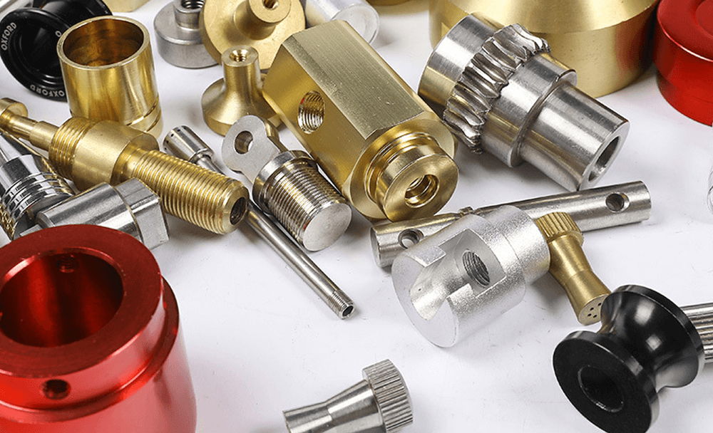
Metal materials are most commonly used in the manufacturing industry, with the most common CNC machining metals being steel, aluminium, stainless steel and brass.
The choice of metal plays a major role in the performance of the part, the surface finish, overall cost, tool wear and can vary depending on specific properties needed for the part.
Aluminum
Aluminium due to its good mechanical properties is one of the most widely used metal in CNC machining with it being lightweight, corrosion resistant and having great dimension stability. It is also a joy to machine, being able to run parts at high speed with minimal tool wear and easy to clean swarf.
Brass
Brass is widely used for fittings, bushes, valves and electrical components. It is very easy to machine and run production amounts with minimal tool wear and dimension stability on machined parts.
Steel
Steel is highly used and valued for its high strength and versatility. It being suitable for a wide range of industrial high precision parts. Mild steels such as 1020 and 1045 are great for general purpose components such as shafts and brackets. Metal alloy steel such as 4140 and 4340 provide better wear resistance and higher toughness making them a great choice for tooling, mining and weight bearing parts.
Stainless Steel
Stainless steel is a great selection when durability and corrosion resistance is needed. Steel grades such as 304 and 316 are most commonly used in marine, food and medical industries. Whereas 17-4 PH offers great strength corrosion resistance for industries such as aerospace and defence components.
Mild Steel
Great for general purpose components with its strength and affordability and is widely used in metal CNC machining around the world due to its dimension and machining stability. It’s poor corrosion resistance makes it a great metal for welding and fabrication also.
Copper
Copper is well regarded for CNC machining due to its electrical and thermal conductivity. Commonly used in components such as heat exchangers, electrical terminals and specialised industrial parts. Copper can be quite difficult to machine due to its softness and poor chip removal at times.
Titanium
Titanium is usually chosen for impressive hardness, low weight and corrosion resistance. With a fantastic strength to weight ratio it makes it a great metal for industries such as aerospace, medical and automotive. It is well known as one of the hardest metals to machine due to its hardness and tool wear it can cause. It also has a high price point.
Metal CNC Machining Guide
The Differences Between Metal Machining & Fabrication?
Document
Process
Metal Machining
Metal Fabrication
Cost
Expensive
Cheap
Tooling
CNC lathes,mills and drills
Bending machines,presses,saw and welding machines
Precision and Accuracy
High
Low
Production Speed
Slow
Fast
Project Complexity
High
Low
FQAs
Q.What is the advantage of CNC machining?
A:The ability to create complex and accurate parts with fast turnaround with the ability to machine complex geometries.
Q.How accurate is CNC machining?
A:CNC machines can typically hold tolerances of ±0.01mm to ±0.05mm with high end machines able to hold even tighter tolerances.
Q.Is CNC machining expensive?
A:Costs depend on the material used, machine time, tolerances, complexity of the job and machinery required to make the part. A simpler part can be costly for CNC machining whereas a more complex part requiring more precision can be more cost effective.
Q.How do I get a part CNC machined?
A:A part can either be provided to a machine shop and revered engineered, a drawing provided or a CAD file in the form of STEP, IGES or STL files.