Understanding Injection Molding Tolerances and Standards

Plastic Moulding Tolerances

Share:

Table of Content

Table of Content

I work with design engineers every week who need to specify injection molding tolerances correctly the first time. This guide covers what tolerances are, the types I use on drawings, the standards that govern them, and the factors that decide whether a part holds dimension or fails inspection.

What Are Injection Molding Tolerances?

Injection molding tolerances are the acceptable dimensional deviations on a molded part. I write them as plus-or-minus values—for example, ±0.1 mm or ±0.005 in—next to the dimension they apply to on a drawing.

A tolerance tells the molder how much variation is allowed and how critical that dimension is to part function. A tighter tolerance forces tighter control of mold steel, resin selection, process parameters, and inspection. That control costs money.

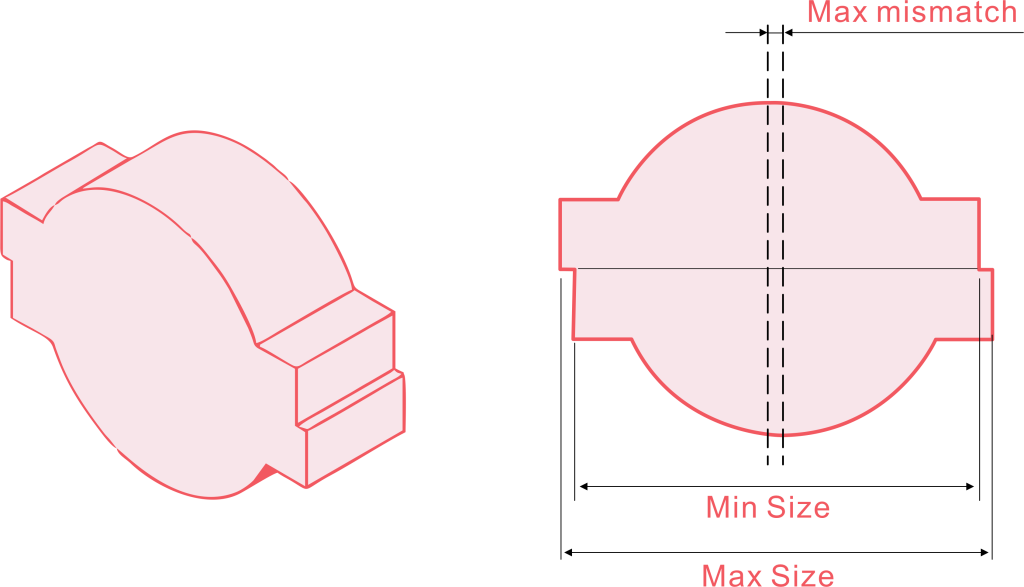
What is Plastic Moulding Tolerances

Types of Injection Molding Tolerances

Commercial Tolerances

Commercial tolerances run around ±0.1 mm (±0.005 in) for features up to 100 mm. They use standard mold steel and standard process control, and they produce parts at the lowest cost.

Fine (Precision) Tolerances

Fine tolerances run ±0.025 to ±0.05 mm. They require hardened mold steel, climate-controlled production, and narrow process windows.

Machining Tolerances

Machining tolerances apply to the mold cavity itself, typically ±0.005 in (±0.127 mm). They set the floor for what the molded part can hold.

Resin Tolerances

Resin tolerances apply to the finished plastic part after shrinkage. They are always wider than machining tolerances because the plastic continues to move as it cools.

Linear Dimension Tolerances

Linear tolerances apply to length, width, and height. Larger dimensions need wider tolerance bands because shrinkage compounds with length.

Hole Diameter Tolerances

Hole diameter tolerances apply to round features molded with core pins. Larger holes need wider tolerance bands because shrinkage is proportional to diameter.

Blind Hole Depth Tolerances

Blind hole depth tolerances apply to holes that don’t pass through the part. Deeper holes need wider tolerance because the cantilevered core pin deflects under injection pressure.

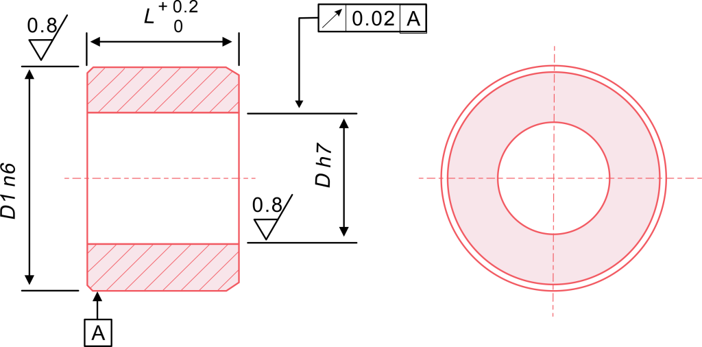
Concentricity and Ovality Tolerances

Concentricity and ovality tolerances apply to round features that must run true. They control shafts, bearing seats, and rotating components.

Flatness and Straightness Tolerances

Flatness and straightness tolerances apply to large flat surfaces and long thin features. Warpage breaks these tolerances first.

Angularity and Draft Tolerances

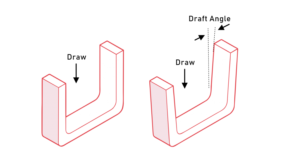
Angularity and draft tolerances apply to angled surfaces and the ejection tapers on vertical walls. Draft is typically 1° minimum, more for textured surfaces.

Draft Angle

Key Factors That Affect Injection Molding

Tolerances

Tolerances aren’t set by the drawing alone. They are the output of a system, and the following factors drive that system.

Material Selection and Shrinkage

Every plastic shrinks as it cools, and the shrinkage rate sets the tolerance ceiling. Amorphous polymers (ABS, PC, PMMA) shrink 0.2% to 0.8% and hold tight tolerance. Semi-crystalline polymers (PP, PA, POM) shrink 1.0% to 3.6% and need more process control. Glass fiber reduces overall shrinkage but creates directional shrinkage that can warp long parts

Typical Shrinkage Rates by Resin
MaterialShrinkage Rate
ABS0.4–0.7%
ABS/PC Blend0.5–0.7%
PC0.5–0.8%
PMMA0.2–0.6%
PS (GPPS)0.3–0.6%
PVC1.0–2.5%
PP (Homopolymer)1.0–2.5%
HDPE1.5–3.0%
LDPE1.5–3.6%
PA6 (Nylon 6)1.0–1.5%
PA661.5–2.0%
PA66, 30% GF0.3–0.7%
POM (Acetal)1.8–2.5%
PBT1.2–2.0%
PEEK1.0–1.3%
PPS0.6–1.4%

Wall Thickness

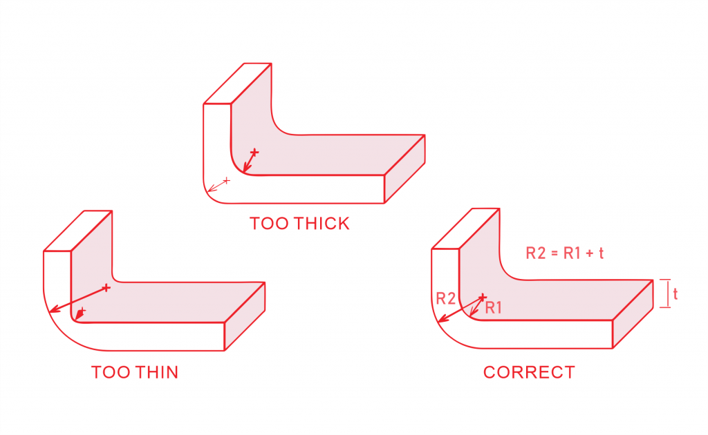
Wall thickness drives cooling rate and shrinkage uniformity. I keep nominal walls between 1.2 mm and 2.5 mm, hold variation within ±25% of nominal for amorphous resins, and within ±15% for semi-crystalline resins. Thickness changes must be gradual ramps, not steps.

injection molding wall thickness

Cooling

Cooling time and uniformity decide shrinkage and warpage outcomes. Cooling channels must sit close to thick sections, and flow rates must be balanced across the cavity. Uneven cooling produces hot spots that pull the part out of tolerance.

Mold Design

Mold quality sets the upper limit on achievable tolerance. Hardened steel holds tighter than aluminum, single-cavity molds hold tighter than multi-cavity, and gate location controls warpage. Core pin support, ejector layout, and parting line accuracy all add to the result.

Process Parameters

Injection pressure, hold pressure, melt temperature, mold temperature, and cycle time all change part dimensions. Skilled molders document these in a process sheet and lock them for production. Drift in any parameter shifts the part.

Part Geometry and Size

Larger parts have larger absolute tolerances because shrinkage compounds with length. Complex geometry with ribs and bosses adds variation because each feature cools at its own rate. A 300 mm dimension on a semi-crystalline material cannot hold ±0.1 mm under any condition.

Warpage and Thermal Expansion

Warpage is the result of differential shrinkage—one area shrinks more than another and the part bends. It breaks flatness and straightness tolerances first. Thermal expansion is separate and matters in service, especially when plastic parts assemble with metal ones.

Injection Molding Tolerance Standards

Four standards appear on production drawings most often.

ISO 20457:2018

ISO 20457:2018 is the current international standard for plastic molded parts. It defines tolerance grades (TG) by material group and part size, and requires inspection at 23°C ±1°C and 50% ±10% relative humidity.

DIN 16742

DIN 16742 is the German standard, used by European automotive suppliers. It separates mold-fixed dimensions from non-mold-fixed dimensions, with the latter carrying wider tolerance. TG6 is the standard group for general thermoplastics, ranging from ±0.07 mm to ±3.1 mm.

GB/T 14486-2008

GB/T 14486-2008 is China’s national standard for plastic molded part tolerances. The structure mirrors ISO 20457 and the values align closely with it.

SPI Tolerance Classes

The Society of the Plastics Industry defines three tolerance classes used in North America: Normal (commercial), Medium (fine), and Fine (precision).

Design Tips for Achieving Tighter Tolerances

When a client needs precision tolerances, I work through this list before tooling starts:

  1. Start DFM analysis at the concept stage, not after the mold is cut
  2. Hold uniform wall thickness within ±15% to ±25% of nominal
  3. Use ribs and gussets for stiffness instead of thicker walls
  4. Radius all sharp corners to reduce stress concentration
  5. Specify tight tolerances only on functional dimensions
  6. Choose amorphous resins (ABS, PC, PMMA) when possible—they hold tolerance better than semi-crystalline ones
  7. Plan gate location with mold flow analysis before cutting steel
  8. Allow draft angles of 1° minimum, more for textured surfaces
  9. Verify critical dimensions at T1 mold trial and adjust steel if needed
  10. Bring the molder and tooling shop into design reviews early

I also push back when a tolerance looks unrealistic. Asking for ±0.01 mm on a 200 mm polypropylene part isn’t engineering—it’s a problem waiting for production.

Written By

Coco is a mechanical engineer and content editor at Aria. She partners with process engineers and shop-floor teams across CNC machining, injection molding, sheet metal fabrication, and surface finishing — turning real production know-how into practical, honest guides for the people designing, specifying, and buying parts.

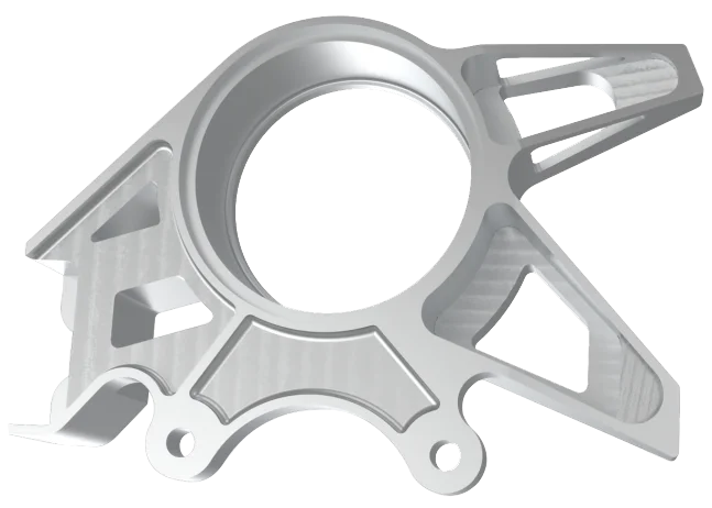
CNC milled aluminum precision part with complex geometry and multiple machining features

Custom Quality Parts By Aria

Send your specs. We’ll get back with a quote in 12 hours.

Scroll to Top