What Is Insert Molding: Benefits, Applications and Design
Written By: Gavin Leo
Update By:
Gavin Leo
Published:
Updated:
Share:
Table of Content
Table of Content
The technology of insert molding can provide durable, cost-efficient parts with complex geometries. It is often used in industries where a tough multi-material part is needed, such as in automotive, electronics, and medical applications.
I’ve been in precision manufacturing long enough to know that insert molding sounds straightforward until something goes wrong. Most of these failures trace back to decisions made early in the design process, before a single piece of steel was cut.
In this article, we’ll explore how insert molding Process, its applications, benefits, and why it’s an essential technique in modern manufacturing.
What Is Insert Molding?
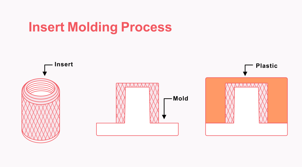
Insert molding is a injection molding process where a pre-formed component (typically metal) is placed into a mold cavity before plastic is injected around it, creating a single permanently bonded part.
The result is a single part that combines the strength or conductivity of metal with the geometry and weight savings of plastic.
How Does the Insert Molding Process Work?
The insert is placed into the mold cavity, molten plastic is injected under high pressure to encapsulate it, then cooled and ejected as a single integrated part.
Process Step by Step
Step 1: Insert Preparation
Every insert gets inspected before it goes near the mold. Dimensional check, surface condition, surface features (knurling, grooves, undercuts). Any contamination on the surface weakens the mechanical bond.
For high-performance resins like glass-filled nylon or PEEK, we pre-heat inserts before loading. This reduces thermal shock and the hoop stress that causes cracking around the insert after molding.
Step 2: Insert Placement
Two options: manual loading by an operator, or automated loading via robotic arms or bowl feeders. Manual works fine for low volumes and prototypes.
The mold must hold the insert precisely under injection pressure. Locating pins, spring fixtures, and vacuum-assist systems all serve this purpose. A floating insert during injection means a scrapped part and possibly a damaged tool.
Step 3: Resin Injection
Mold closes. Molten plastic (usually 200–300°C depending on material) is injected at high pressure, flowing around and encapsulating the insert.
Three parameters we watch closely: injection temperature, fill speed, and hold pressure. Hold pressure is what compensates for shrinkage during cooling. Get it wrong and you get voids or dimensional drift.
Step 4: Cooling and solidification
After the molten plastic has filled the cavity, it begins to cool down and solidify. Cooling takes time, as the plastic hardens and becomes a solid over the insert.
Cooling rate affects warp, residual stress, and dimensional accuracy.
Step 5: Ejection and Post Processing
When the parts have finally cooled and solidified, the two parts of the mold will be separated, and the completed parts will be ejected from the mold cavity.
At this point, the parts may still require some subsequent processing operations, such as deburring, heat treatment, and surface finishing.
Common Insert Types For Injection Molding
Here’s a visual overview of the six common insert types. A quick summary of each:
Threaded inserts
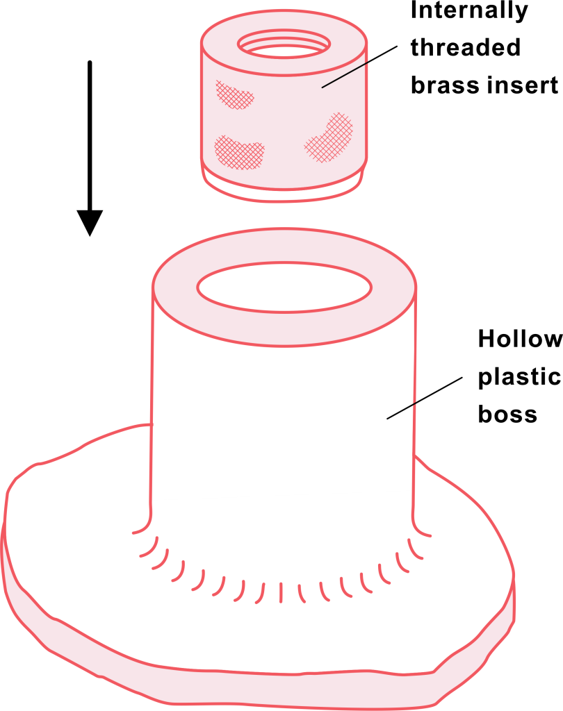
This type of Inserts are the most common. It is usually made of brass and sometimes of stainless steel. They can form a firm fixation point and can withstand repeated assembly and disassembly operations without causing damage to the threads. Compared with self-tapping screws in plastics, the built-in brass inserts have much better performance.
Pins and shafts
The pins and shafts are used for positioning, rotation or load transmission. They are commonly found in hinges and actuator components.
Bushings and sleeves
The bushings and sleeve are located inside the plastic housing, providing a wear-resistant surface for the bearings. The use of a metal-to-axis contact method instead of a plastic-to-axis contact method means that the service life will be significantly extended.
Electrical contacts and terminals
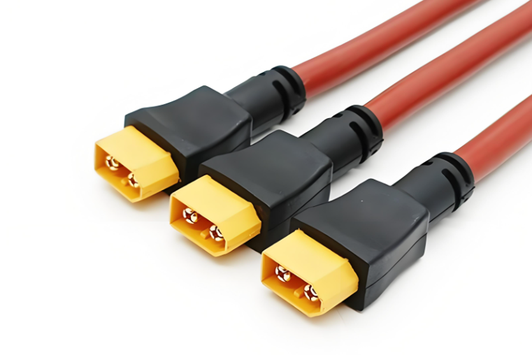
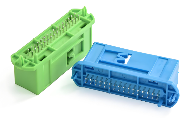
They are the backbone of most plastic connector bodies. The plastic handles insulation and form; the metal handles conductivity.
Blade inserts
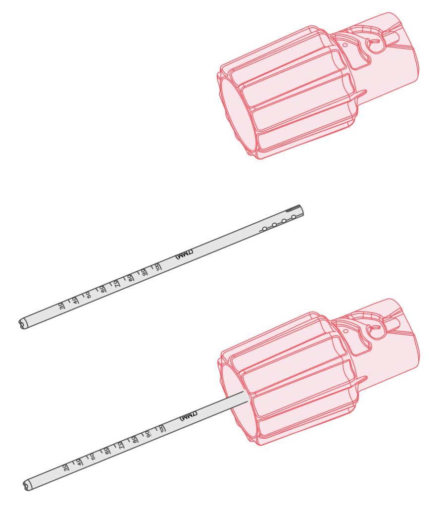
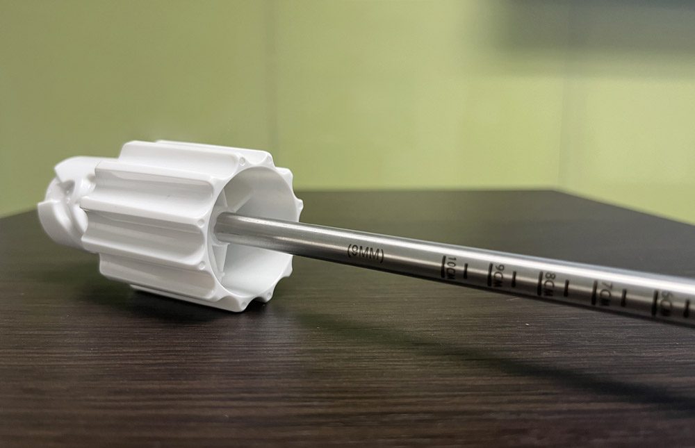
Blade inserts appear in cutting tools and surgical instruments where a metal blade is encapsulated in a plastic or rubber handle.
Reinforcing plates
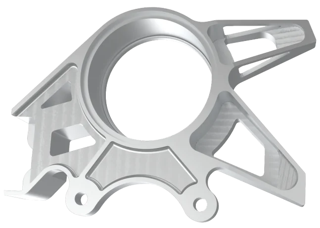
It add localized stiffness where plastic alone isn’t sufficient, without adding bulk to the whole part.
Insert Injection Molding Materials Selections
Insert Materials
Material
Best Used For
Brass
Threaded inserts; most common choice for machinability and predictable behavior
Stainless Steel
Corrosive environments, medical, food equipment
Aluminum
Weight-critical applications; softer, so avoid for heavily loaded threads
Copper
Electrical components needing high conductivity
Plastic Materials
Material
Strengths
Nylon (PA66/PA6)
Strong, heat-resistant, wear-resistant
Polycarbonate (PC)
High impact resistance, optical clarity
ABS
General purpose, good dimensional stability
POM (Acetal)
Low friction, tight tolerances
PBT
Electrical parts, chemical resistance
PEEK
Extreme temperature, medical, aerospace
Benefits Of Insert Molding
Strong Bonding
The insert and plastic are securely bonded, leading to strong, durable parts.
Cost Efficiency
By eliminating the need for additional assembly steps, insert molding reduces production time and costs.
Design Flexibility
The process allows for complex parts that integrate multiple materials (e.g., plastic and metal) in a single component.
Reduced Assembly Time
Parts are molded in one step, which eliminates the need for separate assembly processes and speeds up production.
Enhanced Durability
The combination of materials results in parts with enhanced wear resistance, strength, and performance.
Applications Of Insert Moldings
Insert molding shows up across almost every industry:
Automotive
Sensor housings, connectors, bracket assemblies. Common reason: eliminates assembly steps and reduces vibration-related failures.
Medical
Surgical instruments, catheter bodies, device housings. The ability to embed metal contacts or structural elements into biocompatible plastic makes insert molding essential here.
Consumer Electronics
Connector bodies, buttons, display housings. Your phone’s charging port is almost certainly insert-molded.
Aerospace and Defense
Avionics housings, connector shells, EMI shielding components where mil-spec tolerances are required.
Industrial Equipment
Tool handles, valve bodies, actuator components where metal strength meets plastic ergonomics.
Some of our most technically demanding insert molding work at Aria has come from EV clients, specifically battery management connectors and motor controller housings where thermal cycling specs are aggressive.
What is the difference between insert molding and overmolding?
Insert molding embeds a metal (or non-plastic) component into a plastic part in a single shot. Overmolding adds a second plastic or rubber layer over a previously molded plastic part in a two-shot process.
People mix these up constantly, so here’s the short version:
Insert Molding
Overmolding
What goes in first
Metal (or ceramic) insert
Molded plastic substrate
Bond type
Mechanical (knurling, undercuts)
Mechanical + chemical
Process shots
Single shot
Two shots
Tooling cost
Lower
Higher
Typical use
Electrical components, automotive, mechanical parts
Ergonomic handles, medical devices, sealing parts
The practical rule: if you need metal inside the part, it’s insert molding. If you need soft-touch or two-color plastic, it’s overmolding.
Design Guidelines for Injert Injection Molding
These are the issues I see causing problems most often:
Wall Thickness
Keep wall thickness around inserts at 0.8mm minimum, ideally 1.5–3.5mm. Too thin and you get cracking or poor retention. Too thick and you get sink marks and longer cycle times.
Corners
Eliminate sharp corners at insert-to-plastic transitions. Sharp corners concentrate stress. Add a minimum 0.5mm radius; 1mm is better.
Knurls and Ribs
Always add mechanical retention features to the insert surface. knurling, circumferential grooves, or ribs. Plastic does not chemically bond to metal, so surface geometry is the only thing keeping the insert in place.
Tolerance Planning
Account for shrinkage rates of the plastic material during design. Different resins shrink differently. Finalize tolerances with your molder before tooling is cut.
Gate Placement
The gate should allow balanced flow around the insert. Asymmetric fill can push the insert laterally or create weld lines on the insert surface. Both are problems.
Prevent Sink Marks
Maintain uniform wall thickness around the insert. Abrupt thickness changes cause differential shrinkage, leading to visible sink marks and internal stress.
Depth Ratio
For blind holes or bosses around an insert, keep the depth-to-diameter ratio under 3:1. Deeper than that risks incomplete fill and structural weakness.
Ejector Pin Location
Place ejector pins away from inserts and thin walls. Ejection force applied too close to an insert can crack the surrounding plastic or dislodge the insert during ejection.
Pre-heat inserts for engineering resins
For anything running above ~260°C melt temperature, pre-heat the inserts. It reduces thermal shock and cracking risk at the insert boundary.
How Aria Supports Insert Injection Molding
Before we cut any tooling, we run a material compatibility assessment on the insert-plastic pairing, including CTE mismatch and bond strength. Every insert mold goes through a three-stage validation: tool trials, dimensional verification, and pull-out force testing.
Pre-heating of inserts is written into our process spec for engineering-grade resins, not left to operator discretion. And every production batch includes statistical pull-out testing, not just first article inspection.
If you’re working on an insert-molded part and want a DFM review before committing to tooling, that’s part of what we do. Get a quote here.
Gavin Leo is a content editor at Aria Manufacturing with hands-on experience in CNC machining, Injection molding, materials selection, and part design. Outside of work, he enjoys hiking and collecting mechanical watches.
Custom Quality Parts By Aria
Send your specs. We’ll get back with a quote in 12 hours.


 EU
EU