Have you ever wondered why some cylindrical components fit perfectly while others leak or wobble? The secret lies in cylindricity control!
According to a recent Google industry report, manufacturing companies that properly implement cylindricity controls see up to 42% fewer assembly issues and recalls.
That’s important for your bottom line! Whether manufacturing precision shafts or hydraulic cylinders, correct adherence to cylindricity makes the difference between perfectly functioning components and components that fail prematurely.
In this guide, I’ll walk you through everything you need to know about cylindricity.
We’ll look at what it is, how to measure it, and real-world applications that’ll help you design better products. Let’s dive in!
What is Cylindricity?
Cylindricity (GD&T) is a shape determination that measures how closely your cylindrical component resembles a perfect cylinder. Unlike simpler checks, cylindricity examines the entire surface at once, not just a cross-section or a single face.
Think of cylindricity as the three-dimensional counterpart to circularity. While circularity checks whether a cross-section is perfectly round, cylindricity guarantees that the entire cylinder, from top to bottom, remains within the tolerance range.
Applying cylindricity control to a component guarantees that it will not cause any problems during operation or assembly. Cylindricity does not take into account the size of the component; your diameter tolerance takes care of that.
Instead, only the cylindrical feature’s general shape is considered. The cylindricity symbol resembles two semicircles stacked on top of each other a simple way to visualise that you are examining the shape of the entire cylinder.
Symbols Related to Cylindricity
1. Cylindricity Symbol:
This is the most important symbol you should be familiar with. It looks like two semicircles stacked on top of each other. This symbol appears in the control frame for technical drawings.
This symbol indicates that the entire cylindrical surface must form a perfect cylinder with the specified tolerance. The symbol indicates to manufacturing that the entire cylinder must be checked, not just cross sections or specific points.
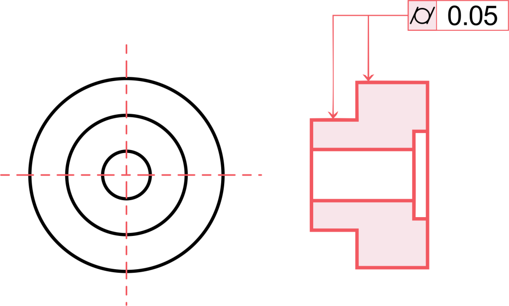
2. Feature Control Frame:
All cylindricity data is in this rectangular box. In drawings, the cylindricity symbol is shown in the first box, followed by the tolerance quantity in the second box.
Unlike certain other GD&T controls, cylindricity has no reference points, so the feature control frame remains simple. Normally, this frame is connected to a dimension line pointing to the controlled cylindrical feature.
3. Diameter Symbol (Ø):
Although not technically a cylindricity symbol, it is usually displayed when describing cylindricity. The diameter symbol indicates the size dimension of your cylindrical feature.
The cylindricity only controls the shape, not the size, so keep that in mind! The cylindricity guarantees that the shape stays within the tolerance; your diameter dimension and the tolerance determine the size limits. Together, they ensure that your cylinder meets both size and shape requirements.
4. Tolerance Block Reference:
The tolerance block on drawings often contains a basic reference: “CYLINDRITY” followed by a standard tolerance value. This applies to all cylindrical features unless a specific feature control frame replaces them.
If you have multiple similar cylindrical features requiring the same shape control, this simplified method prevents your drawing from cluttering multiple feature control frames.
Cylindricity Tolerance Zone
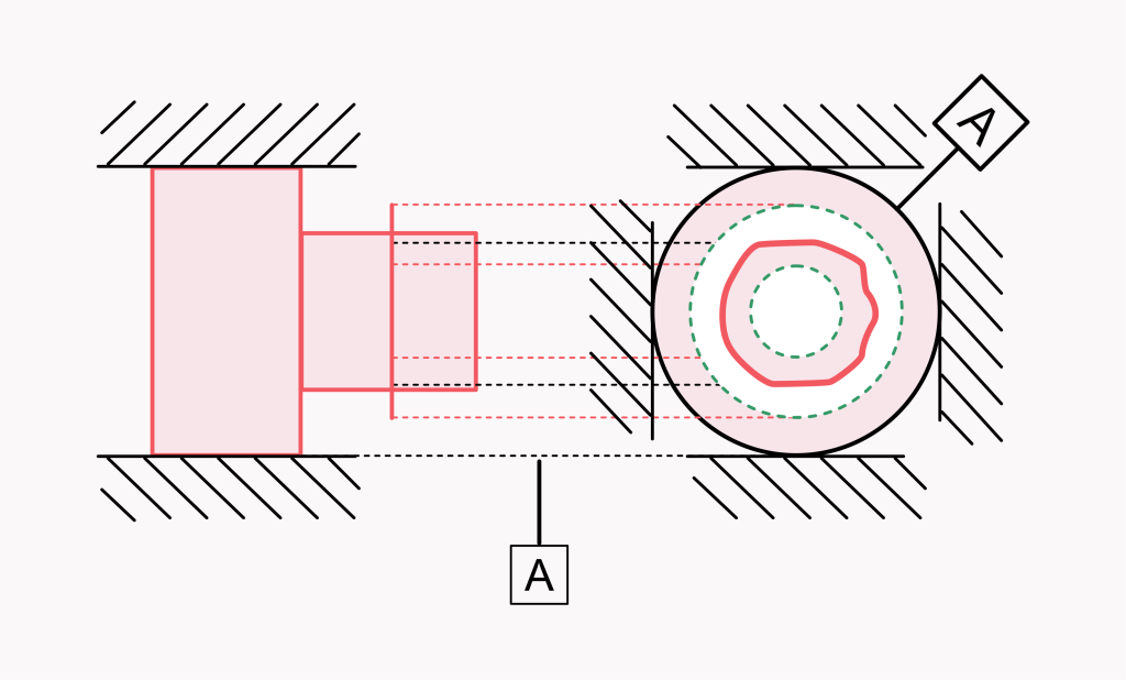
The tolerance zone for cylindricity is where things get exciting. Specifying the cylindricity creates a gap between two concentric cylinders into which your real part surface must fit. Think of it as a 3D sandwich in which your cylinder must remain.
The tolerance zone is a specific thickness that corresponds to your tolerance level. For example, if you specify a cylindricity of 0.05 mm, your tolerance zone is the area between two ideal coaxial cylinders that are exactly 0.05 mm apart. Every unevenness, every indentation on your entire cylindrical surface must fit between these two fictitious cylinders.
Unlike total runout or other geometric controls, cylindricity does not require reference points. It is a shape control that examines your cylindrical feature all by itself. Cylindricity is therefore one of the simpler GD&T controls.
The strength of cylindricity lies in the simultaneous control of the entire surface profile. All these form errors — unevenness, waves, tapering — must remain within your tolerance range. Although the real part can float as long as it stays within the range, the perfect cylinder sits right in the middle between your two concentric cylinders.
Note that your dimensional tolerance does not affect the cylindricity tolerance zone. You need both to fully control your cylindrical component.
How to Measure Cylindricity
Measuring cylindricity is a little more difficult than measuring base diameter, but it’s not too difficult; let me explain! First, you need to measure at various points along the entire length of your cylinder.
The easiest method is to use prisms and a dial gauge. By slowly rotating the cylinder on the prisms, the dial indicator readings are recorded at various points along the axial section. Although this is not very accurate for tight tolerances, it gives a rough idea of the cylindricity.
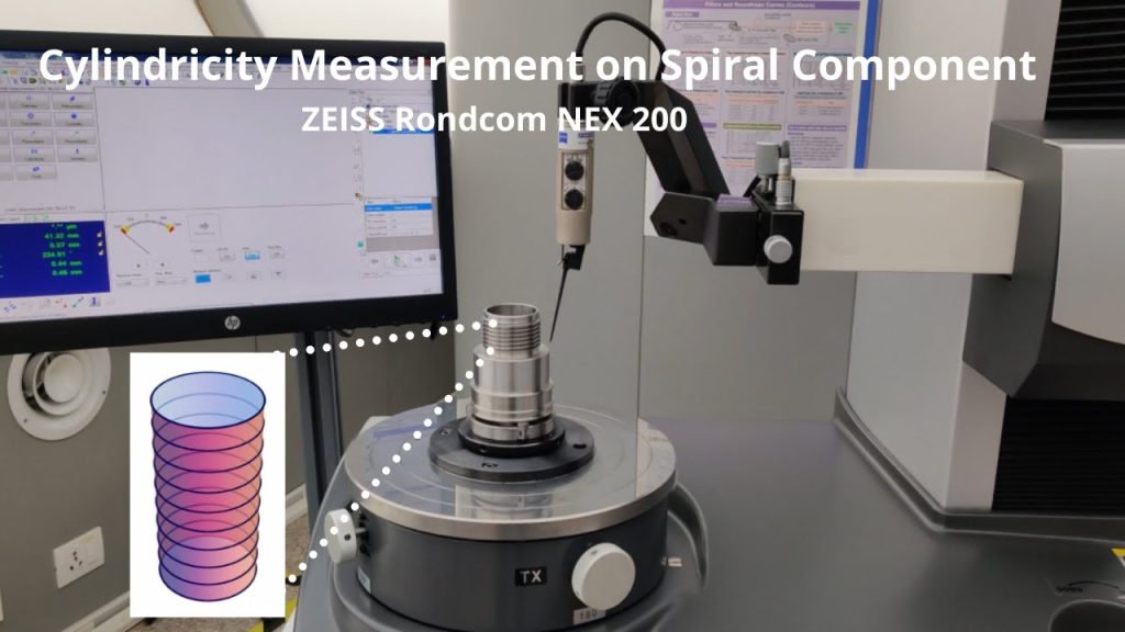
Specialised equipment, such as roundness testers, is used in many stores for more accurate measurements. While a probe checks the surface, these devices rotate the component around its centre axis. The computer algorithm then creates a polar diagram showing the total deviation from a real cylinder by processing these measurements.
Some advanced coordinate measuring machines (CMMs) can also measure cylindricity. They combine multiple cross-section measurements to measure the entire cylindrical surface at once. The machine calculates the total cylindricity error by comparing your actual part to an ideal cylinder.
Not just one! Remember to examine your cylindrical component in several cross-sections. Cylindricity examines the entire surface, so you need data from multiple locations to properly capture your entire shape. Whichever approach you choose, measure the entire cylindrical feature, not just a cross-section.
Applications of Cylindricity
1. Hydraulic and pneumatic cylinders
These parts must be cylindrical! Cylindricity ensures that the entire cylinder surface remains within tolerances when designing components that need to create a perfect seal. Tiny shape errors can lead to leaks or excessive wear in hydraulic cylinders. Remember, if your cylinder is not exactly cylindrical, the pressure can force the fluid through the gaps and cause system failure. Manufacturers, therefore, generally demand strict cylinder tolerances for these applications.
2. Precision shafts and bearings
Good control of cylindricity prevents vibration and premature wear when working with components that rotate at high speeds. Imagine a shaft with a bulge or slight taper that would generate uneven forces as it rotates!
Cylindricity ensures that the entire length retains the correct shape for engineering and automotive applications where shafts must last thousands of hours. This is particularly important when the shaft needs to maintain exact roundness over its entire length.
3. Piston and cylinder bores
The performance of engines and compressors is highly dependent on the relationship between pistons and bores. Poor cylindricity in both parts leads to blow-by, high oil consumption and lower efficiency.
Controlling the cylindricity of these components guarantees uniform clearance over the entire surface. A perfectly cylindrical bore mating with a perfectly cylindrical piston allows for smooth movement but provides an optimal sealing surface.
4. Valve components
Cylindricity ensures the correct seating and sealing of valves that require precise flow control. If a valve stem is not exactly cylindrical, it may leak in some places or jam in others.
Applying cylindricity tolerances to valve parts helps you avoid these problems. This is especially important in high-pressure applications where even small leaks can lead to major problems over time.
5. Precision hole alignments
Cylindricity guarantees correct alignment over the entire depth when multiple holes need to be precisely aligned. Imagine driving a pin through many plates; non-cylindrical holes could cause the pin to jam or seize.
Good control of cylindricity ensures that the entire hole retains its shape, not just the entrance. This is even more important in areas such as aerospace, where precise alignment affects safety and performance.
6. Threaded parts
The cylindricity of the core diameter improves thread engagement and prevents jamming in high-precision threaded parts. Controlling the cylindricity of a threaded shaft ensures consistent thread depth and function.
This is important for precision instruments and critical fastening applications, where proper thread engagement affects both assembly and performance. Improved cylindricity results in stronger, more reliable threaded connections.
What is the Difference Between Cylindricity and Circularity?
The main difference is that cylindricity evaluates the entire cylinder, while circularity only examines a cross-section.
Think of circularity as ensuring that a disc is perfectly round by cutting through your component. If roundness is only checked on one cross-section, the rest of the cylinder could be tapered or wavy.
Cylindricity goes one step further and guarantees that the entire cylindrical surface remains within the tolerance range. It’s like looking at all conceivable cross sections at once to see the circularity! While circularity refers to a single circular cross-section, cylindricity refers to the entire 3D cylindrical feature.
Cylindricity is crucial for all potential roundness defects and other shape defects, such as tapering or curvature. If a part has a slight taper or bend along its length, it may pass a roundness check in multiple places but not meet cylindricity.
In your drawings, you will see different symbols for both shapes; roundness uses a single circle, while cylindricity shows two overlapping half-circles. Although both are important shape controls, cylindricity allows you to better control your cylindrical properties.
Frequently Asked Questions on Cylindricity
Q: What is circularity in GD&T?
A: Circularity measures how close a single cross-section is to perfect roundness. Measuring circularity means that only one section of your part is looked at to ensure that all points on that circle are within tolerance. It’s like seeing if your component forms a perfect circle at a particular point.
Q: What is the difference between concentricity and Cylindricity in GD&T?
A: While concentricity checks whether two features have the same centerline, cylindricity checks whether the shape of your part corresponds to a perfect cylinder. Cylindricity is all about shape; it does not require reference points. Concentricity uses datums to check the relationship between the central axes of features rather than their shapes.
Q: What is the difference between Cylindricity and surface profile?
A: Cylindricity specifically controls cylindrical surfaces in an ideal cylindrical shape. The surface profile is more adaptable, and any surface shape can be controlled to match an ideal surface profile. While cylindricity only applies to cylinders, the surface profile can be used for complicated curves, flat surfaces or any mixture of surface components.
Conclusion
Now you’ve got a solid understanding of cylindricity!
From knowing how to interpret the cylindricity symbol in a feature control frame to understanding how the tolerance zone works between two concentric cylinders, you’re well equipped to use this powerful GD&T control.
Remember, cylindricity looks at your entire cylindrical surface, not just one cross-section like circularity.
Whether you’re designing hydraulic cylinders, precision shafts, or any cylindrical part where form matters, applying proper cylindricity controls will help you build better products.