Face Milling:Process, Tools & Advantage

Face Milling

Share:

Table of Content

Table of Content

Face milling is the most common milling operation in machining. It is used to produce the flat, smooth surfaces on engine blocks, mold bases, and aerospace brackets. In this guide, I will explain how it works, the tools I use, and the practical techniques that improve results.

What Is Face Milling?

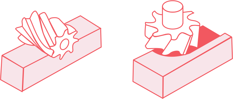
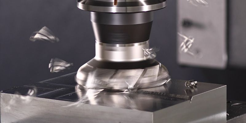
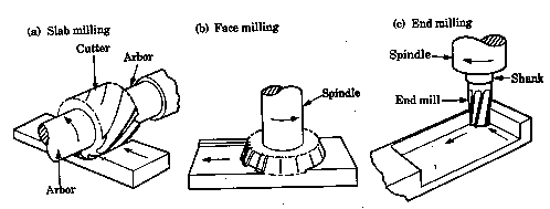
Face milling is a machining process where a rotating cutter — with its axis perpendicular to the workpiece — removes material from the top face of a part to create a smooth, flat surface. The cutting happens on the face of the tool, not the sides.

It’s also called facing, and typically establishes the Z0 datum — the reference surface every other feature on the part is measured from. Cutter diameters usually range from 80 mm to 250 mm.

Face Milling

What Face Milling Is Used For

Face milling is used to produce flat, smooth surfaces on the top of a workpiece. It is typically the first operation in a CNC job, creating the reference surface from which all other features are measured.

These are the main characteristics that define face milling:

  • High material removal rate— large-diameter cutters with multiple inserts clear material in one or two passes.
  • High surface quality— capable of producing finishes down to Ra 0.4 µm, often eliminating the need for grinding.
  • Reference surface creation— establishes the Z0 datum for hole depths, pocket depths, and shoulder heights.
  • Wide material compatibility— works on steel, aluminum, cast iron, titanium, nickel alloys, and plastics.
  • Flat surfaces only— limited to producing planes perpendicular to the spindle axis; curved or 3D features require other operations.

How dose Face Milling Work

Face milling involves a defined sequence of steps. Here is the procedure I follow on every job.

Step 01

Clamp the Workpiece Securely

Load the part into a vise with parallels underneath and tap it down with a dead-blow hammer to seat it flat. Any movement during the cut will produce an uneven surface and put the part out of tolerance.

Step 02

Load the Right Face Mill

Install the face mill into the spindle and check tool runout. Excessive runout — especially above 8,000 RPM — reduces tool life and degrades surface finish.

Step 03

Calculate Spindle Speed and Feed Rate

Calculate spindle speed using n = (1000 × Vc) ÷ (π × D), and feed rate using Vf = fz × z × n, based on the material and cutter. Face mills handle chip loads of 0.08–0.75 mm per tooth, much larger than end mills.

Step 04

Position the Cutter Off-Center

Offset the cutter by 10–20% of its diameter from the workpiece center. This produces a thinner exit chip, smoother cutting forces, and a cleaner surface finish.

Step 05

Start the Cut

Engage the cutter and feed it across the workpiece in a continuous pass. Most face milling jobs finish in one or two passes; avoid frequent entries and exits, as each interruption stresses the cutting edges.

Step 06

Inspect and Repeat if Needed

Check the surface for full coverage and measure the part thickness. If a second pass is required, adjust the depth of cut and run the operation again.

Common Face Milling Tools

Face Milling machines

Selecting the correct cutter has a major impact on the result. These are the four I use most often:

Shell Mills

A shell mill has a cylindrical body with multiple replaceable inserts arranged around its face. It is my standard choice for general-purpose face milling and roughing on larger workpieces.

Indexable Face Mills

These use carbide inserts that can be rotated or replaced when they wear. They are suited for heavy-duty production work where tool life and cost are priorities.

Fly Cutters

A fly cutter uses only one insert. It is slower than multi-insert cutters but produces a high-quality surface finish. I use it for fine finishing on smaller parts, especially aluminum.

End Mills (Used for Face Milling)

When the face I need to mill is inside a pocket where a regular face mill will not fit, an end mill is used instead. It is less efficient, but it is sometimes the only option.

Common Face Milling Operations

types of face milling

Face milling covers several different operations, each with its own cutting parameters and goals. These are the variations I work with most often:

  • General face milling— balanced speed and finish for everyday work.
  • Heavy-duty face milling— big depths of cut, maximum material removal.
  • High-feed face milling— small axial depth (under 2.8 mm) with extreme feed rates, exploiting the chip-thinning effect.
  • Fine finishing— light cuts, sharp inserts, mirror finishes.
  • Step milling— creating multiple levels on a part.
  • Shoulder milling— only with a 90° face mill.

How to Choose the Right Face Milling Cutter

Selecting the correct cutter depends on the workpiece, the operation, and the machine. These are the main factors I consider:

1. Workpiece Material

Match the insert grade and coating to the material. Use uncoated carbide or PCD for aluminum, coated carbide for steel and cast iron, and CBN or ceramic inserts for hardened steel or heat-resistant alloys.

2. Cutter Diameter

Select a cutter diameter 20–50% larger than the width of cut. This ensures the cutter clears the workpiece in one pass and supports off-center positioning for better chip formation.

3. Entering Angle

Choose the entering angle based on the operation: 45° for general-purpose work, 90° for square shoulders and thin-walled parts, round inserts for heavy roughing, and small angles (10°–20°) for high-feed machining.

4. Pitch (Number of Teeth)

Use a coarse pitch for roughing and unstable setups, a medium pitch for general use, and a fine pitch for finishing or stable workpieces with continuous engagement.

5. Depth of Cut and Feed Rate

Match the cutter to the planned depth of cut (ap) and feed per tooth (fz). High-feed cutters require shallow ap with high fz; heavy-duty cutters allow large ap at moderate fz.

6. Machine Capability

Confirm that the spindle has enough power, torque, and rigidity to drive the chosen cutter. Larger diameters and more inserts require higher spindle power and a stable machine.

The Advantages of Face Milling

These are the main reasons I use face milling as the default operation for flat surfaces:

+Advantages

  • High material removal rate

    large diameter combined with multiple teeth removes material quickly.
  • Excellent surface finish

    often down to Ra 0.4 µm.
  • Long tool life

    indexable inserts can be rotated or replaced at low cost.
  • Works on almost any material

    steel, aluminum, cast iron, titanium, nickel alloys, plastics.
  • Creates accurate Z0 datums

    critical for everything that follows.
  • Available on every CNC machining center

    no specialized equipment required.

The Disadvantages of Face Milling

Face milling also has limitations that need to be considered when planning a job:

Disadvantages

  • Only flat surfaces

    curved or 3D features need a different approach.
  • Limited depth of cut

    face mills are not built for deep features.
  • Most can't cut square shoulders

    requires a 90° cutter.
  • High initial tool cost

    quality cutters and inserts are not cheap.
  • Requires rigid machines

    weak machines chatter under large forces.
  • Interrupted cuts damage inserts

    milling over holes or slots causes shock loading.

Face Milling Best Practices

These are the techniques that consistently improve results, extend tool life, and reduce scrap:

1. Position the Cutter Off-Center

This is one of the most important practices. Do not center the cutter on the workpiece. Offsetting it by 10–20% of the diameter produces a thinner exit chip, cleaner finish, and smoother cutting forces. It also reduces vibration.

2. Follow the Golden Rule

The golden rule of milling: always keep at least one tooth engaged with the workpiece at all times. Select your cutter pitch (coarse, medium, fine) so that the cut remains continuous. A momentary gap in engagement is what causes chatter.

3. Use Climb Milling When Possible

Climb milling (down milling) produces thicker entry chips and thinner exit chips, which results in better surface finish and longer tool life. Most modern CNC machines handle climb milling well, provided that backlash is minimal.

4. Reduce Feed Over Interruptions

When the cutter passes over a hole or slot, reduce the feed rate by 50%. Interrupted cuts produce shock loading on the inserts, and a lower feed rate reduces the impact on the cutting edges.

5. Use Coarse-Pitch Cutters for Heavy Work

Fewer teeth provide more chip clearance and generate less heat, which makes coarse-pitch cutters suitable for roughing. Use fine-pitch cutters for finishing passes.

6. Avoid Tiny Axial Depths

If the depth of cut (ap) is smaller than the insert radius, axial forces increase and finish quality decreases. Either use a depth of cut larger than the insert radius, or switch to a high-feed cutter designed for shallow passes.

7. Keep the Tool Engaged

Plan toolpaths that keep the cutter in continuous contact with the workpiece. Frequent entries and exits create stress, dwell marks, and chatter. When the cutter changes direction, use a small radial arc rather than a sharp corner.

8. Use Coolant on High-Speed Cuts

High-pressure coolant clears chips, prevents recutting, and keeps inserts cool. For modern carbide tools running at high speeds, coolant is required to maintain tool life and surface quality.

Written By

Coco is a mechanical engineer and content editor at Aria. She partners with process engineers and shop-floor teams across CNC machining, injection molding, sheet metal fabrication, and surface finishing — turning real production know-how into practical, honest guides for the people designing, specifying, and buying parts.

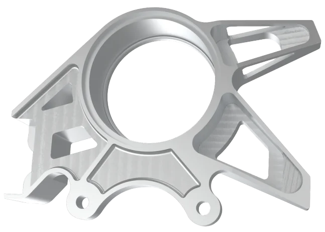
CNC milled aluminum precision part with complex geometry and multiple machining features

Custom Quality Parts By Aria

Send your specs. We’ll get back with a quote in 12 hours.

Scroll to Top