Types of Holes in Engineering: Callout, Machining Methods & Design Tips
Written By: Gavin Leo
Update By:
Gavin Leo
Published:
Updated:
Share:
Table of Content
Table of Content
I have been working in Aria for many years. I’ve seen assemblies fail because someone spec’d a clearance hole where a tapped hole was needed. I’ve watched machinists scratch their heads over a callout that made no sense.
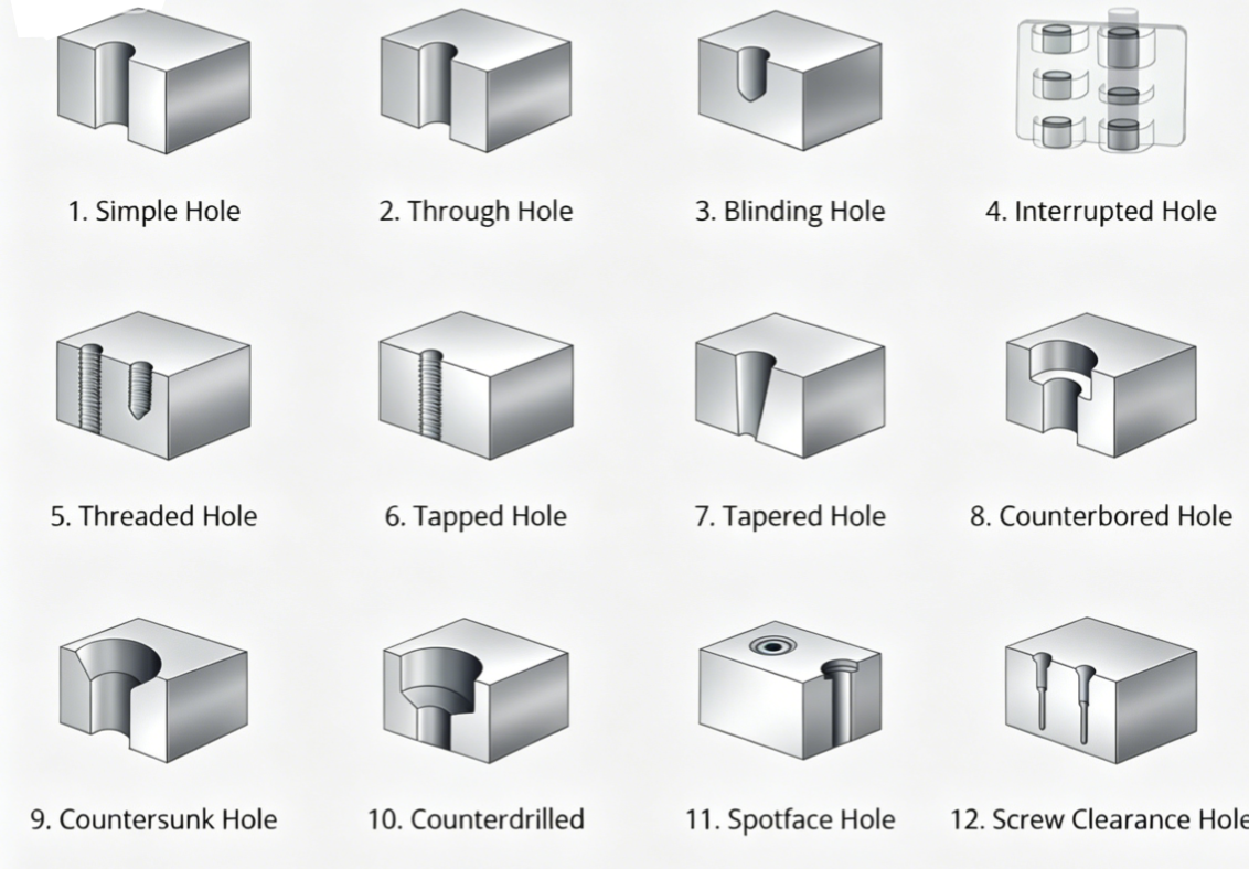
There are 14 common types of engineering holes, including Simple holes, Through Hole, Blind Hole, Interrupted Hole, Threaded Holes, Tapping holes, Counterbore Holes, Spotface Holes,Screw Clearnce Holes etc.
This guide covers common types of engineering holes you’ll encounter in mechanical design, how to read and write their callouts, what they look like in 2D drawings and 3D views, and the machining methods and design tips that actually matter in practice.
What is a Hole in Engineering?
At its most basic, a hole is a void or opening created in a material, typically by a machining or drilling operation. But in engineering, “hole” means a lot more than that.
A hole is a designed feature with specific geometric requirements: diameter, depth, location, tolerance, and often additional characteristics like threads, countersinks, or spot faces. Each of these requirements gets communicated through a standardized callout on the engineering drawing.
Get the callout right and the machinist knows exactly what to make. Get it wrong and you’re looking at scrap, rework, or a part that doesn’t assemble.
An Overview of 14 Types of Engineering Holes
Hole type
Cross-section
Primary purpose
Simple hole
A plain cylindrical void of specified diameter. The base feature that all other hole types build on.
Through Hole
Penetrates the full material thickness. Used for fasteners, rods, fluid passages, and pin locations.
Blind Hole
Terminates at a specified depth inside the part. Used for fastener seats, pin locators, and ports that must not break through the wall.
Interrupted Hole
A drill path that crosses an internal cavity or cross-bore. Requires reduced feed rate to prevent tool deflection and breakage.
Screw Clearance Hole
Oversized to let the fastener shank pass through freely without threading. Clamping force comes from the head and nut bearing on the part faces.
Tapped Hole
Drilled then threaded with a tap so a bolt engages directly with the part material. Eliminates the need for a separate nut.
Threaded Hole
Through-threaded bore produced by tapping or thread-milling. Accepts a bolt or stud from either side with a specified thread class and fit.
Counterbore Hole
Flat-bottomed cylindrical recess recesses a socket-head bolt flush or below the part surface. Provides a clean face with no protruding fastener head.
Countersink Hole
Conical entry seats a flat-head screw flush with the part surface. Angle must match the fastener series: 82° for inch series, 90° for metric.
Counterdrill Hole
Larger-angle conical recess produced by a larger drill (not a countersink cutter). Used for specialised fastener heads or conical-seat fluid fittings.
Spotface Hole
Minimal-depth flat recess that creates a clean bearing surface on a rough cast or inclined face. Depth is just enough to clean up the material.
Tapered Hole
Conical bore with a defined taper ratio. Self-centres and self-locks tapered shanks, pins, and pipe threads (Morse taper, NPT, BSPT).
Reamed Hole
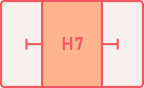
Drill-then-ream sequence achieves H7 or tighter tolerance with a superior surface finish. Required for dowel pins, bearings, and close-fit shaft locations.
Overlapping Hole
Two or more bores whose cylindrical volumes intersect. Creates complex internal geometry used in valve bodies, manifold blocks, and fluid passages.
There are two broad families of holes in mechanical engineering: Basic Hole Types (simple geometric forms) and Machined and Fastener Holes (holes designed to interface with specific hardware or require specialized machining). I’ll walk through both.
Basic Hole Types
1. Simple Hole
A simple hole is exactly what it sounds like: a cylindrical void of a specified diameter. No threading, no counterbore, no special geometry. Just a round hole with a defined size and location.
Simple holes show up everywhere, from pin locations and dowel holes to ventilation features and fluid passages. They’re the foundation everything else builds on.
The Callout Symbol Of Sample Hole
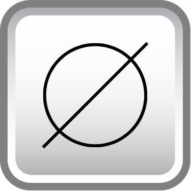
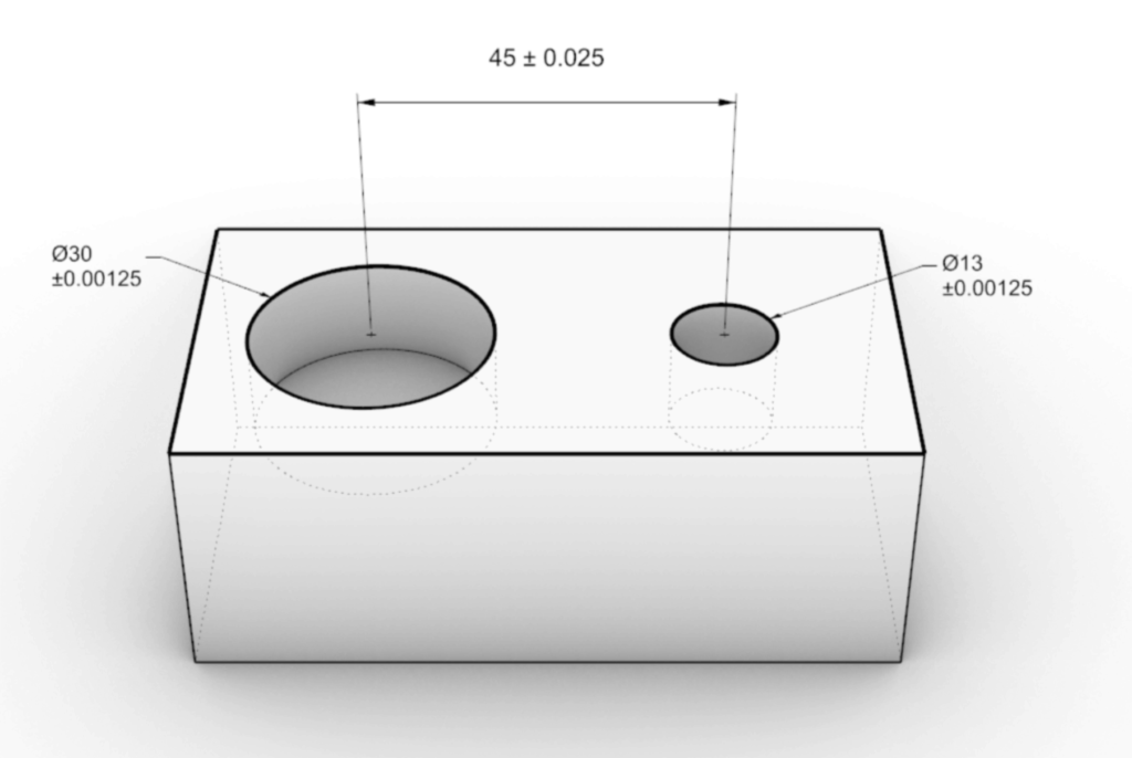
A simple hole callout typically shows the diameter symbol (Ø) followed by the diameter value.
Example:
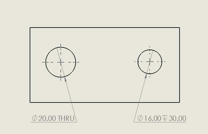
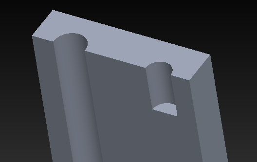
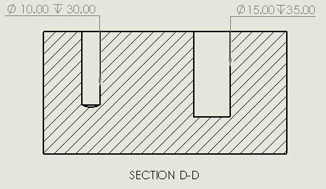
In this drawing a 20 mm diameter hole that passes through the object is represented by Ø 20.00 Through.
Another hole 16.00 mm diameter whose depth is less than the thickness of the block is represented by Ø 16.00 “depth symbol” ↓ 30.00.
Sample Hole 2D Drawing
Sample Hole 3D Drawing
2. Through Hole
A through hole passes completely through the material from one face to the other. It’s one of the most common hole types in any mechanical assembly, used for fasteners, pins, rods, shafts, and fluid passages.
The key distinction from a simple hole description is that “through” tells the machinist (and the reader) that no depth dimension is needed because the drill exits on the far side.
The Callout Symbol Of Through Hole
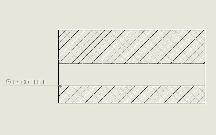
Through holes have a hole callout with the diameter symbol ‘Ø’ and the words ‘THRU’.
In modern practice following ASME Y14.5-2018, if no depth is specified and the context is clear, the hole is understood to be through.
Example: Ø15.0 THRU or simply Ø15.0 with the view making it clear the hole is through.
Through Hole 2D Drawing
Through Hole 3D Drawing
3. Blind Hole
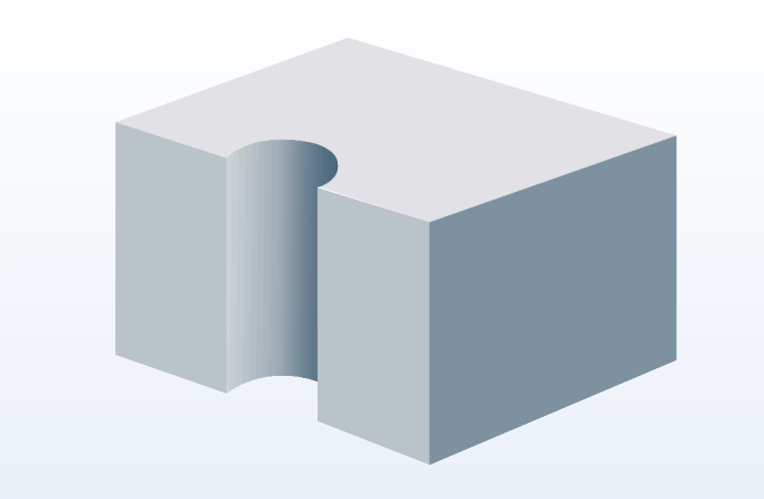
A blind hole has a specified depth but does not break through the opposite face of the material. It terminates inside the part. Blind holes are used when you need a fastener seat, a pin location, or a fluid port without breaking through the part wall.
The Callout Symbol of Blind Hole
The callout symbol is its diameter ‘Ø’ and a depth symbol ‘↓’. These symbols have the corresponding measurements specified in the callout.
Example: Ø10.0 ↓ 30.0 (10mm diameter, 30mm deep)
Blind Hole 2D Drawing
Blind Hole 3D Drawing
4. Interrupted Hole
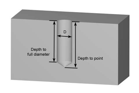
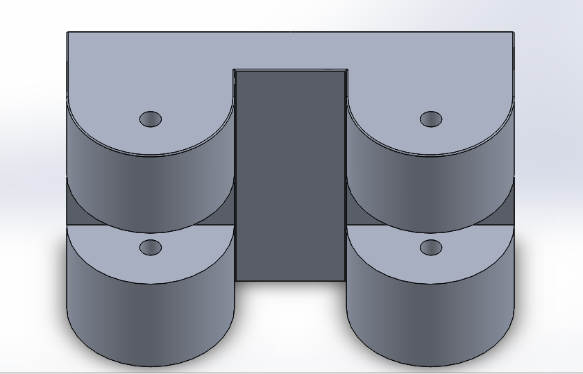
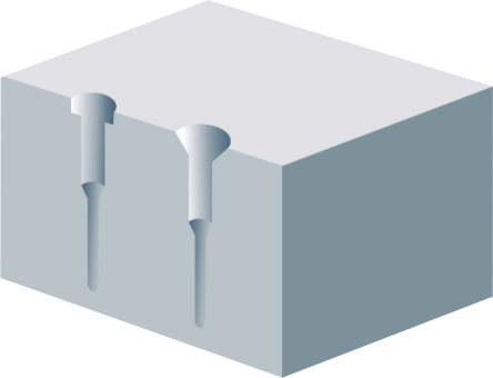
An interrupted hole is one where the drill passes through one or more internal voids or cross-holes during machining. In other words, the hole intersects a cavity, a slot, or another hole partway through its depth.
This one’s important from a machining standpoint. When a drill bit enters an interrupted cut, it loses support on one side. The bit can deflect, wander, or in worst cases, break. It’s a situation that requires slower feeds, sharp tooling, and sometimes a pilot hole or different tool path strategy.
The Callout Symbol of Interrupted Hole
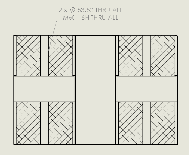
There is no unique GD&T symbol for interrupted holes. The callout follows the standard format for the hole type (through or blind), but the drawing cross-section will reveal the interrupted geometry.
Example: Ø58.5 THRU (INTERRUPTED CUT) or a note in the title block: Contains interrupted bore, reduce feed rate.
Interrupted Hole 2D Drawing
Interrupted Hole 3D Drawing
Machined & Fastener Holes
5. Screw Clearance Hole
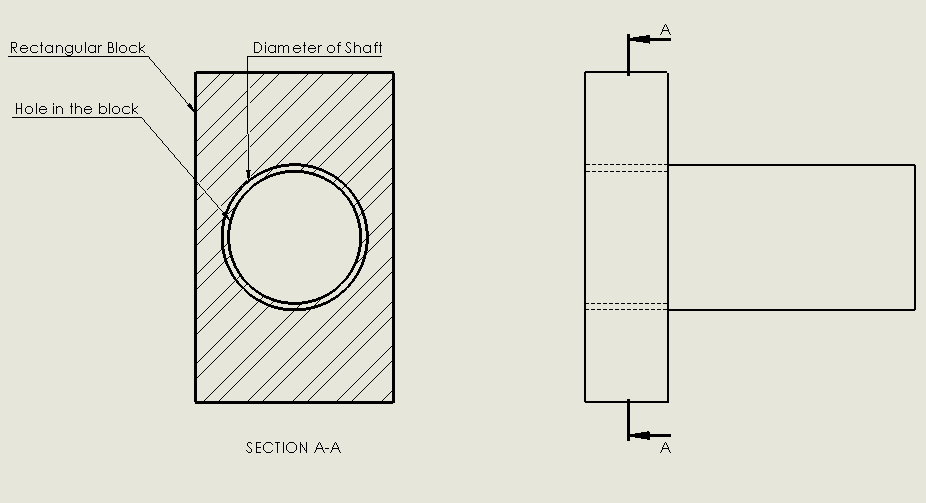
A clearance hole is sized larger than the fastener shank that passes through it. The fastener doesn’t thread into this hole. Instead, it passes through freely and threads into the mating part (or a nut on the other side). The clamping force comes from the fastener head and nut bearing against the two parts.
Clearance holes come in three classes: close fit, normal fit, and loose fit. The class you choose depends on how much positional variation you can tolerate in the assembly.
Clearance holes are specified by diameter, often referenced to a fastener size. For an M8 bolt on a normal fit:
Example:Ø8.4 THRU (for M8 normal clearance)
ASME B18.2.8 and ISO 273 provide standard clearance hole sizes by fastener diameter and fit class.
Screw Clearance Hole 2D Drawing
Screw Clearance Hole 3D Drawing
6. Tapped Hole
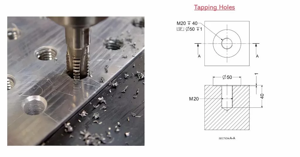
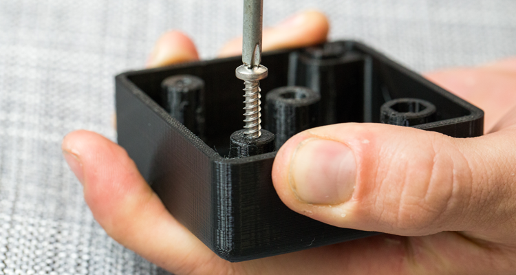
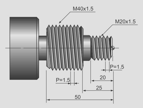
A tapped hole is a blind or through hole that has been drilled and then threaded with a tap, a cutting tool that creates helical threads on the interior cylindrical surface.The threads allow a bolt or screw to engage directly with the part material, without a separate nut.Tapped holes are everywhere in mechanical assemblies.Any time a screw goes directly into a part (a machine housing, a bracket, a fixture plate), it’s going into a tapped hole.
Example :M20 x 1.25 THRU or M8 x 1.25 ↓ 40.0
7. Threaded Hole
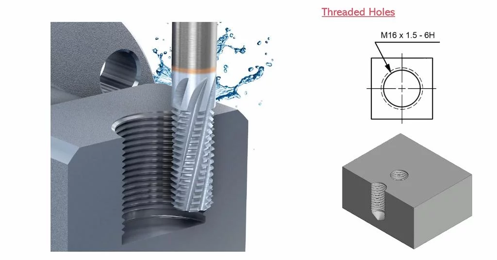
The terms “tapped hole” and “threaded hole” are often used interchangeably, and in many contexts they mean the same thing: a hole with internal threads. However, “threaded hole” can also refer to holes produced by thread milling (rather than tapping), or to internal threads produced by other means such as thread forming or rolling.
In precision machining applications, thread milling is often preferred over tapping for larger diameter holes, harder materials, or when thread quality and positional accuracy are critical. A thread mill produces the same thread form as a tap but removes material in a helical path rather than all at once.
When thread quality (class of fit) is critical, it’s added to the callout: Example: M16 x 1.5 – 6H THRU (6H is a standard tolerance class for internal metric threads)
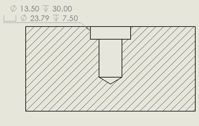
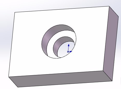
8. Counterbore Hole
A counterbore is a cylindrical enlargement at the entrance of a hole. It has a flat bottom and straight walls, and it’s sized to accept the head of a fastener (typically a socket head cap screw or a hex bolt) so that the head sits flush with or below the part surface.
The counterbore has three key dimensions: the through hole diameter (for the fastener shank), the counterbore diameter (to clear the fastener head), and the counterbore depth (to sink the head to the desired level).
The Callout Symbol Of Counterbore Hole
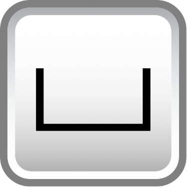
The counterbore symbol is a stylized upside-down “T” (⌴). The callout lists the through hole first, then the counterbore:
Example:Ø13.5 ↓ 30.0 ⌴ Ø23.79.0 ↓ 7.5
This reads as: 13.5mm through hole, 6.5mm deep, counterbored to 23.79mm diameter, 7.5mm deep.
Counterbore Hole 2D Drawing
Counterbore Hole 3D Drawing
9. Countersink Hole
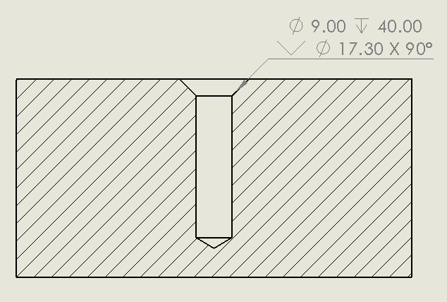
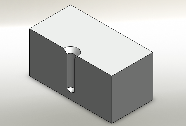
A countersink is a conical enlargement at the entrance of a hole. Unlike a counterbore’s flat bottom, the countersink has an angled seat that matches the underside of a flat-head screw. When the screw is tightened, the conical head seats into the conical recess and the top of the screw sits flush with the part surface.
The countersink angle matters. The most common angle for standard flat-head screws is 82 degrees (inch series, ASME) or 90 degrees (metric, ISO). These are not interchangeable. Using a 90-degree countersink with an 82-degree screw leaves the head above flush. Using an 82-degree countersink with a 90-degree screw creates a line contact instead of full bearing, which can gall the part surface under load.
The Callout Symbol Of Countersink Hole
The countersink symbol looks like a downward-pointing “V” with a horizontal line through it (⌵). The callout includes the through hole diameter, the countersink diameter (at the surface), and the angle:
Example: Ø9.00 ↓ 40.00 ⌵ Ø17.30 x 90°
This reads as: 9.0mm through hole, 40mm deep, countersunk to 17.30mm at the surface, at a 90-degree included angle.
Countersink Hole 2D Drawing
Countersink Hole 3D Drawing
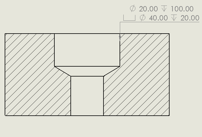
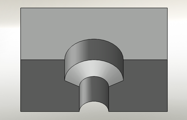
10. Counterdrill Hole
A counterdrill (also called a counterdrilled hole) is similar in concept to a counterbore but produced with a larger twist drill rather than a flat-bottomed boring tool. The result is a conical bottom at the stepped region rather than a flat one. It’s essentially a countersink produced at a larger diameter before the through hole continues at a smaller diameter.
Counterdrill holes are used when a specific conical seat geometry is needed, often for specialized fasteners with conical heads that are different from standard flat-head screw profiles, or for fluid fittings that require a conical seat for sealing.
The Callout Symbol Of Counterdrill Hole
There is no universal standardized symbol for counterdrill holes. They are typically called out with a note specifying both diameters and the included angle:
Example:Ø20.0 THRU with a note Ø40.00 X 90° ↓ 20 COUNTERDRILL
Counterdrill Hole 2D Drawing
Counterdrill Hole 3D Drawing
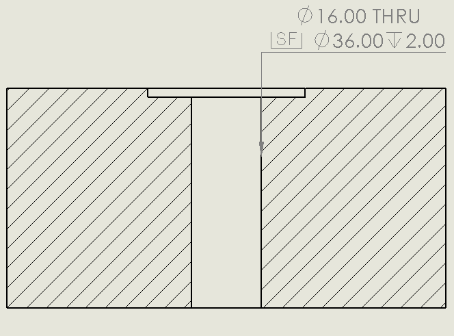
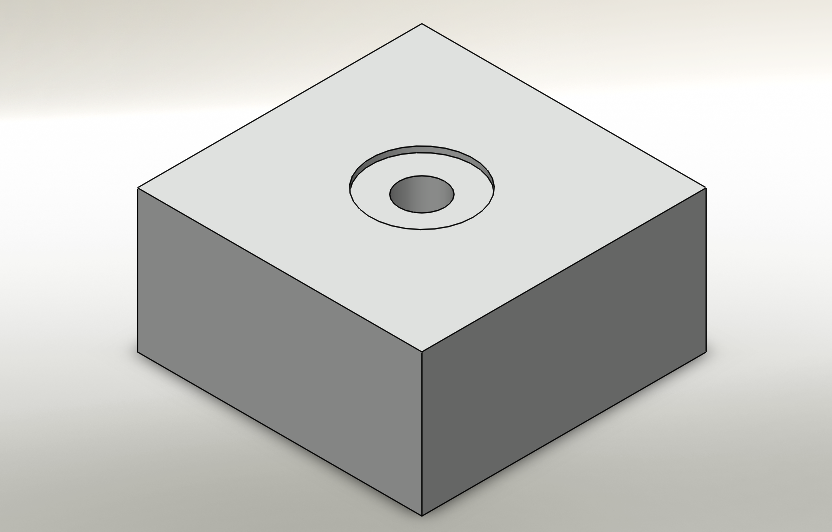
11. Spotface Hole
A spotface is a shallow, flat-bottomed recess machined around a hole, just deep enough to create a clean, flat bearing surface for a fastener head or washer. It’s used when the base surface of the part is rough (as-cast, as-forged, or inclined) and you need a reliable flat datum for the fastener.
The depth of a spotface is minimal, typically just enough to clean up the surface (often 0.5 to 2mm). If no depth is specified on the drawing, the machinist typically machines just enough to produce a full, clean flat. The diameter is sized to clear the fastener head or washer being used.
The Callout Symbol Of Spotface Hole
The spotface symbol is the same as counterbore (⌴) with the letters “SF” added, or it may appear as “SFACE” in a note. When no depth is specified:
Example:Ø36.0 ⌴ SF (spotface to 11mm diameter, depth as required)
Or with a depth: Ø36.0 ⌴ SF ↓ 2.0
Spotface Hole 2D Drawing
Spotface Hole 3D Drawing
12. Tapered Hole
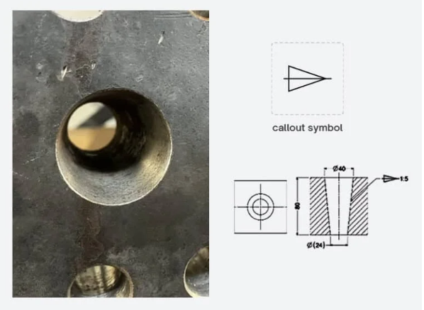
A tapered hole has a diameter that changes continuously along its depth, creating a conical bore. The most common applications are Morse taper holes (for tooling shanks and arbors), pipe thread connections (NPT and BSPT), and precision tapered pin holes in positioning fixtures.
Tapered holes are excellent for self-centering and self-locking applications. A tapered pin driven into a tapered hole wedges itself in place and can be removed and reinstalled repeatedly with consistent positioning. This is why tapered pins are standard practice for locating fixture components.
Taper is typically expressed as a ratio (1:20, 1:50) or as an angle per side. Morse tapers have their own standardized series with specific taper ratios.
The Callout Symbol Of Tapered Hole
Tapered holes are called out with the major diameter, minor diameter, length, and taper ratio or angle:
Example:Ø40.0 / Ø24.0 X 50.0 LONG (TAPER 1:5)
13. Reamed Hole
A reamed hole is a drilled hole that has been finish-machined with a reamer to achieve a tighter diameter tolerance and better surface finish than drilling alone can provide. The reaming operation removes a very small amount of material (typically 0.1 to 0.3mm) from the drilled bore.
Reamed holes are used where close fits are required: dowel pin holes, bearing bores, shaft locations, and precision hinge pins. Standard drilled holes hold tolerances of roughly H12-H11. Reamed holes can achieve H7 and tighter, which is the tolerance class required for interference and transition fits with pins and shafts.
14. Overlapping Hole
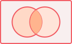
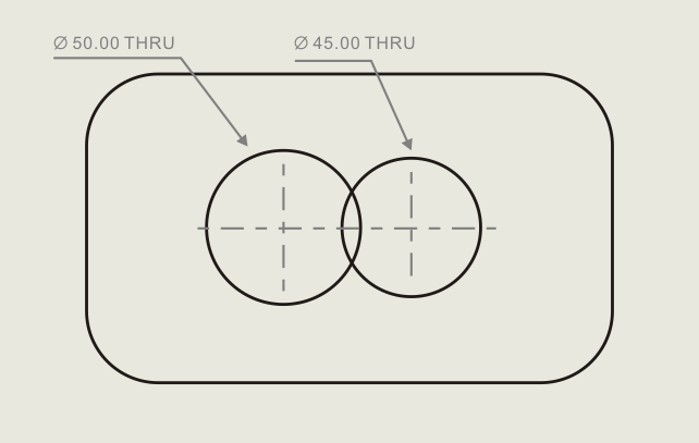
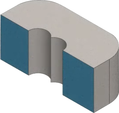
An overlapping hole (sometimes called an intersecting hole) is created when two or more holes are positioned so that their cylindrical volumes intersect. The result is a non-cylindrical void with complex internal geometry.
Overlapping holes occur in some valve bodies, manifold blocks, and hydraulic components where fluid passages must intersect at specific angles. They also appear in some die and mold designs.
Example:Ø50.0 THRU / Ø45.0 THRU
Overlapping Hole 2D Drawing
Overlapping Hole 3D Drawing
Common Methods for Hole Machining
Every hole type I’ve described above gets made by some combination of machining operations. Here’s a practical rundown of what’s actually happening in the shop.
Drilling
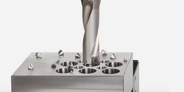
Drilling is the starting point for almost every hole. A twist drill removes material by rotating and advancing axially into the workpiece. Drilling is fast and economical but produces relatively loose tolerances (IT12-IT11 typically) and a surface finish that limits its precision applications.
Reaming
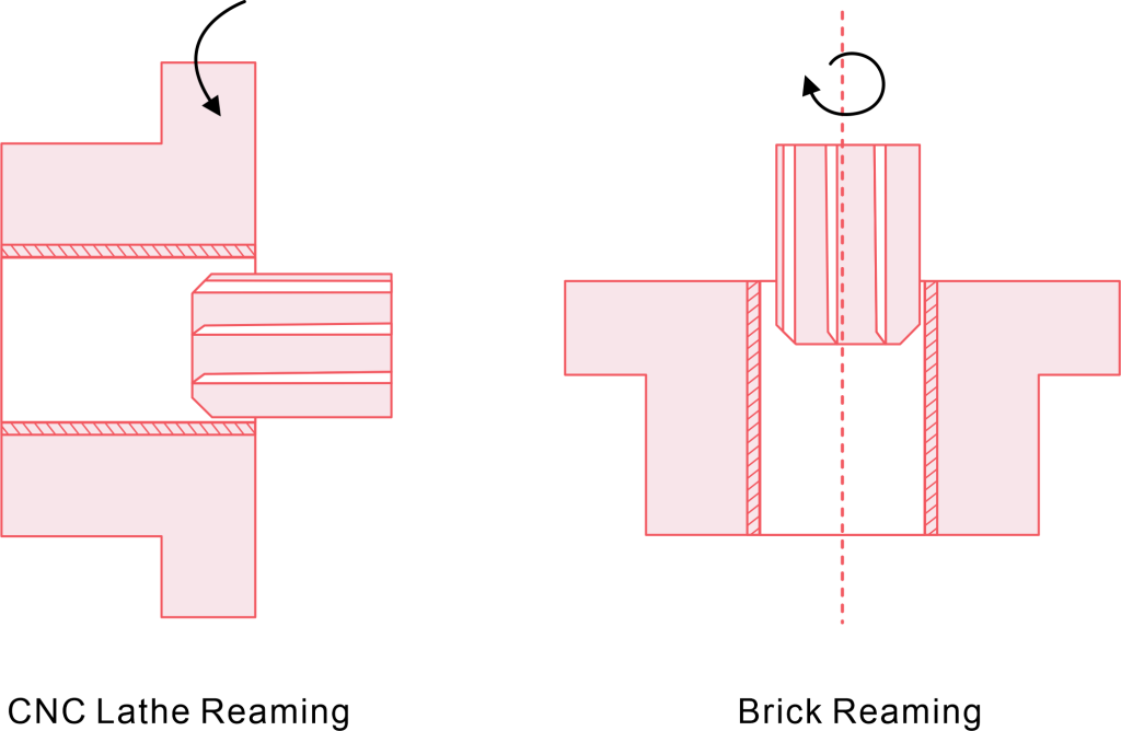
Reaming follows drilling when tighter tolerances are needed. The reamer is a multi-fluted precision tool that removes a small amount of stock and leaves a very accurate, smooth bore. For dowel holes and bearing fits, reaming is standard.
Boring
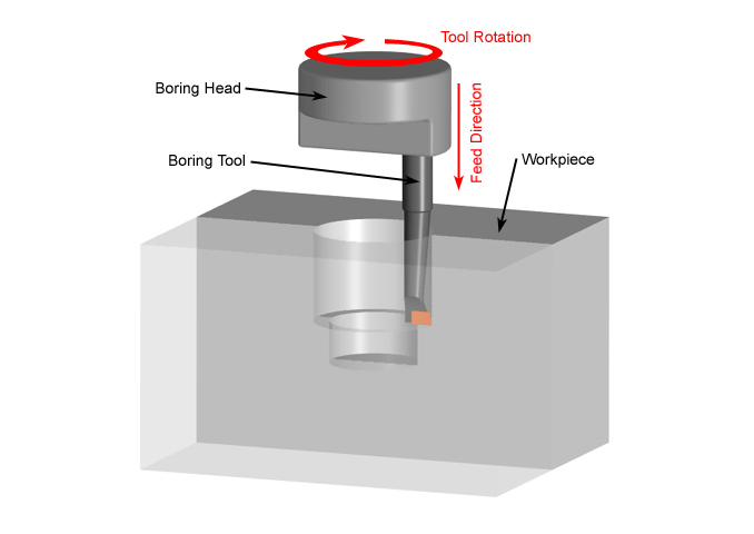
Boring uses a single-point cutting tool rotated on a boring bar to enlarge and true up a drilled hole. Boring can achieve excellent roundness and straightness and is commonly used for larger diameter precision bores that exceed the practical range of reamers.
Tapping
Tapping cuts internal threads using a tap: a hardened, fluted cutting tool with the thread form ground into it. Tapping can be done by hand or by CNC with a synchronized spindle. Thread forming (cold forming rather than cutting) is an alternative that produces stronger threads in softer materials by displacing rather than removing material.
Thread milling
Thread milling uses a rotating thread mill tool to generate the thread form in a helical path. It’s slower than tapping but more flexible: one tool can cut multiple thread sizes, and it can be used in materials that are difficult or impossible to tap conventionally.
Counterboring
Counterboring uses a flat-bottomed end mill or a dedicated counterbore tool. The through hole is drilled first, and then the counterbore tool pilots in the existing hole to produce the larger stepped recess.
Countersinking
Countersinking uses a countersink cutter (a conical cutter with the appropriate included angle) to create the angled entry. The through hole is drilled first, then the countersink is run in to the required diameter at the surface.
Design Tips for Engineering Holes
After years of designing parts and watching them come back from the shop, I’ve collected a few rules I stick to.
Size your holes to standard tooling
Drill bits come in standard sizes. If you design a 7.3mm hole when a 7.5mm hole would also work, you’ve just created a special tooling requirement. Use standard drill series sizes wherever the function allows it.
Think about depth-to-diameter ratio on blind holes
Drilling a hole much deeper than 3-5 times the diameter without peck drilling cycles is asking for chip packing and drill breakage. For very deep holes (greater than 10x diameter), you’re into gun drilling territory, and that changes your manufacturing approach completely.
Never design to minimum wall
I’ve seen drawings that calculate the absolute minimum wall between two holes and then call it out exactly. Leave margin. A 0.5mm minimum wall on paper becomes a scrapped part when drilling tolerances stack up.
For tapped holes, specify both thread depth and drill depth
The drill depth needs to be deeper than the thread depth to allow tap runout. As a rule of thumb, add 5 threads worth of depth (5 x pitch) to the required thread depth to get the minimum drill depth. Some standards have specific recommendations for this.
Consider access for tooling
A tapped hole in a pocket with 8mm clearance around it looks fine in CAD. In the shop, the tap holder needs to fit in that pocket too. Build enough clearance for the tooling that will make the feature.
Custom Quality Parts By Aria
Send your specs. We’ll get back with a quote in 12 hours.
Gavin Leo is a content editor at Aria Manufacturing with hands-on experience in CNC machining, Injection molding, materials selection, and part design. Outside of work, he enjoys hiking and collecting mechanical watches.


 EU
EU